STANDARD RECOMMENDED PROCEDURE 003-722 | ISSUE 4 | OCTOBER 2015 | PAGE 9 OF 10
Step 2: Slide drawer back to original position.
Step 3: If previously removed, slide the cover back in the retaining anges on top of the
housing. Push the plunger fasteners to secure.
Step 4: Close the front and rear doors.
4.8 Install Jumpers
Step 1: Remove dust caps from the
connectors and adapters into
which they will be mated. Refer to
Section 5 for cleaning instructions.
Clean connector end-faces and
adapters per standard company
practices and insert connectors
into adapters.
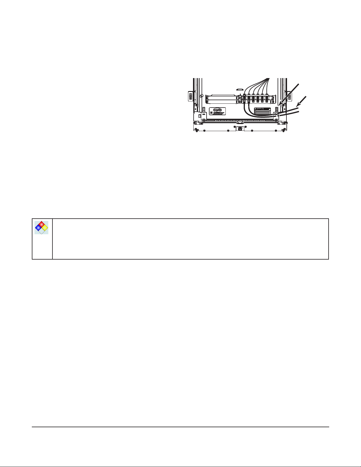
Figure 12
Step 2: Install jumpers as specied on planning diagrams. Route jumpers through the routing
clips on either side at the front of the housing (Figure 12).
Step 3: Provide enough jumper slack to allow the connector panel tray to slide to the back
and forward positions without violating the minimum bend radius of the jumper.
Step 4: Record jumper routing information on the provided identication label. Accurate
recordkeeping is imperative for an organized installation.
5. Connector Care and Cleaning
WARNING: Isopropyl alcohol is ammable with a ashpoint at 54ºF. It can cause irritation to
eyes on contact. In case of contact, ush eyes with water for at least 15 minutes. Inhalation
of vapors irritates the respiratory tract. Exposure to high concentrations has a narcotic effect,
producing symptoms of dizziness, drowsiness, headache, staggering, unconsciousness and
possibly death.
• Always keep dust caps on connectors and adapters when not in use.
• Ensure dust caps are clean before reuse.
• Use optical cleaning materials as standardized by your company.
• Clean the connector before every mating, especially for test equipment patch cords
(jumpers).
• A minimum level of cleaning is listed below. Local procedures may require more rigorous
cleaning methods.
Step 1: Remove plugs from the connector adapter.
Step 2: Wipe the connector ferrule twice with a lint-free wiping material moistened with
isopropyl alcohol. Then wipe across the end of the ferrule.
Step 3: Repeat previous step with a dry wipe.
6. Testing
6.1 Provisioning Tests
Equipment should be tested from the source (or central ofce) to receiver at the time of
provisioning to verify signal continuity and acceptable loss limits. Use an optical power meter to
verify signal continuity and determine loss measurements are within specied local standards.
KPA-0156
Clips
Jumpers