manuals.online logo
Brands
  1. Home
  2. •
  3. Brands
  4. •
  5. CORNING
  6. •
  7. Cables And Connectors
  8. •
  9. CORNING UniCam SRP-006-150 User manual

CORNING UniCam SRP-006-150 User manual

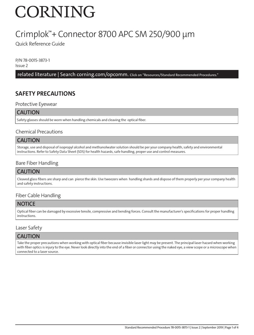
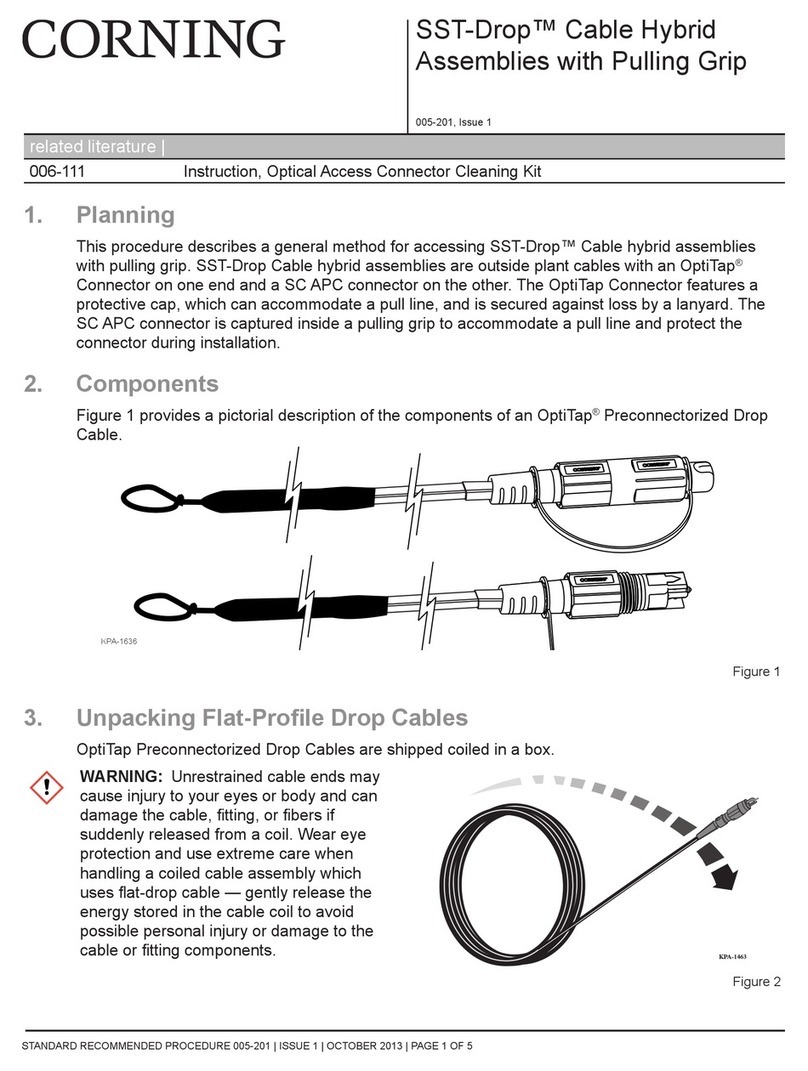
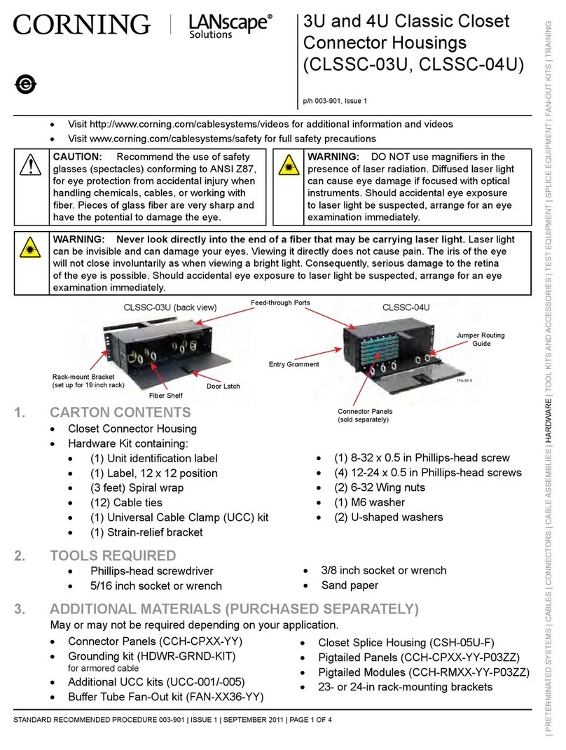
This procedure is intended to guide you through the critical steps to ensure successful installation of a Unicam connector. Refer to
SRP-006-150 for complete instructions and precautions and visit www.corning.com/cablesystems/unicamvideo for more information.
Corning Cable Systems
SRP-006-083
Issue 7 December 2006
Page 1 of 2
Critical Ste s for 1 and 2-fiber UniCam® Connectors
The wrench handle on the
installation tool must be in
the up position.
1
SRP-006-083
Date
code
Cam
key
Cam
key
Latch
Cam
key Central
groove
"U " label on
dust cap "U " label on
dust cap
SC LC
MT-RJ
ST-
compatible
U
P
Cam
key
Connector cams may move slightly in shipment, so verify that the connector is in its
open position:
• FC and ST connectors are in their open position when the key is 90° from the "up" on
the dust cap.
• MT-RJ connectors are in their open position when the key is 90° from the "up" on the
dust cap.
• SC connectors are in their open position when the key is 90° from the date code.
• LC connectors are in their open position when the key is 90° from the latch which secures
the front dust cap.
2
FC
LC SC
MT-RJ
FC and
ST-compatible
Non-CTS installations: lace the connector into the tool correctly:
• FC and ST with the "up" on the dust cap must be up.
• LC connectors with the latch up.
• SC connectors with the "date code" up.
• MT-RJ with the "up" on the dust cap must be up.
3
Single-fiber connectors
LC
Slide the strain relief boot onto the fiber/cable. For
LC connectors slide the boot on, then slide the
trigger on.
4
5
Visual mark:
9 mm for LC
11 mm for SC, ST, FC and MT-RJ
9 mm for LC
11 mm for SC, ST, FC and MT-RJ
Fan-out Tubing Applications Jacketed Cable Applications
900 µm coated fiber 900 µm coated fiber 900 µm coated fiber
Visual mark:
250 µm coated fiber
4 mm
900 µm Buffer Applications
Bare fiber
40 mm
Bare fiber
40 mm 40 mm
Bare fiber
11 mm
Cable 2 mm
Visual mark for LC
Aramid yarn (13 mm)
Mark, strip and clean the fiber. Some fibers have a clear coating over the glass that is difficult to see.
• For 900 µm Buffer Applications, strip and clean to the 40 mm mark.
• For 900 µm Fan Out Applications, strip and clean to the 40 mm mark and strip only the 900 µm tubing to the 44 mm mark.
Ensure all coatings are removed and that the fiber is clean. Wipe the fiber clean with 90%+ isopropyl alcohol. Any coating left on
the bare fiber will not fit into the connector splice and will have adverse effects on performance. Do not remove the visual mark.
CTS Installations: Remove the clear ferrule dust cap on all
connectors. For LC and ST-compatible connectors, also
remove the black load adapter.
LC
ST-compatible
Corning Cable Systems reserves the right to improve, enhance, and modify the features and specifications of
Corning Cable Systems’ products without prior notification.
All trademarks are the property of their respective holders.
Corning Cable Systems is ISO 9001 certified.
© 2006 Corning Cable Systems LLC
All rights reserved.
Corning Cable Systems LLC
O Box 489
Hickory, NC 28603-0489 USA
For US and Canada 1-800-743-2673
International 828-901-5000
FAX: 828-901-5973
http:www.corning.com/cablesystems
Page 2 SRP-006-083 Issue 7
15
10
Cleave the fiber. The FBC-012 cleaver
is recommended.However, any cleaver
capable of producing quality cleaves
between 8mm and 10mm of bare fiber
can be used.
For the FBC-012 cleaver: load the fiber
into the handler. lace the handler into
the FBC-012 so that the edge of the fiber
coating contacts the edge of the left-hand
cleaver pad. Do this visually; do not slide the handler over against the stop. While holding the
handler in this position slowly press the cleaver’s handle as far as it will go. Gently release the
handle and remove the fiber handler. Open the handler and remove the fiber.
For the FBC-001 cleaver: position the marks so that
the buffer coating lines up with the fiber guide’s stop
and the end of the fiber is secured under the spring-
loaded fiber clamp. ress down the cleaver arm until it
touches the fiber guide. This will "score" the fiber. Only
light pressure is necessary. Release the cleaver arm, then
gently flex the fiber guide to break the fiber. If the fiber
guide is flexed excessively to break the
fiber, a poor cleave will result.
Once the fiber is cleaved, do not clean the fiber, or allow it to contact anything. If the cleave does contact something, start again.
6
14 11
14 11
11 14
11 14
Blade
Bare fiber
end
Stop
FBC-012
FBC-001
900 µm Tight-buffered
250 µm Fan-out
Coated fiber edge
Bare fiber
Visual mark
Release button
25.4 mm (1 in.)
minimum
900 µm
ress the roller release button and load
the buffered fiber between the rollers.
7
ress the release button and lift straight
up to remove fiber.
2
1
21297-08UC
Key
U
P
ST-
compatible FC LC
SC
MT-RJ
Date
beveled
edges
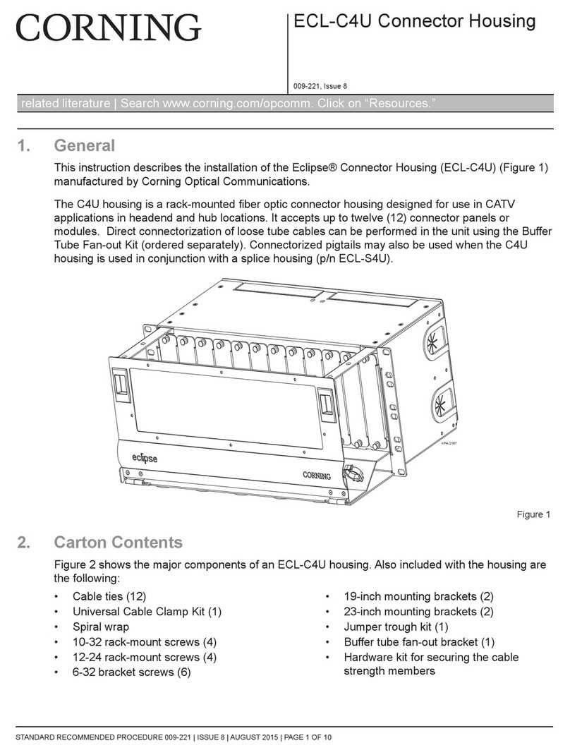
Depending on the connector type, add the appropriate hardware, additional strain relief,
and connector boots.
• FC, ST, and MT-RJ slide boot onto connector.
• SC connectors slide boot onto connector then insert connector into housing with the
housing "key" and connector "date code" aligned.
• LC connectors install the trigger before sliding boot onto connector.
4
1
P
U
Insert the fiber into the lead in tube.
The visual mark on the fiber must
be within 2 mm of the lead in tube.
8
2 mm
Visual mark
Front of tool
Use the rollers to apply inward pressure on the
fiber so a slight bow forms for 1.6, 2.0, or 2.9 mm
applications; form a 12 mm (0.5 in.) bow
for 900 µm applications.
9
Rotate the crimp handle 180° until it
contacts the lead in tube. ush the
handle down firmly and lift it back up.
1
1
Crimp handle
Move the slider handle back and
lift out the connector.
3
1
>90°
Rotate the wrench handle down 90°
to cam the connector.
0
1
This manual suits for next models

1

Other CORNING Cables And Connectors manuals

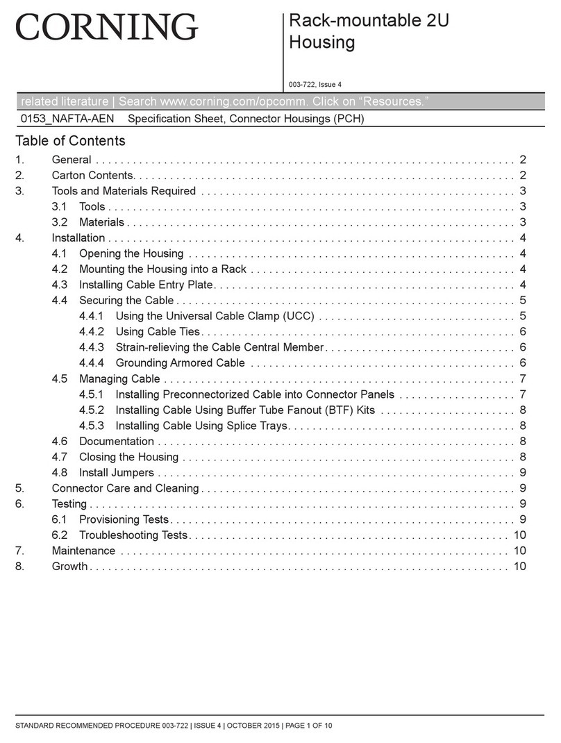
CORNING ClearCurve SRP-005-065 User manual

CORNING

CORNING ClearCurve SRP-005-065 User manual

CORNING Gold 000301T4180002M User manual

CORNING

CORNING Gold 000301T4180002M User manual

CORNING Lanscape Solutions CLSSC-03U User manual

CORNING

CORNING Lanscape Solutions CLSSC-03U User manual

CORNING SRP-004-067 User manual

CORNING

CORNING SRP-004-067 User manual

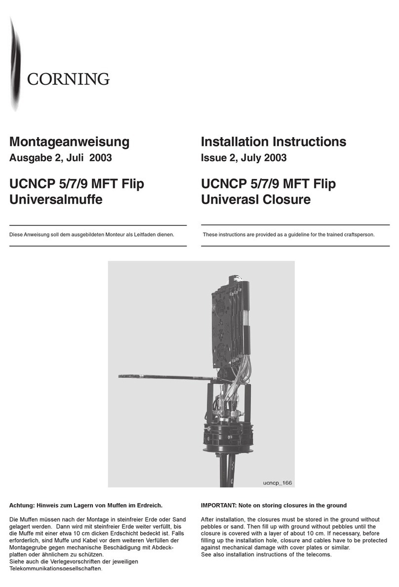
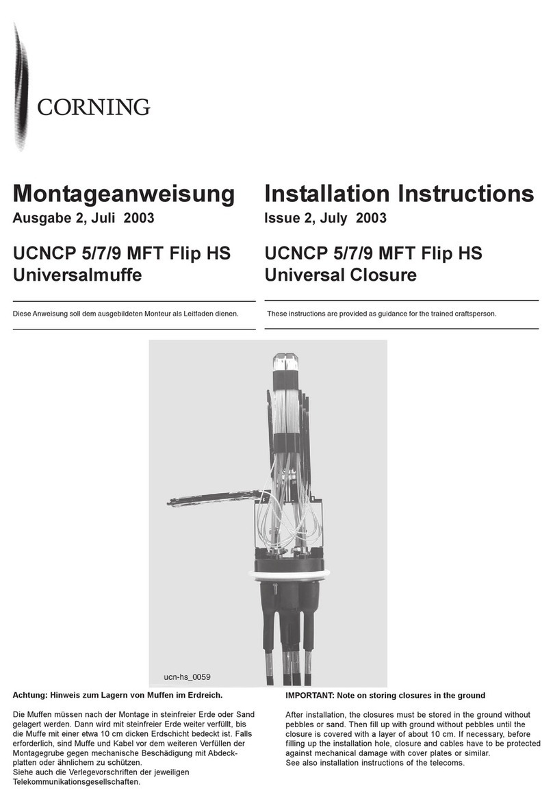
CORNING UCNCP 5 MFT Flip HS Series User manual

CORNING

CORNING UCNCP 5 MFT Flip HS Series User manual

CORNING ECL-C4U User manual

CORNING

CORNING ECL-C4U User manual

CORNING Crimplok+ Connector 8700 APC SM 250/900 mm User manual

CORNING

CORNING Crimplok+ Connector 8700 APC SM 250/900 mm User manual

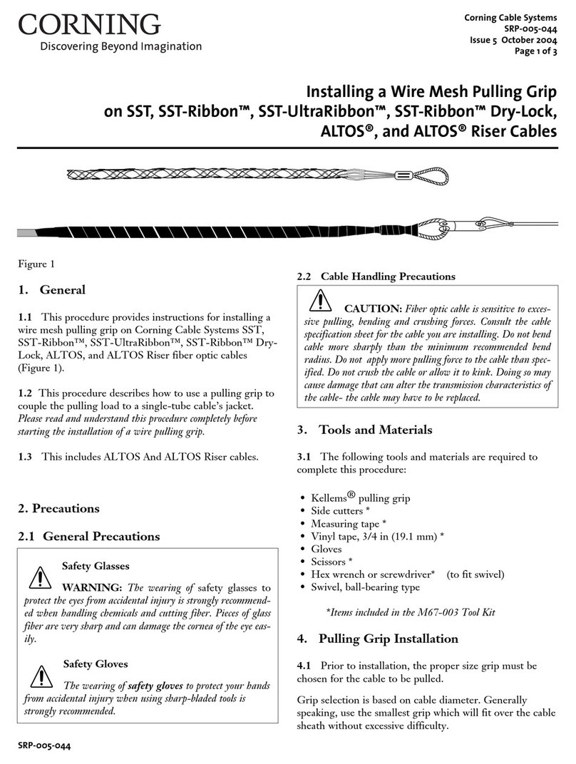
CORNING SST Instruction Manual

CORNING

CORNING SST Instruction Manual

CORNING SST-Drop User manual

CORNING

CORNING SST-Drop User manual

CORNING PCH-02U User manual

CORNING

CORNING PCH-02U User manual

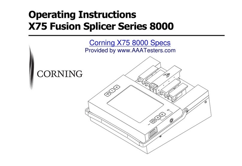
CORNING X75 8000 Series User manual

CORNING

CORNING X75 8000 Series User manual

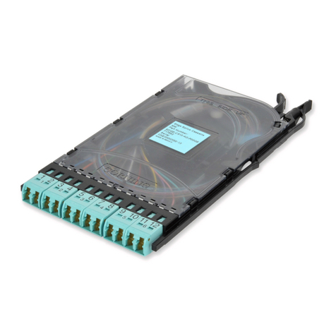
CORNING EDGE Splice Cassette User manual

CORNING

CORNING EDGE Splice Cassette User manual

CORNING EDGE-01U-SP User manual

CORNING

CORNING EDGE-01U-SP User manual

CORNING UCNCP 5 MFT Flip HS Series User manual

CORNING

CORNING UCNCP 5 MFT Flip HS Series User manual

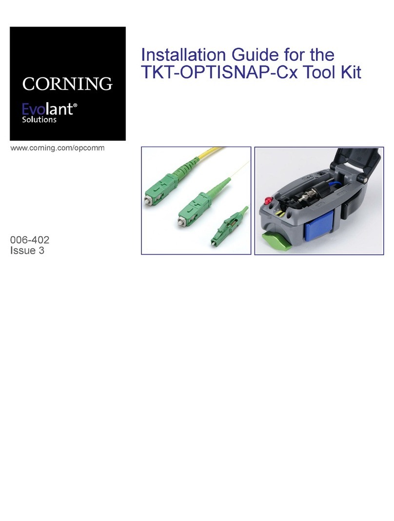
CORNING Evolant TKT-OPTISNAP-Cx User manual

CORNING

CORNING Evolant TKT-OPTISNAP-Cx User manual

Popular Cables And Connectors manuals by other brands

brennenstuhl H05VV-F3G1,5 Instructions for use

brennenstuhl

brennenstuhl H05VV-F3G1,5 Instructions for use

HRS EM30MSD Series quick start guide

HRS

HRS EM30MSD Series quick start guide

Leviton 40735-R Instructions for use

Leviton

Leviton 40735-R Instructions for use

Philips SWA4303W Specifications

Philips

Philips SWA4303W Specifications

3M 5415A-IJ instructions

3M

3M 5415A-IJ instructions

Tibor Everglades quick start guide

Tibor

Tibor Everglades quick start guide

Philips SWV2913W Specifications

Philips

Philips SWV2913W Specifications

Alemite 7340 Service guide

Alemite

Alemite 7340 Service guide

Heimeier Vekotec Installation and operating instructions

Heimeier

Heimeier Vekotec Installation and operating instructions

MSA FP STRYDER 10051455 User instructions

MSA

MSA FP STRYDER 10051455 User instructions

Yaesu SCU-19 installation manual

Yaesu

Yaesu SCU-19 installation manual

SY Electronics SY-HS14E-18G user manual

SY Electronics

SY Electronics SY-HS14E-18G user manual

Rockwell Automation Allen-Bradley Bulletin 1485P KwikLink installation instructions

Rockwell Automation

Rockwell Automation Allen-Bradley Bulletin 1485P KwikLink installation instructions

Indian Motorcycle 2880986 instructions

Indian Motorcycle

Indian Motorcycle 2880986 instructions

Nexans N42i.900 Termination instructions

Nexans

Nexans N42i.900 Termination instructions

AAVARA PS128 installation guide

AAVARA

AAVARA PS128 installation guide

Sumitomo TYPE-Q102-CA+ Guide to Operation

Sumitomo

Sumitomo TYPE-Q102-CA+ Guide to Operation

CircuitWerkes AC-3 Technical manual

CircuitWerkes

CircuitWerkes AC-3 Technical manual

manuals.online logo
manuals.online logoBrands
  • About & Mission
  • Contact us
  • Privacy Policy
  • Terms and Conditions

Copyright 2025 Manuals.Online. All Rights Reserved.