manuals.online logo
Brands
  1. Home
  2. •
  3. Brands
  4. •
  5. CORNING
  6. •
  7. Cables And Connectors
  8. •
  9. CORNING UCNCP 5 MFT Flip HS Series User manual

CORNING UCNCP 5 MFT Flip HS Series User manual

Other manuals for UCNCP 5 MFT Flip HS Series

1

This manual suits for next models

5

Other CORNING Cables And Connectors manuals

CORNING EDGE-01U-SP User manual

CORNING

CORNING EDGE-01U-SP User manual

CORNING Evolant TKT-OPTISNAP-Cx User manual

CORNING

CORNING Evolant TKT-OPTISNAP-Cx User manual

CORNING SST Instruction Manual

CORNING

CORNING SST Instruction Manual

CORNING UCNCP 5 MFT Flip HS Series User manual

CORNING

CORNING UCNCP 5 MFT Flip HS Series User manual

CORNING UniCam SRP-006-150 User manual

CORNING

CORNING UniCam SRP-006-150 User manual

CORNING Crimplok+ Connector 8700 APC SM 250/900 mm User manual

CORNING

CORNING Crimplok+ Connector 8700 APC SM 250/900 mm User manual

CORNING X75 8000 Series User manual

CORNING

CORNING X75 8000 Series User manual

CORNING SST-Drop User manual

CORNING

CORNING SST-Drop User manual

CORNING ECL-C4U User manual

CORNING

CORNING ECL-C4U User manual

CORNING PCH-02U User manual

CORNING

CORNING PCH-02U User manual

CORNING SRP-004-067 User manual

CORNING

CORNING SRP-004-067 User manual

CORNING ClearCurve SRP-005-065 User manual

CORNING

CORNING ClearCurve SRP-005-065 User manual

CORNING Lanscape Solutions CLSSC-03U User manual

CORNING

CORNING Lanscape Solutions CLSSC-03U User manual

CORNING Gold 000301T4180002M User manual

CORNING

CORNING Gold 000301T4180002M User manual

CORNING EDGE Splice Cassette User manual

CORNING

CORNING EDGE Splice Cassette User manual

Popular Cables And Connectors manuals by other brands

StarTech.com ST124HD20 quick start guide

StarTech.com

StarTech.com ST124HD20 quick start guide

Philips SWV4543S/10 Features

Philips

Philips SWV4543S/10 Features

Larson Electronics 10-50C instruction manual

Larson Electronics

Larson Electronics 10-50C instruction manual

Grip MEK-PM Assembly and operating manual

Grip

Grip MEK-PM Assembly and operating manual

Ultra Products Travel Pack #3 ULT31436 Specifications

Ultra Products

Ultra Products Travel Pack #3 ULT31436 Specifications

Surpass QCH-F Operation manual

Surpass

Surpass QCH-F Operation manual

Philips SWA6310 Specifications

Philips

Philips SWA6310 Specifications

StarTech.com CRJ4550PK quick start guide

StarTech.com

StarTech.com CRJ4550PK quick start guide

Nohau EMUL-IP2K-PC user guide

Nohau

Nohau EMUL-IP2K-PC user guide

Foxun SX-SP144E-HD4K2K operating instructions

Foxun

Foxun SX-SP144E-HD4K2K operating instructions

Philips SWA3305W Specifications

Philips

Philips SWA3305W Specifications

opticis Stretch DVIM1-1P0x user manual

opticis

opticis Stretch DVIM1-1P0x user manual

Volkswagen VAS 6558A operating manual

Volkswagen

Volkswagen VAS 6558A operating manual

NEXIBO N-13 user manual

NEXIBO

NEXIBO N-13 user manual

CYP PU-1H3HBTL Operation manual

CYP

CYP PU-1H3HBTL Operation manual

Allen-Bradley 1784-u2dhp installation instructions

Allen-Bradley

Allen-Bradley 1784-u2dhp installation instructions

Global Caché Flex Link Blaster quick start

Global Caché

Global Caché Flex Link Blaster quick start

Hauppauge USB-Live2 Quick installation guide

Hauppauge

Hauppauge USB-Live2 Quick installation guide

manuals.online logo
manuals.online logoBrands
  • About & Mission
  • Contact us
  • Privacy Policy
  • Terms and Conditions

Copyright 2025 Manuals.Online. All Rights Reserved.

UCNCP 5/7/9 MFT Flip 1
Achtung: Hinweis zum Lagern von Muffen im Erdreich.
Die Muffen müssen nach der Montage in steinfreier rde oder Sand
gelagert werden. Dann wird mit steinfreier rde weiter verfüllt, bis
die Muffe mit einer etwa 10 cm dicken rdschicht bedeckt ist. Falls
erforderlich, sind Muffe und Kabel vor dem weiteren Verfüllen der
Montagegrube gegen mechanische Beschädigung mit Abdeck-
platten oder ähnlichem zu schützen.
Siehe auch die Verlegevorschriften der jeweiligen
Telekommunikationsgesellschaften.
IMPORTA T: ote on storing closures in the ground
After installation, the closures must be stored in the ground without
pebbles or sand. Then fill up with ground without pebbles until the
closure is covered with a layer of about 10 cm. If necessary, before
filling up the installation hole, closure and cables have to be protected
against mechanical damage with cover plates or similar.
See also installation instructions of the telecoms.
Installation Instructions
Issue 2, July 2003
UCNCP 5/7/9 MFT Flip
Univerasl Closure
Montageanweisung
Ausgabe 2, Juli 2003
UCNCP 5/7/9 MFT Flip
Universalmuffe
These instructions are provided as a guideline for the trained craftsperson.
Diese Anweisung soll dem ausgebildeten Monteur als Leitfaden dienen.
2UCNCP 5/7/9 MFT Flip
Inhaltsübersicht
1. Inhalt der Muffenpackung
2. Zubehör (gesondert zu bestellen)
3. Technische Daten
4. Vorbereiten der Kabel
5. Montage des Dichtungskörpers
6. Einführen eines Abzweigkabels
7. Vorbereiten der Bündeladern
8. Befestigen der Kassetten am Scharnierblock
9. Beschreibung der Kassette
10. Spleißen
11. Schließen der Muffe
12. Wiederöffnen des Dichtungskörpers
13. Nachträgliche Montage eines Abzweigkabels
1. Inhalt der Muffenpackung
1. Haube
2. Dichtungskörper
3. Spannring
4. Dichtungsring
5. Kassettenhalter
6. Verschlußschrauben für Dichtungskörper
7. Doppelabfangungswinkel Hauptkabel
8. Kabelschellen
9. Zentralelement-Abfangung / -Erdung
10. Erdungsschraube / Erdungsschraube (belüftet)
11. Verschlußschraube
12. Lehre / Schlüssel
13. Reinigungstuch
14. Pinsel
15. Gleitmittel
16. Dichtungspaste
17. Schrauben für Kassettenhalter
18. Dichtungsband
19. Dichtungsband für Dichtungskörper
20. Montageanweisung
Contents
1. Contents of Closure Pack
2. Accessories (to be ordered separately)
3. Technical Data
4. Preparing the Cables
5. Installing the End Cap
6. Inserting a Branching Cable
7. Preparing the Buffer Tubes
8. Mounting the Trays on the Hinge Block
9. Description of Tray
10. Splicing
11. Closing the Closure
12. Re-opening the End Cap
13. Later Installation of a Branching Cable
1. Contents of Closure Pack
1. Canister
2. End cap
3. Clamping ring
4. Sealing ring
5. Tray holder
6. Closing screws for end cap
7. Double strain relief bracket for main cable
8. Cable clamps
9. Strain relief / grounding for central members
10. Grounding screw / Grounding screw (vented)
11. Plug
12. Gauge / wrench
13. Cleaning tissue
14. Brush
15. Lubricant
16. Sealing paste
17. Screws for tray holder
18. Sealing tape
19. Sealing tape for end cap
20. Installation instructions
2
3
4
5
67
8
9
10
11
12 13
14
16 17
18
1
19
15
20
UCNCP 5/7/9 MFT Flip 3
1.1 Zubehör für ein zusätzliches Kabel
(kann auch gesondert bestellt werden)
1. Dichtungen
2. Druckschraube
3. Verschlußschraube
4. Zahnscheibe
5. Kabelschelle
6. Abfangungswinkel 1-fach
7. Zentralelement-Abfangung / -Erdung
2. Zubehör (gesondert zu bestellen)
1. Tragseilaufhängung
2. Prüfventil, Dichtungspaste
3. Blindstopfen
4. Mast- und Wandbefestigung
5. Spiralschlauch und Schlauchstutzen
6. MFT Kassetten und Kabelbinder
1.1 Accessories for One Additional Cable
(can also be ordered separately)
1. Sealings
2. Pressure screw
3. Closing screw
4. Washer
5. Cable clamp
6. Bracket, 1-way strain relief
7. Strain relief / grounding for central members
2. Accessories (to be ordered separately)
1. Messenger strand suspension
2. Test valve, sealing paste
3. Dummy plug
4. Pole and wall mounting
5. Spiral wrap and nozzles
6. MFT splice trays and cable ties
1
4
3
2
5
6
7
2
3
1
4
5 6
4UCNCP 5/7/9 MFT Flip
3. Technische Daten 3. Technical Data
pyT
epyT
mmnießaM
snoisnemiD
mmni
egnälresaFmm0021iebegnälredalednüB.niM
htgnelrebifmm0021tahtgnelreffub.niM
aLaD
enettinhcseg
lebaK
selbactuc
)A(
lebaKenettinhcseg
selbactuc
)B(
enettinhcsegnu
lebaK
selbactucnu
)C(
egnälresaF.nim
htgnelrebif.nim
81-5PCNCU
4pilFTFM 5945810022 nedrewtlettimreregärtnettessaKmaßum
redlohyartehttadenimretedebtsum 00440021
22-7PCNCU
8pilFTFM 5759420032 nedrewtlettimreregärtnettessaKmaßum
redlohyartehttadenimretedebtsum 00640021
81-9PCNCU
61pilFTFM 5946030042 nedrewtlettimreregärtnettessaKmaßum
redlohyartehttadenimretedebtsum 00840021
Tabelle 1 Table 1
La
Da
Skizze 1 / Sketch 1
35 35
Kabelmantel
Cable sheath
Zentralelement
Central member Bündelader
Multifiber buffer tube
A
geschnittenes Kabel cut cableSkizze 2 / Sketch 2
35 35
Kabelmantel
Cable sheath
Schnitt
Incision
Bündelader
Multifiber buffer tube
Zentralelement
Central member
C
ungeschnittenes Kabel uncut cable
Skizze 3 / Sketch 3
UCNCP 5/7/9 MFT Flip 5
Die Dichtungskörper UCN P 5, 7, 9 bieten die Mög-
lichkeit, 5, 6 oder 8 Kabel einzuführen. Die beiden
Öffnungen in der Trennebene sind für (ungeschnit-
tene) Hauptkabel mit einem maximalen Außendurch-
messer von 20, 22 oder 32 mm vorgesehen. In die
Stopfbuchsen können nur geschnittene Kabel mit
einem maximalen Außendurchmesser von 15, 18 oder
25 mm installiert werden. Eine Vielzahl von Kabel-
konfigurationen ist möglich. Die folgende Anweisung
bezieht sich daher nur auf einen typischen An-
wendungsfall.
The UCN P 5,7,9 end caps allow 5, 6 or 8 cables to be
inserted.
The two openings in the seam area are provided for
(uncut) main cables with a maximum outside diameter of
20, 22 or 32 mm. The glands can only be used to install
cut cables with a maximum outside diameter of 15, 18 or
25 mm. A large number of cable configurations is
possible. The following instructions therefore merely
apply to a typical application.
geschnittenes Kabel cut cableSkizze 4 / Sketch 4
45
B
Kabelmantel
Cable sheath
Zentralelement
Central member
Bündelader
Multifiber buffer tube
Faser
Fiber
pyT
epyT
tnemeganaMresaF
tnemeganamrebiF
lhaznAelamixaM
rebmunmumixaM
nettessakßielpS
syartecilpS
eßielpssnoisuF
nresaflezniE
secilpsnoisuF
srebifelgnis
redØdnulhaznA
lebaK
selbacfoØdna.oN
81-5PCNCU
4pilFTFM
pilFTFM
484mm51-5x3
mm02-21x2
22-7PCNCU
8pilFTFM 869mm81-5x4
mm22-21x2
81-9PCNCU
61pilFTFM 61291 mm52-21x6
mm23-21x2
Tabelle 2 Table 2
3.1 Kabeleinführungsbereich 3.1 Cable Entry Area
UCNP 5 UCNP 9UCNP 7
Ventil / Erddurchführung
Valve / ground feedthrough
Mast- / Tragseilbefestigung
Pole / messenger mounting
Skizze 5 / Sketch 5
6UCNCP 5/7/9 MFT Flip
3.2 Für einige Installationsschritte ist
die Lehre zu verwenden. Kabeldurch-
messer nur mit dieser Lehre messen.
UCNCP 4/5 MFT Flip
A = Schlüssel für Verschlußschraube
C = Lehre für Dichtungsbandwickel in
der Trennebene
E = max. Kabeldurchmesser für
kleinsten Dichtungsgummi (10 mm)
F = max. Kabeldurchmesser für
größten Dichtungsgummi (15 mm)
G = Schlüssel für Druckschraube
H = Verschlußlehre
K = min. Kabeldurchmesser für
kleinsten Dichtungsgummi (5 mm)
UCNCP 4/5 MFT Flip
A = Wrench for closing screw
C = Gauge for sealing tape wrap in the
seam
E = Max. cable diameter for smallest
rubber sealing (10 mm)
F = Max. cable diameter for largest
rubber sealing (15 mm)
G = Wrench for pressure screw
H = Closing gauge
K = Min. cable diameter for smallest
rubber sealing (5 mm)
3.2 Some installation steps req ire the
se of the gage. Use only this gage to
meas re cable diameters.
UCNCP 6/7 MFT Flip
A = Schlüssel für Verschlußschraube
B = Schlüssel für Erdungsschraube
C = Lehre für Dichtungsbandwickel in
der Trennebene
D = max. Kabeldurchmesser für
mittleren Dichtungsgummi (14 mm)
E = max. Kabeldurchmesser für
kleinsten Dichtungsgummi (9,5 mm)
F = max. Kabeldurchmesser für
größten Dichtungsgummi (18 mm)
G = Schlüssel für Druckschraube
H = Verschlußlehre
K = min. Kabeldurchmesser für
kleinsten Dichtungsgummi (5 mm)
UCNCP 6/7 MFT Flip
A = Wrench for closing screw
B = Wrench for grounding screw
C = Gauge for sealing tape wrap in the
seam
D = Max. cable diameter for center
rubber sealing (14 mm)
E = Max. cable diameter for smallest
rubber sealing (9.5 mm)
F = Max. cable diameter for largest
rubber sealing (5 mm)
G = Wrench for pressure screw
H = Closing gauge
K = Min. cable diameter for smallest
rubber sealing (5 mm)
UCNCP 8/9 MFT Flip
A = Schlüssel für Verschlußschraube
B = Schlüssel für Erdungsschraube
C = Lehre für Dichtungsbandwickel in
der Trennebene
D = max. Kabeldurchmesser für
mittleren Dichtungsgummi (21 mm)
E = max. Kabeldurchmesser für
kleinsten Dichtungsgummi (16,5 mm)
F = max. Kabeldurchmesser für größten
Dichtungsgummi (25 mm)
G = Schlüssel für Druckschraube
H = Verschlußlehre
K = min. Kabeldurchmesser für
kleinsten Dichtungsgummi (12 mm)
UCNCP 8/9 MFT Flip
A = Wrench for closing screw
B = Wrench for grounding screw
C = Gauge for sealing tape wrap in the
seam
D = Max. cable diameter for center
rubber sealing (21 mm)
E = Max. cable diameter for smallest
rubber sealing (16.5 mm)
F = Max. cable diameter for largest
rubber sealing (25 mm)
G = Wrench for pressure screw
H = Closing gauge
K = Min. cable diameter for smallest
rubber sealing (12 mm)
Skizze 6 / Sketch 6
Skizze 7 / Sketch 7
Skizze 8 / Sketch 8
UCNCP 5/7/9 MFT Flip 7
4. Vorbereiten der Kabel
4.1 Ungeschnittenes Kabel
Kabelmantel nach lokaler Vorschrift
auf einer Länge von Maß C (Tabelle 1
„Technische Daten“) absetzen. Kabel
im Dichtungsbereich reinigen. Zum
Entfernen von Riefen Kabelober-
fläche mit Messerrücken abschaben
(kein Schmirgelleinen verwenden).
4.2 Zur Montage des UCNP-
Dichtungskörpers Kabel 60 mm von
der Absetzkante markieren.
4.3 Montage der Kabelmantelklemme:
Kabelmantel auf gegenüberliegenden
Seiten 35 mm einschneiden. Zentral-
element auf eine Länge von 35 mm
kürzen.
4. Preparing the Cables
4.1 Uncut Cable
Strip cable sheath as per local
practice to a length of measure C
(table 1 „Technical data“). Clean cable
in sealing area. Use the back of a
knife to remove any ridges on the
cable surface (do not use emery
cloth).
4.2 For mounting the UCNP end cap,
mark cable 60 mm from the stripping
edge.
4.3 Installation of cable sheath clip:
Make 35 mm incision into cable
sheath on opposite sides of cable
sheath. Shorten central member to a
length of 35 mm.
B
60
4.4 Kabelmantelklemme auf Zentral-
element und einen Kabelmantel-
lappen schieben.
4.5 Kabelmantelklemme mit Flach-
zange auf dem Kabelmantellappen
verpressen.
Achtung: Soll das Zentralelement
geerdet werden, kann die Hülse für
das Zentralelement mit einer Zange
(Krimpzange) gequetscht werden.
4.5 Crimp cable sheath clip onto cable
sheath flap with flat-nose pliers.
Note: If the central member is to be
grounded, the sleeve for the central
member can be crimped with a
crimping tool.
4.4 Push cable sheath clip onto
central member and on one cable
sheath flap.
Kabelmantelklemme
Cable sheath clip
Hülse für Zentralelement
Sleeve for central member
35 35
Kabelmantel
Cable sheath
Schnitt
Incision
Bündelader
Multifiber buffer tube
Zentralelement
Central member
C
Skizze 9 / Sketch 9
8UCNCP 5/7/9 MFT Flip
4.7 Dichtungsband beidseitig ein-
schneiden und Ende bis zum Abreißen
langziehen.
4.7 Cut into both sides of sealing tape
and pull end lengthwise until it tears
off.
4.8 Kabel an der 60-mm- Markierung
mit Dichtungsband umwickeln, bis
Lehrenmaß “C“ erreicht ist.
Dichtungsband beim Wickeln nicht
recken!
4.8 Wrap sealing tape onto cable at
the 60 mm mark until the gauge
dimension "C" is reached. Do not
stretch sealing tape when wrapping!
4.6 Achtung: Vor Montage des
Dichtungskörpers ist die Runddichtung
in richtiger Lage auf die Kabel zu
schieben.
4.6 Note: P sh the sealing ring
correctly on the cables before
mo nting the end cap.
Die Dichtungslippe muss zu den
Bündeladern zeigen. Nur dann ist die
Montage nach Pkt.11.4 richtig durch-
zuführen.
The sealing lip should face the buffer
tubes. Only then installation can be
correctly performed according to
pt. 11.4.
Dichtungslippe
Sealing lip
Bündelader
Multifiber buffer tube
M ffen-Innenseite
Clos re inside
Skizze 10 / Sketch 10
10
Dichtungsband spitz
einschneiden...
Cut sealing tape as
shown above...
... bis zum Abreißen in die
Länge ziehen
...and pull until it tears off.
Skizze 11 / Sketch 11
UCNCP 5/7/9 MFT Flip 9
5. Montage des Dichtungskörpers
Dicht ngskörperhälfte 1 mit Gewinde-
b chsen.
Dicht ngskörperhälfte 2 mit Schra -
ben.
5.1 Z m Belegen der Dicht ngs-
körperhälfte 1 das 25 mm breite
Dicht ngsband a f der Dicht ngs-
körper-Innenseite nd das 35 mm
breite a f der Dicht ngskörper-
A ßenseite anlegen.
Achtung: Das Dicht ngsband darf
nicht die Gewindehülsen nd die
Führ ngsn ten für die Abfang ngen
a f der Dicht ngskörperinnenseite
verdecken.
5. Installing the End Cap
End cap half 1 with threaded glands.
End cap half 2 with screws.
5.1 To cover the end cap half 1 apply
the sealing tape 25 mm wide to the
inside of the end cap and the sealing
tape 35 mm wide to the o tside of the
end cap.
Note: The sealing tape m st not cover
the threaded sleeves and the g ide
slots for the strain relief on the inside
of the end cap.
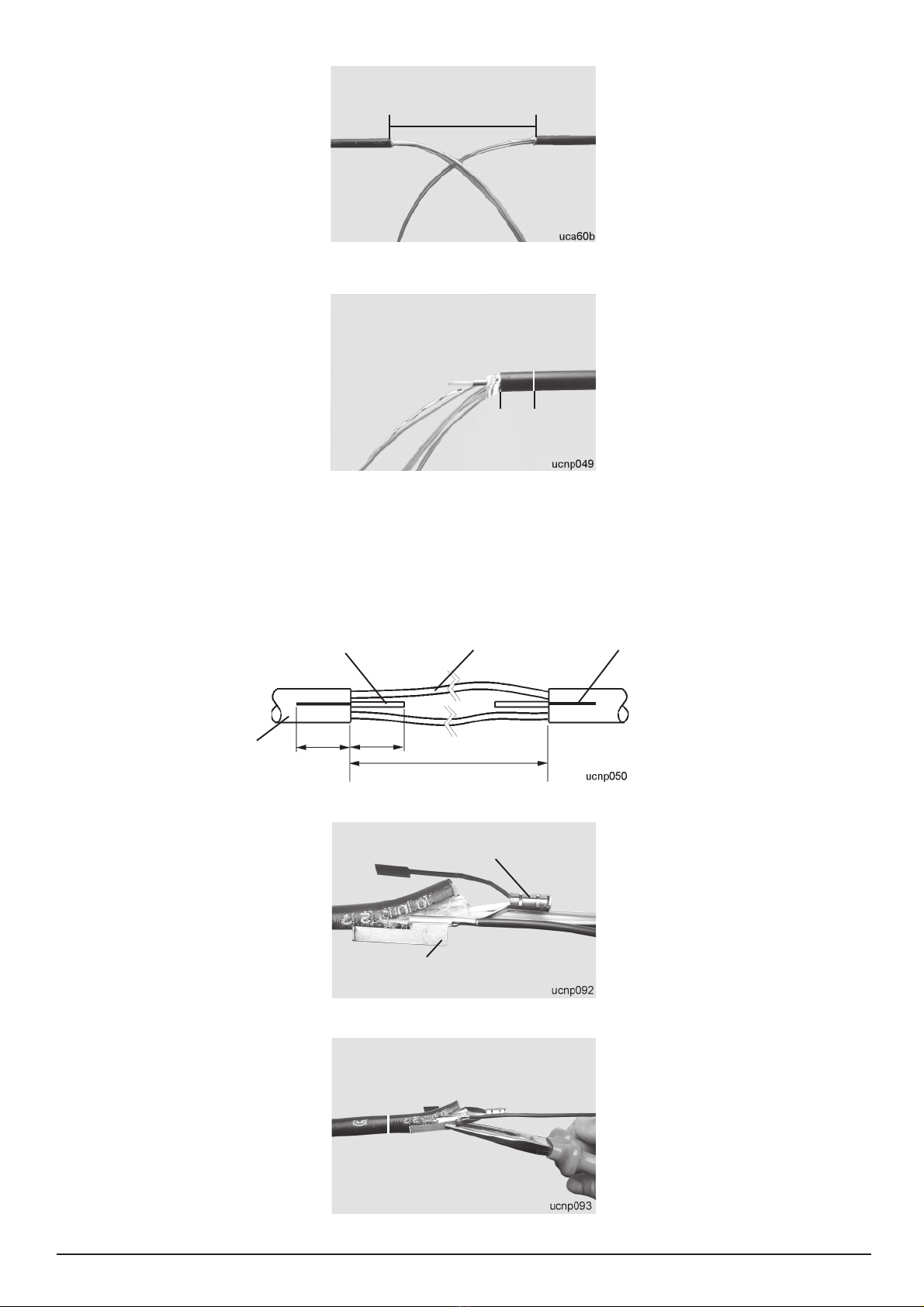
5.2 Vorbereitete Kabelenden mit
Dichtungswickel auf belegten
Dichtungskörper aufsetzen und
andrücken. Darauf achten, daß die
Kabelenden zur Innenseite des
Dichtungskörpers zeigen.
5.2 Place prepared cable ends with
sealing wrap on covered end cap and
press down. Ensure that the cable
ends point to the inside of the end cap.
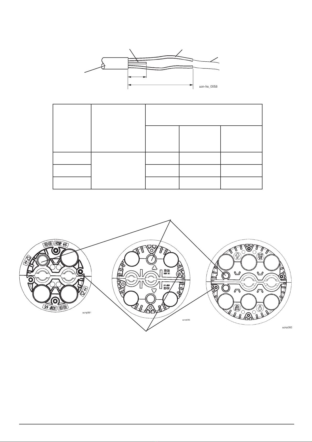
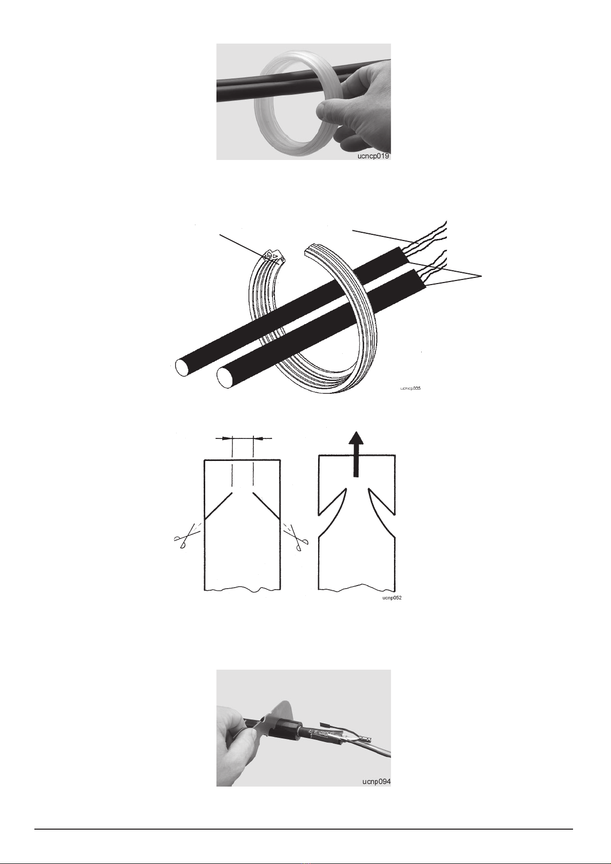
5.3 Wenn nur ein Kabel in den
Dichtungskörper eingesetzt wird, muß
die zweite Öffnung mit einem Blind-
stopfen belegt werden.
Der Blindstopfen wird in gleicher
Weise wie das Kabel mit Dichtungs-
band belegt.
Mit dem Belegen des Dichtungs-
bandes an der Markierung des Blind-
stopfens beginnen.
Den Blindstopfen mit der geschlosse-
nen Seite nach außen in den
Dichtungskörper einlegen.
5.3 If only one cable is inserted into
the end cap the second cable entry
has to be closed with a dummy plug.
The dummy plug is covered with
sealing tape in the same way as the
cable.
Start covering with sealing tape at the
marking of the dummy plug.
Insert the dummy plug into the end
cap with the closed end pointing to the
outside of the end cap.
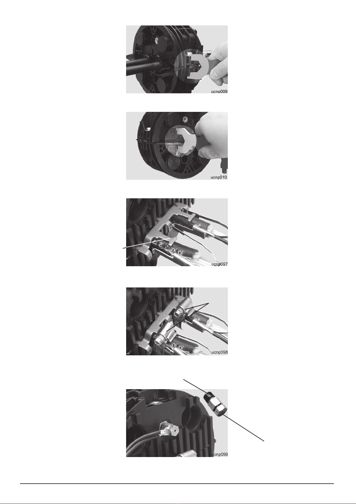
5.4 Obere Dichtungskörperhälfte
aufsetzen, andrücken und mit den
beiliegenden Schrauben mit Unterleg-
scheiben durch abwechselndes
Anziehen langsam schließen, bis die
Verschlußlehre paßt.
Achtung: Die kurzen Schrauben
außen und die langen Schrauben
innen verwenden.Keine elektrischen
Werkzeuge benutzen!
5.4 Fit upper half of end cap, press it
down and using the accompanying
screws and washers slowly close it
by tightening the screws alternately
until the closing gage fits.
Note: Use the short screws outside
and the long screws inside.
Do not use any electrical tools!
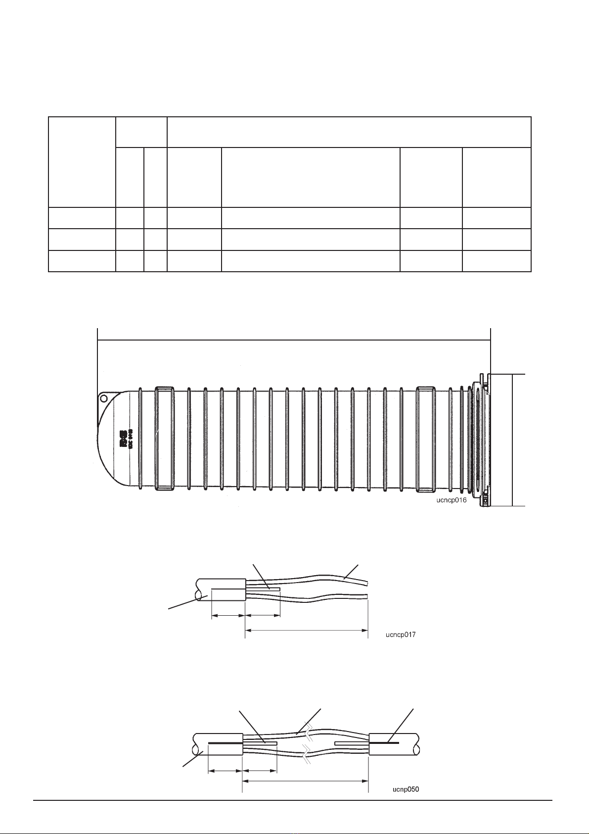
Geschlossene Seite
Closed end
25
Führungsnuten
Guide slots
Gewindehülsen
Threaded sleeves
35
Dichtungskörperhälfte
nd cap half
1
Dichtungskörperhälfte
nd cap half
2
Markierung für Dichtungsband
Marking for sealing tape
Skizze 12 / Sketch 12
10 UCNCP 5/7/9 MFT Flip
5.5 Prüfung mit der Verschlußlehre.
Achtung: Wenn die Lehre paßt,
Schrauben nicht weiter anziehen.
Prüfen des Verschlußmaßes auf der
Stirnseite.
5.5 Check with the closing gage.
Important: When the gauge fits, do
not tighten the screws any further.
Checking the closing dimension on the
front surface.
5.6 Doppelabfangungswinkel für
2 Kabel in die entsprechenden
Führungsnuten einsetzen und bis zum
Kabelmantel schieben.
5.7 Kabelenden mit Kabelschellen an
der Abfangung befestigen.
5.6 Insert double strain relief bracket
for 2 cables in the corresponding
guide slots and slide them up to the
cable sheath.
5.7 Secure cable ends to the strain
relief using cable clamps.
5.8 Erdverbindung durch Verschrau-
ben der Erdseile mit der belüfteten
Erddurchführung herstellen. Vor dem
Verschrauben Erdungsschraube mit
Dichtungspaste bestreichen und
5 Minuten ablüften lassen.
5.8 Establish ground connection by
screwing the ground wires to the
vented ground feedthrough. Before
screwing them together, brush
grounding screw with sealing paste
and leave to air for 5 minutes.
Doppelabfangungswinkel
Double strain relief bracket
Kabelschellen
cable clamps
Belüftete Erdungsschraube
Vented grounding screw
Dichtungspaste
Sealing paste