LINC PAN0RAY - DUAL DISPLAY LINC PAN0RAY - DUAL DISPLAY
8 9
OVERVIEW
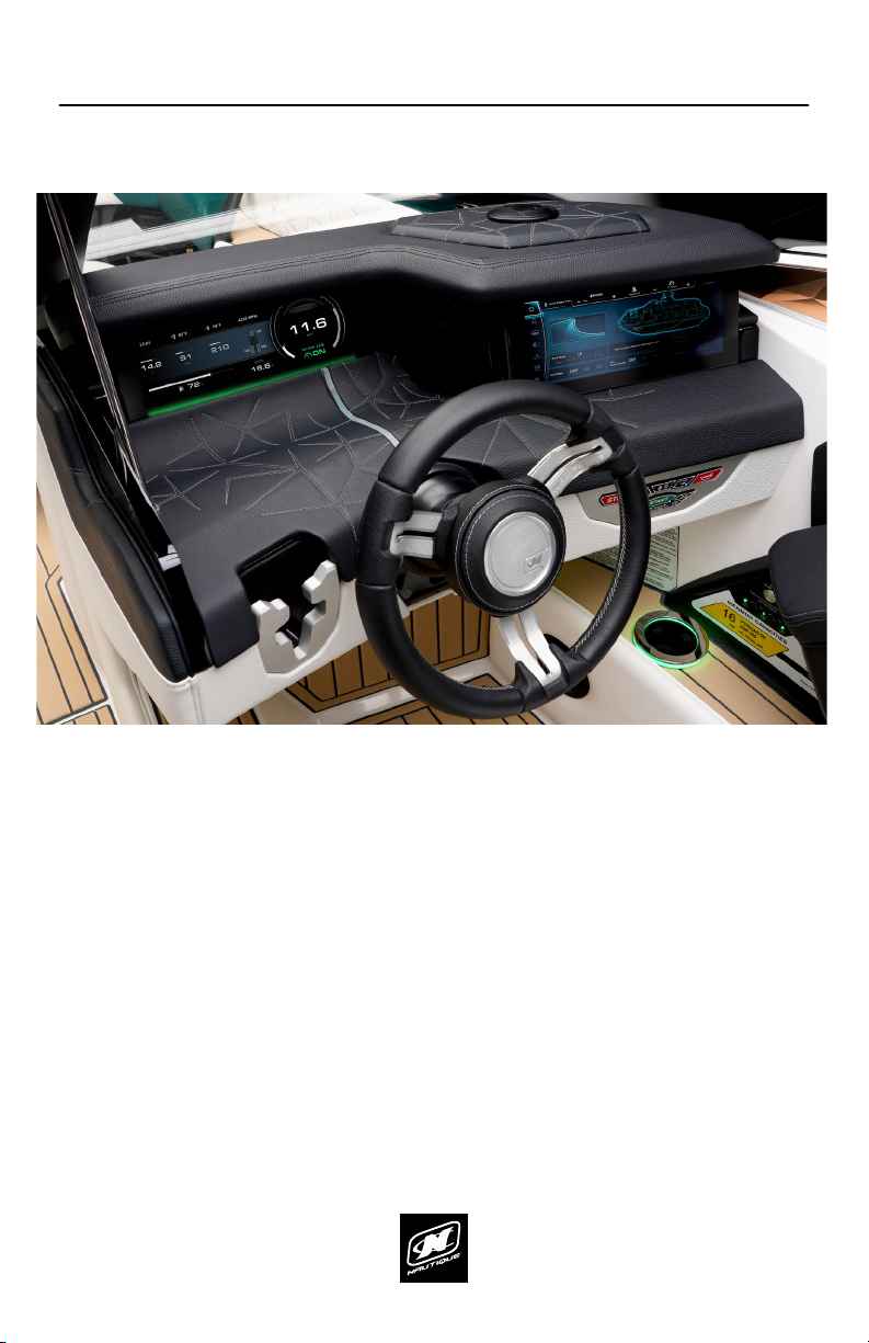
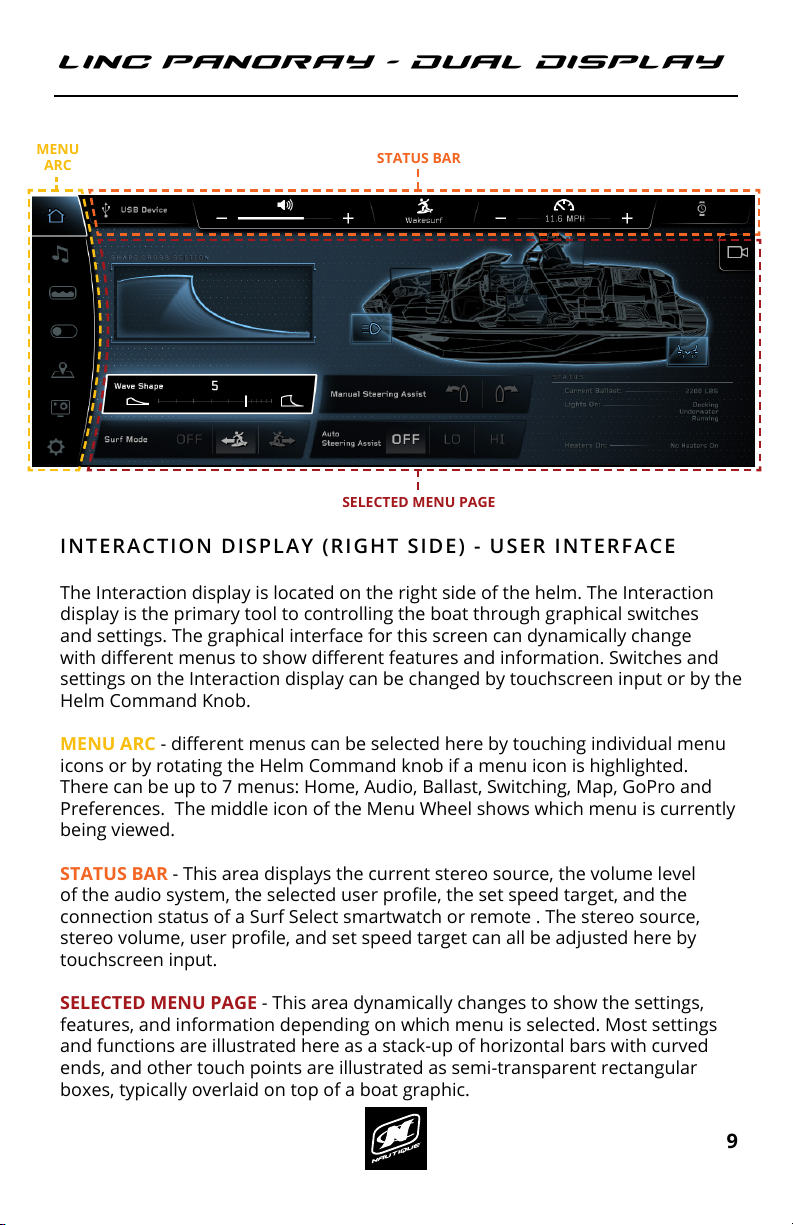
INTERACTION DISPLAY (RIGHT SIDE) - USER INTERFACE
The Interaction display is located on the right side of the helm. The Interaction
display is the primary tool to controlling the boat through graphical switches
and settings. The graphical interface for this screen can dynamically change
with dierent menus to show dierent features and information. Switches and
settings on the Interaction display can be changed by touchscreen input or by the
Helm Command Knob.
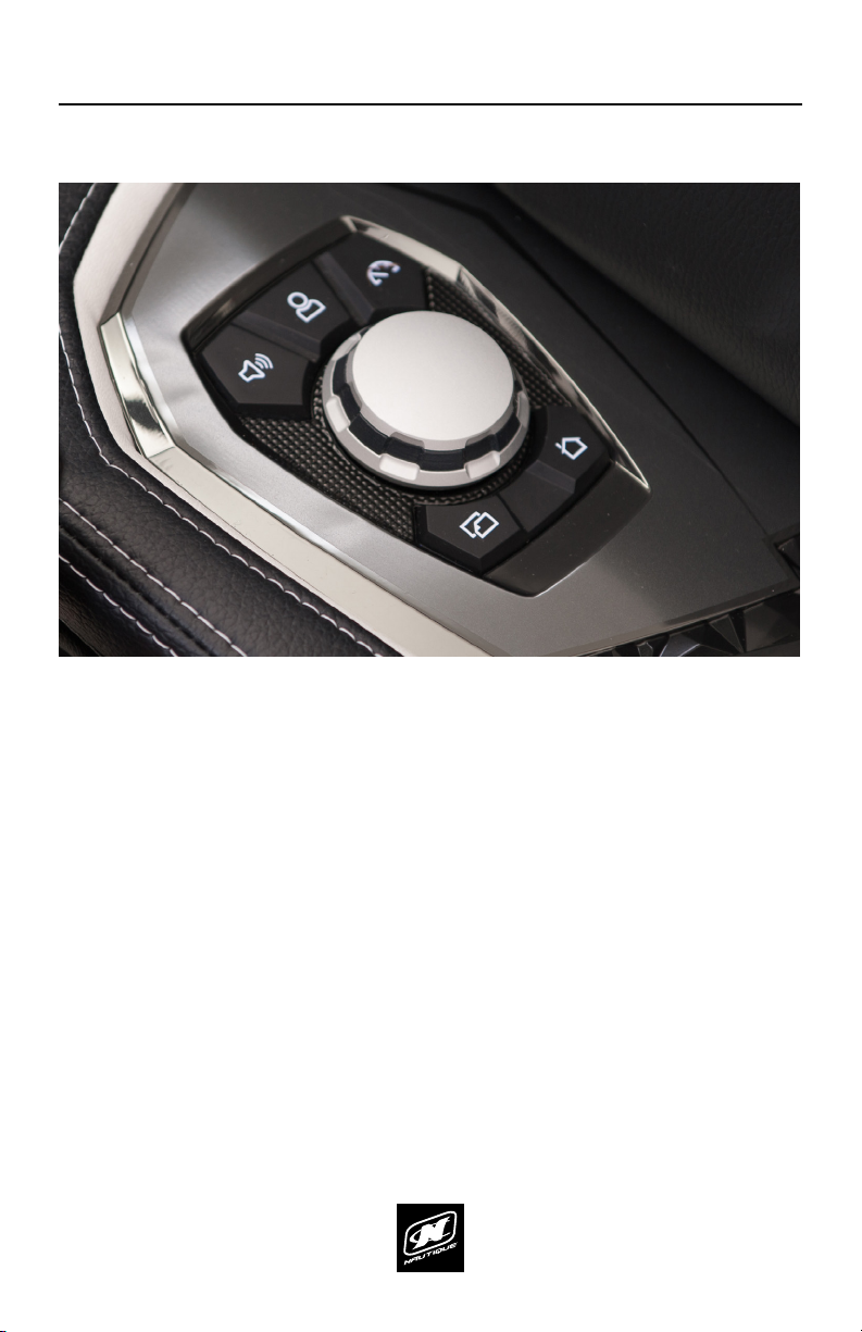
MENU ARC - dierent menus can be selected here by touching individual menu
icons or by rotating the Helm Command knob if a menu icon is highlighted.
There can be up to 7 menus: Home, Audio, Ballast, Switching, Map, GoPro and
Preferences. The middle icon of the Menu Wheel shows which menu is currently
being viewed.
STATUS BAR - This area displays the current stereo source, the volume level
of the audio system, the selected user prole, the set speed target, and the
connection status of a Surf Select smartwatch or remote . The stereo source,
stereo volume, user prole, and set speed target can all be adjusted here by
touchscreen input.
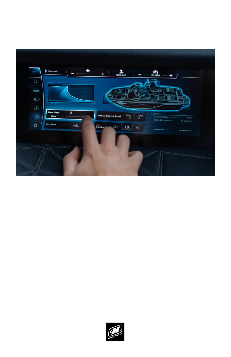
SELECTED MENU PAGE - This area dynamically changes to show the settings,
features, and information depending on which menu is selected. Most settings
and functions are illustrated here as a stack-up of horizontal bars with curved
ends, and other touch points are illustrated as semi-transparent rectangular
boxes, typically overlaid on top of a boat graphic.
GAUGE DISPLAY (LEFT SIDE) - USER INTERFACE
The Gauge display is located on the left side of the helm. This display will always
show critical gauges and information. The Gauge display is meant to provide
large information that can be conveniently seen at a glance. This display cannot
be directly controlled with touchscreen input or the Helm Command Knob.
SPEEDOMETER SECTION - displays the current speed, the set speed target,
and the current state of the speed control. In the example above, the Steering
Assist run time is shown, as a grey, segmented arc. This will only appear here if
Nautique Integrated Steering Assist is equipped; if that is not equipped, then RPM
will be shown in that location in a large format.
Please note that a green glow will appear along the bottom edge of the screen
whenever speed control is on and the set speed has been reached (as shown in
the screen above)
UPPER SECTION - displays the clock, air temperature, water temperature, and
RPM (depending on selected options).
MIDDLE SECTION - displays the voltage, oil pressure, engine temperature, and
current ballast tank levels.
LOWER SECTION - displays the fuel and depth gauges
CURRENT SPEED
SPEEDOMETER
SECTION
MENU
ARC
UPPER SECTION STATUS BAR
SELECTED MENU PAGE
SET SPEED & SPEED CONTROL ON/OFF
DEPTH GAUGE
LOWER SECTIONMIDDLE SECTION
FUEL GAUGE
LINC PAN0RAY - DUAL DISPLAY LINC PAN0RAY - DUAL DISPLAY
56 57
PREFERENCES MENU PREFERENCES MENU
Surf Select Enable* - if turned on, it allows certain settings to be
changed by someone who is riding/surng behind the boat with the Surf
Select Remote or Surf Select App on a Garmin Watch.
Display Settings - a pop-up menu that shows display settings like
brightness and the selected unit of measurement.
(See image on following pages for reference)
Clock Settings - a pop-up menu that shows clock settings like time zone,
Daylight Savings Time on/o, and 12/24 hour modes.
(See image on following pages for reference)
System Info - a pop-up menu that identies the LINC display and the
current software installed on the display.
Pair Surf Select Remote/Watch* - will pair a Surf Select compatible
remote or watch. These devices can allow a surfer/rider to switch surf
sides, change set speed, change NSS setting, change NCRS setting, or to
adjust the volume through a Pebble watch with the Surf Select App.
Power Diagnostics - a fullscreen mode that displays a list of circuit fault
codes and descriptions; the operator can reset faults here. Pressing the
back arrow will return the operator to the main Preferences page.
(See image on following pages for reference)
Engine Diagnostics - a fullscreen mode that displays a list of engine
fault codes and descriptions. On some engines, corrective action will be
shown. There is also a vertical “Fault Log” tab that will show prior stored
faults. Pressing the back arrow will return the operator to the main
Preferences page.
Dealer Menu - a fullscreen mode that displays a menu that give dealers/
technicians access to change critical settings/options for the boat. This
menu is password protected to prevent the customer from adjusting
critical boat settings that may negatively aect the operation of the boat.
In addition to these functions, there is also an Engine Hours readout located in
the top right corner.
*NOTE - some of the functions shown in above screenshot are optional and are
not equipped on every boat.
The Preferences menu contains the interface settings of both the Gauge and
Interaction display units.
River Mode - allows the driver to keep the boat’s speed-over-water
constant when a current is present. Will add extra River Mode functions
on the Home Screen for non-Paddle Wheel boats.
Auto Awareness Camera - If turned on, the video from the awareness
camera will appear on the right side of the Home Menu when the boat is
moving at lower speeds.
Speed Buzzer - the LINC unit audibly buzzes when the set speed is
achieved
Depth Buzzer - the LINC unit audibly buzzes when the boat is in shallow
waters, and buzzes when the minimum depth is reached.
Minimum Depth- sets when the Depth Buzzer goes o.
Paddle Wheel Oset* - lets the operator adjust the oset of the paddle
wheel speed input. The Paddle Wheel Oset is calibrated from the
factory, so it is recommended that the operator leave this setting alone
unless they suspect that the Paddle Wheel needs re-calibrating so that
the boat can achieve the proper speed. When in doubt, contact your
local dealer about the Paddle Wheel Oset.
FIG. M1 - THE PREFERENCES MENU