Cozzia 16019 Manual

1
中国·厦门蒙发利科技有限公司
Xiamen Comfort Science & Technology Co.,Ltd
Maintenance Service Manual
MODEL:16019
VOLTAGE SPESIFICATION: 120 V
By Customer Service Dept

2
16019 Malfunction catalog
一. Malfunction List
Common Trouble and processing Methods are listed as follow:
Error
NO Phenomenon Description Processing Methods
01 No Function
When Starting.
The Controller`s LCD Nodisplay:
① Fuse melts (in the Power Source Box or on the
main PCB).
② Power supply circuit poorly connected.
③ EMC Board fails.
④ Main PCB fails.
①Replace Fuse
②Replace Power Box.
③Replace EMC Board.
④Replace main PCB.
02 No Function
When Starting.
The Controller`s LCD Display:
① Mechanical switch fails or it’s wire is opened.
② Up or Down Stroke Photo-electricity fails.
③ Main PCB fails.
④Kneading is on without pressing any key when
starting and no response by pressing other keys.
①Replace mechanical switch or
it's wire.
②Replace Stroke Photo-
electricity.
③Replace the main PCB.
④Width Inspection Board of PCB
fails, replace it.
03 No Width
switchover.
①The terminals of Width Inspection on main PCB
and wires are poorly connected.
②The terminals of Width Inspection on massage
mechanical and wires are poorly connected.
③Width Inspection fails.
④Main PCB fails.
①&②Plug the terminal securely
or replace the wires.
③Replace Width Inspection.
④Replace the main PCB.

3
04 No Partial
Function.
①Height Inspection Terminal or
Wire Poorly Contacts.
②Height Counting Subassembly fails.
③Photo-electricity Subassembly fails.
①Plug the terminal securely
or replace the wires.
②Replace Height Counting
Subassembly.
③Replace Photo-electricity
Subassembly.
05 No Rolling. ①Terminal or Wire Poorly Contacts.
②Down-stroke Photo-electricity Subassembly Fails.
③Up-stroke Photo-electricity Subassembly Fails.
④Rolling Motor Fails.
⑤Main PCB Fails.
①Plug the terminal securely
or replace the wires.
②Replace Down-Stroke
Subassembly.
③Replace Up-Stroke
Subassembly.
④Replace Rolling Motor.
⑤Replace main PCB.
06
No kneading ①The terminals on main PCB and
wires are poorly connected.
②Kneading motor fails.
③Main PCB fails.
①Plug the terminal securely or
replace the wires.
②Replace the kneading motor.
③Replace main PCB.
07 No tapping ①The terminals on main PCB
and wires are poorly connected.
②Tapping motor fails.
③Main PCB fails.
①Plug the terminal securely or
replace the wires.
②Replace the kneading motor.
③Replace the main PCB.
08 No response when
pressing the keys on
the remote controller
①The terminals and wires are poorly connected.
②The PCB of remote controller fails.
①Plug the terminal securely or
replace the wires.
②replace the remote controller.
09 The Backrest cannot
recline or set up.
①the terminal of reclining actuator and wires are
poorly connected.
②the reclining actuator fails.
③main PCB fails.
①Plug the terminal securely.
②replace the reclining actuator.
③replace the main PCB.

4
10 The Footrest cannot
lift or recline.
①the terminal of foot rest actuator and wires are
poorly connected..
②the foot rest actuator fails.
③main PCB fails.
①Plug the terminal securely.
②replace the foot rest actuator.
③replace the main PCB.
11 No vibration by the
motors in the seat
pad.
①The vibrational motor fail
②The terminals and wires are poorly connected
or the wires fail.
③Main PCB fails.
①Replace the vibrational motor.
②Plug the terminal securely or
replace the wires.
③Replace the main PCB.
12 No kneading of the
Footrest
①The terminals are not touch well with PCB
or the wires are not connected.
②Main PCB fails。
①Plug the terminal securely or
replace the wires.
②Replace the main PCB。
14 No gas charging in
the seat-pad.
①The terminal of the snuffle valves
and wires are poorly connected.
②The snuffle valves fail.
③The inflator pump fails.
④Main PCB fails.
①Plug the terminal securely.
②Replace the snuffle valves.
③Replace the inflator pump.
④Replace main PCB.
15 No gas charging in
the Footrest
①The terminal of the snuffle valves and wires are
poorly connected.
②The snuffle valves fail.
③The inflator pump fails.
④Main PCB fails.
①Plug the terminal securely.
②Replace the snuffle valves.
③Replace the inflator pump.
④Replace main PCB.
二. Troubleshooting Process
Attention for repairing chair or replacing parts:
①Make sure the power is OFF before tearing down the wires, moving terminals or replacing parts.
②Semiconductors (such as IC and others) are very easy to be damaged by static, so when you touch
the PCB, please make sure your body is grounding (by wearing a girding static ring), or your hands
are touching with earthing grip (household electrical appliances putting to earth, such as fridges,
washers and …) to release all static of the body.
5
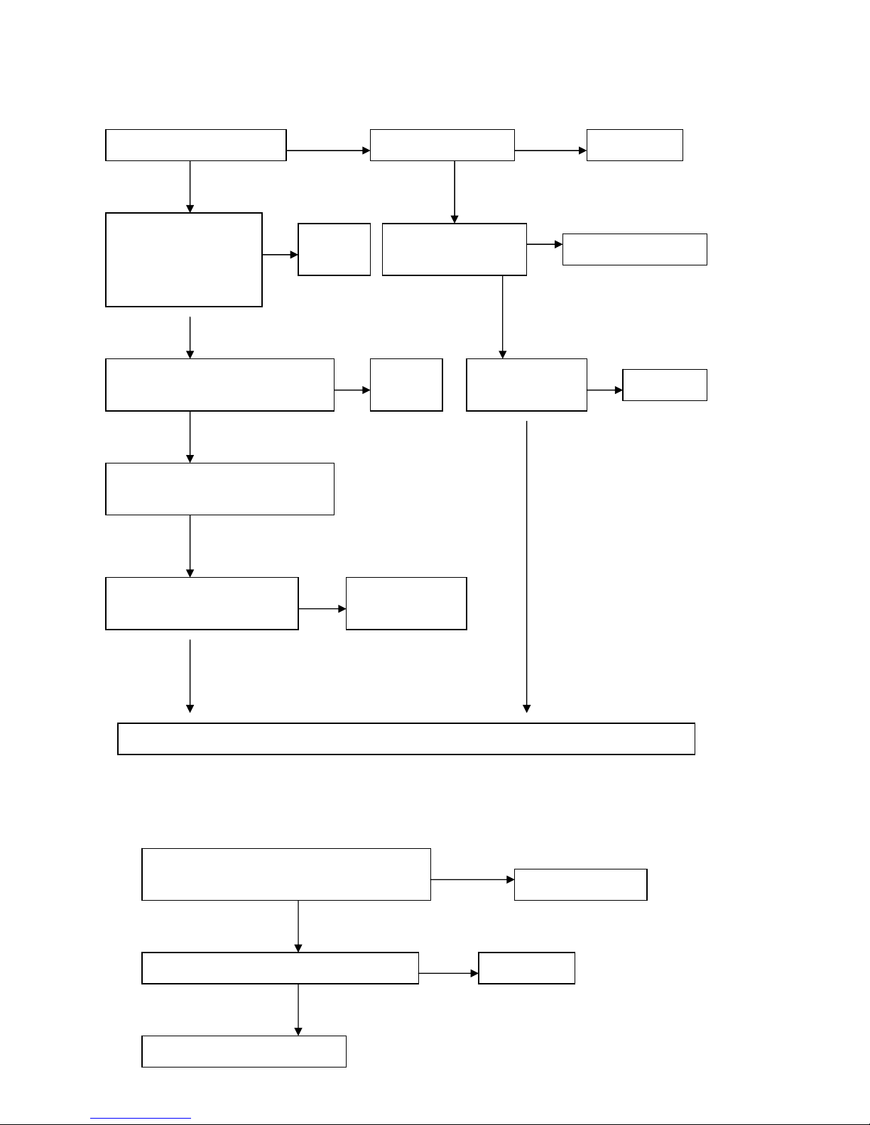
1. No function of starting.
2. No width switchover
Is the LCD illuminating? Is the fuse melted? Replace fuse.
Are the terminals of Up
and Down Stroke
Subassembly connected
securely?
Is the power cord
open-circuit? Replace power cord.
Connect
securely.
The switches of Up and Down
Stroke Subassembly fail or not?
The EMC Board
fails or not Replace it.
Replace
them
Is kneading on without pressing any
key when starting?
Width Inspection Board fails
or not?
Replace Width
Inspection Board.
Replace main PCB
Y
N Y
N
N
Y
Y N
Y
Y
N
N
N
Are the terminals of Width Inspection Board
and main PCB connected securely? Connect securely.
Width Inspection Board fails or not? Replace it.
Replace main PCB.
N
Y
Y
N

6
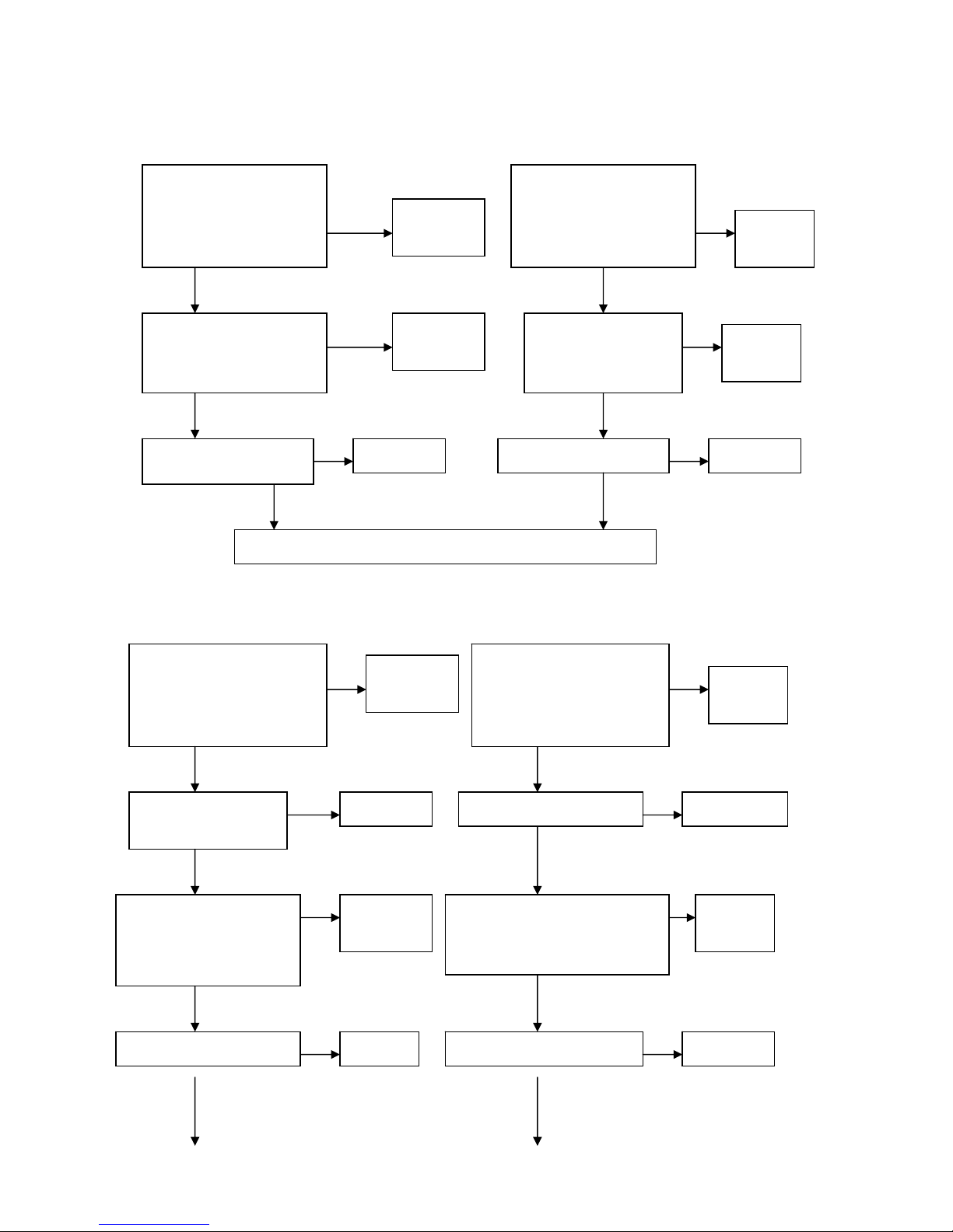
3. No function(fixed-spot or partial)
否
是
4. No rolling
5. No kneading.
Are the terminals of Height Inspection
Board and main PCB connected securely?
Connect securely.
Height Inspection Subassembly fails or not? Replace it.
Replace Main PCB.
Y
N
Y
N
Are the terminals of rolling motor wire and
main PCB connected securely? Connect securely
Rolling motor fails or not Replace the motor
Up stroke Photo-electricity subassembly fails or not Replace it
Down stroke Photo-electricity subassembly fails or not Replace it
Replace main PCB
N
Y
Y
Y
Y
N
N
N
Are the terminals of kneading motor wire
and main PCB connected securely? Connect securely.
Kneading motor fails or not?
Width Inspection Board fails or not?
Replace the motor.
Replace it.
N
Y
Y
N
N

7
6. No tapping.
7、The key of the remote comtroller was not function
8. Actuator doesn’t work.
Replace main PCB.
Are the terminals of tapping motor wire and
main PCB connected securely? Connect securely.
Tapping motor fails or not? Replace the motor.
Replace main PCB.
N
Y
N
Y
Are the terminals of remote controller
wire and main PCB connected securely? Connect securely.
The conductive rubber fails or not? Replace it.
Replace the remote controller.
Y
N
N
Y
Are the terminals of
reclining actuator and
main PCB connected
securely?
Connect
securely.
Are the terminals of
foot rest actuator for
foot rest and main PCB
connected securely?
Connect
securely.
The reclining actuator
fails or not? The foot rest actuator
fails or not?
Replace it.
Replace main PCB.
Replace it.
Y
NN
Y
NN
Y
8
9. NO vibration
10. No gas charging
Y
Are the terminals of
print motors in the seat
pad and main PCB
connected securely?
Are the connectors in the
middle of the wire
connected securely?
Are the terminals of print
motors in the calves-rest
and main PCB connected
securely?
Are the connectors in
the middle of the wire
connected securely?
Replace main PCB.
Connect
securely. Connect
securely.
Print motor fails or not? Print motor fails or not?Replace it. Replace it
Connect
securely. Connect
securely.
N
Y
N
N
N
Y
Y
Y
Y
N
N
Are the terminals of snuffle
valve for bags in the seat
pad and main PCB
connected securely?
Snuffle valve fails or
not?
Are the terminals of snuffle
valve for bags in the Foot
Rest and main PCB
connected securely?
Snuffle valve fails or not?
Connect
securely. Connect
securely.
Are the terminals of
inflator pump and main
PCB connected securely?
Replace Replace it.
Replace it. Replace it.
Are the terminals of inflator
pump and main PCB connected
securely?
Connect
securely.
Connect
securely.
Inflator pump fails or not? Inflator pump fails or not?
Y
N
Y
Y
N
N
Y
N N
N
Y
Y
N
Y
N
Y
9
Common trouble about electric control and processing methods of this chair are mentioned above. It
is for indication only.
三. PF53197 Disassembly process
Please make sure the massage chair is POWER OFF before maintenance and repair.
As the voltage specification is 220V AC, please make sure the plug is removed from
outlet for safety before processing operations as follow
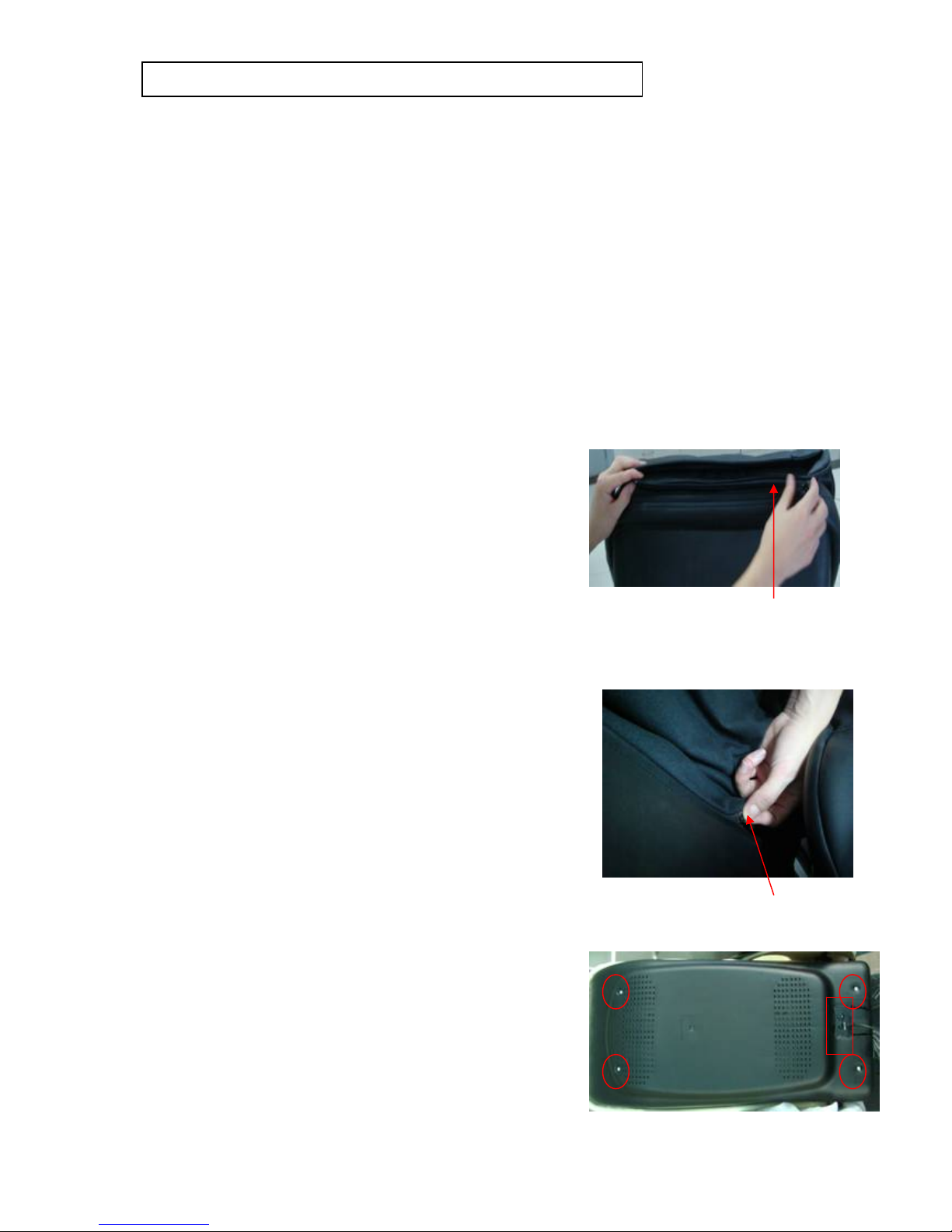
1:Disassembly of the back pad
①You can find a zip on the top of the back rest.
②Unzip, then the back pad can be removed.
③You should be replace if it was damaged
2:Replace the Sponge pad
A:You can see the Sponge pad after removed the back pad
B:the zip is on the left of below
C:Unzip of the sponge pad and replace it if you need
3. Replacement the rear cover of backrest
If disfiguring damage or crack happened, you can proceed as follow:
A:Find 4 pcs screws on the rear cover and 4 pcs screws on the
power switch, then Slacken and remove them (8PCS)
with a plus screwdriver.
Unzip of the sponge pad
Using the plus screwdriver
screw off 8pcs screws
Replace main PCB.
Unzip of the back pad

10
B:Please remove rear cover after removed power switch
C:You should be replaced if it was damaged
4:Disassembly of the front cover of back rest
If disfiguring damage or crack happened, or the inside
cloth is damaged, you can proceed as follow:
A:After removed the rear cover,
You can find 4pcs screws on the backrest with the front cover
B:Removed front cover after screw off the screws
C: You should be replace if it was damaged
5:Disassembly of the motors :
The voltage of this massage chair is high and the motors arerotating in high speed,
so make sure the power is OFF before disassembly.
For safety, you should remove plug from outlet.
Attention:Disassemble the rear cover of the back rest only, before disassembling the motors.
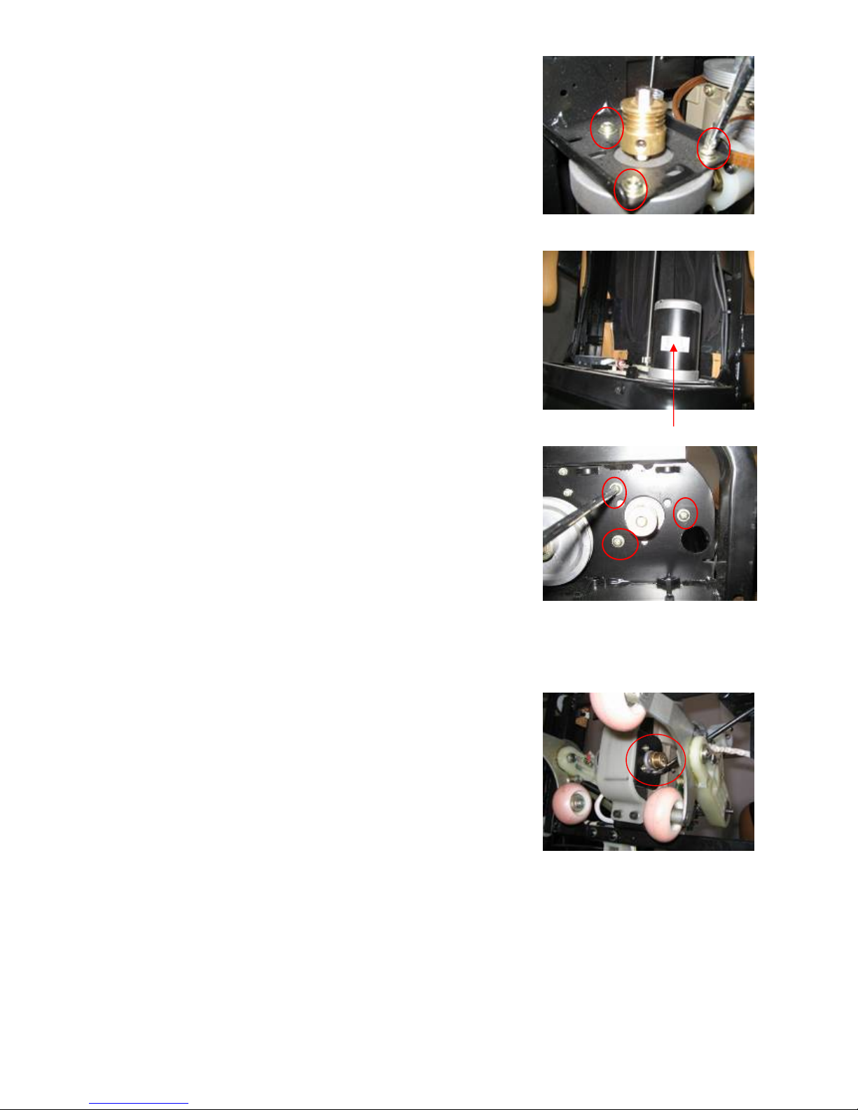
5.1 Kneading motor:
A :Disassembled the rear cover of the Back rest,
then take off the belt at the top massage mechanism
B :Find the wire of kneading motor,
Cut off the cable ties tightenin and contact nipple covering with wire,
Then disconnect the two wires
Take off the belt
Using plus screwdriver
screw off 4pcs screws
11
C :On the kneaking motor have 3PCS fixing screws
Just screw them that take off the motor,and replace it if you need
5.2 Rolling motor:
A :Release the stopper at the bottom of back rest,
Recline the back rest forward for disassembling the motor easily.
B:The rolling motor at the bottom of back rest.,
Take off the rolling belt at the bottom of motor
C: Disassemble ways as the same as the kneading motor
5.3 Tapping motor:
The tapping motor at behind the massage mechanism
Disassemble methods as the same as the kneading motor or rolling motor,
But you feel is difficult screw off screws,
please disassemble the swimming arm(a side of screws motor )
(If you need ,see disassemble the swimming arm part 6.2)
The rolling motor
Screw off the tapping
motor`s screws
Screw off the screws(3pcs)
Screw off the screws(3pcs)
12
6:Disassembly and replacement of massage mechanism
Disassemble the rear and front cover of the Back rest before disassembling the massage mechanism.
6.1 The belowe steps is the replace of massage mechanism
A. Remove the nipples tightening the wires of kneading and tapping
motors ,and disconnect the wires. Then cut off all the cable ties whith
this wires
B. Pull out the terminal of width inspection board.
C. Take off the belts of the kneading motor and tapping motor
Slacken and remove the 4 pieces of screws fixing the massage mechanism
to the frame with inner hexagon spanner(5mm).
D. You maybe don`t get it out because of the screw bolt.
So rotate the big belt wheel to adjust the width of swinging arms until you can get it out easily.
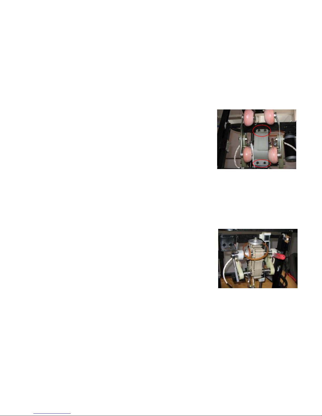
6.2 Disassemble the swinging arms and universal rods:
NOTE: You don’t have to disassemble the massage mechanism
If you just disassembling the swinging arms.
A.Slacken and remove the hexagon check nut tightening the universal
rod assembly to eccentric shaft with a hexagonal socket wrench(1/2).
B.Remove the hexagon check nut and washer, so you can
separate the swinging arm and universal rod from the massage mechanism.
C.Remove the tension spring, and further disassembly can be done
Attention:When slackening the hexagon check nut tightening the universal
rod assembly to eccentric shaft, you can’t loosen it for the rotating shaft.
So the eccentric shaft should be fixed. What you should do is inserting
an iron rod into the hole of the shaft to stop its rotating.
Remove the hexagon check
Screw off the inner hexagon(4pcs)
13
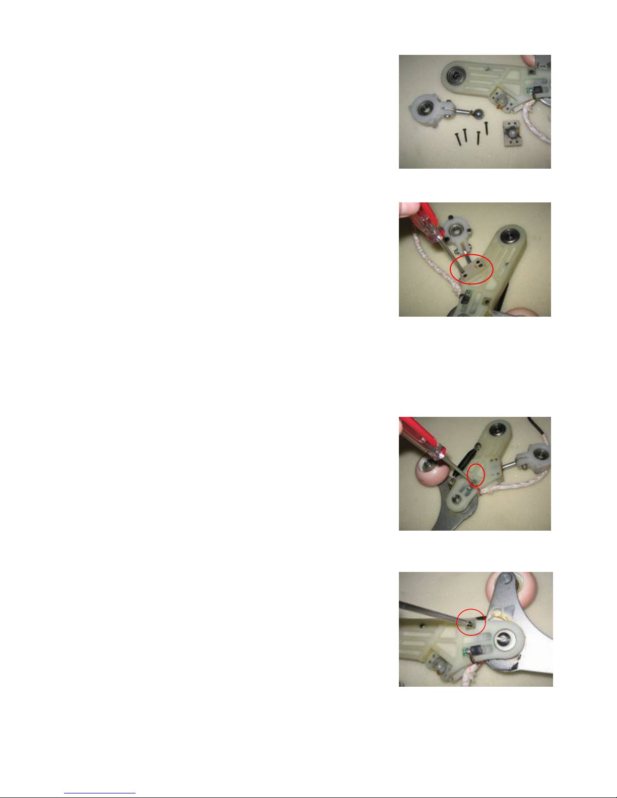
6.3 Disassembly of the universal rod:
A.Slacken and remove the screws tightening the plastic cover
to the winging arm with a plus screwdriver
if any parts need replacing.
B:Remove the plastic cover, so you can separate the universal rod
form the swimming arm.
C: Slacken and remove the screw bolt tightening the flat end to the plastic
bearing block with a shifting spanner and a plus screwdriver.
6.4 Replace the optocoupler of body type checkout
Note: You just disassemble the rear and front covers of the backrest
before disassembling the optocoupler of body type checkout.
A.Slacken and remove the screw tightening the optocoupler
to the swimming arm with a plus screwdriver
B: Disassemble the optocoupler on the other swinging arm
in the same way; Now ,you can replace it.
C: You can disassemble the optocouplers in the way mentioned
above if the wires need replacing.
6.5 Replacement of the shock pad
A: Find the screw tightening the shock pad to the swinging arm.
B: Slacken and remove the screw with a plus screwdriver, so you can replace it.
C: Proceed in the reverse order of disassembly when replacing a new one
Slacken the screws and take out
the ball top of rod
Take off the screws
and universal rod
Slacken the screws
Slacken the screws

14
6.6 Disassembly of the holder of knead balls
A:It is unnecessary to disassemble the massage mechanism to
replace the holder of knead balls, just disassemble the rear
cover of the Back rest.
B: Slacken and remove the screw bolt tightening the holder to
the swinging arm with a hexagonal socket wrench (10 mm)
and a minus screwdriver.
Pull the screw bolt out, and the holder can be removed.
C: Remove the tension spring and a new holder can be replaced if needed.
D: Proceed in the reverse order of disassembly when replacing a new one.
6.7.Disassembly of the knead balls
A: Slacken and remove the hexagon check nut tightening the knead balls
to the holder with a hexagonal socket wrench(1/2).
B: Replace a new knead ball and tighten the hexagon check nut.
Attention: There is a plastic washer between the wheel and the nut.
。
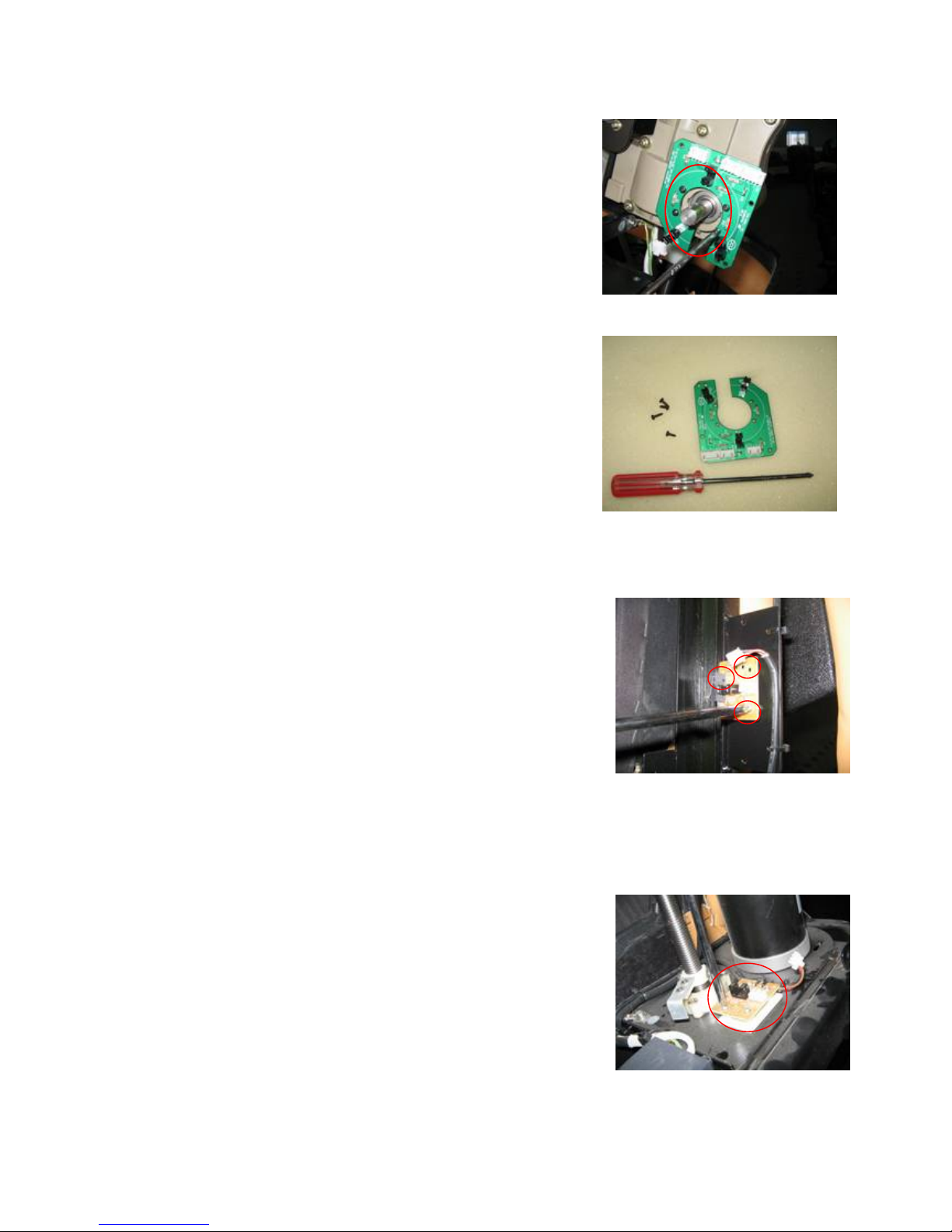
6.8.Disassembly of width inspection board
A:Pull out the terminal of width inspection board.
B:Disassemble the left swimming arm
C:Slacken and remove the screw bolt tightening the light barrier to
the eccentric shaft with shifting spanner and inner hexagon spanner,
then the eccentric shaft can be removed.
D: Slacken and remove the screws tightening the width inspection board
to the reduction gear box:
E: Proceed in the reverse order of disassembly if the width inspection board
Take off the ball
Drive the screw bolts and nuts
Tools and parts
Disassemble the holder of
knead balls
15
or light barrier needs replaced.
Attention:In order to operate conveniently,
you can disassemble the massage mechanism first,
then disassemble the width inspection board.
7.Disassembly of Photo-electricity Subassembly:
7.1. Disassembly of up /down stroke photo-electricity subassembly
A: Disassemble the Photo-electricity Subassembly is easier
Just slacken the screws(3pcs) and pull a terminal of the wire
B: There are on the backrest side
Attention: Generally speaking, the Stroke Photo-electricity
Subassembly is so stabile that it can’t be damaged easily.
7.2. Disassembly of the counting Photo-electricity Subassembly
A:Disassemble methods as the same as 7.1
B:There is at the bottom of backrest
width inspection board
and tools
Slacken the screws
Terminal of the wire and 3pcs screws
Terminal of the wire and 3pcs screws

16
8:Disassembly of bearings and bearing blocks
A:Disassemble the rear and front covers of the back rest.
B:Slacken and remove the screws tightening the sheet-metal to
the frame with a plus screwdriver.
C:Remove the sheet-metal, so you can pull out the bearing block. Turn the block clockwise and
counterclockwise alternately to pull it out easily.
9. Disassembly of the seat part
9.1 Replacement of the armrest
A:Slacken and remove the socket head screws tightening
the armrest with a inner hexagon spanner.
B:Replace a new one, and tighten the screw bolts.
9.2 . Replacement of the decorative board
A:Find the screws at the side of decorative board
There are 3pcs inner hexagon screws
B:Slacken and remove inner hexagon screws
Then you can take it down if need replace
9.3 Replacement of the seat pad
A:Raise seat pad begin behind of seat。
Raise seat pad
Slacken the screws(6pcs)
Slacken the screws(2pcs)
Slacken the screws(3pcs)

17
B:Pull out the Connector of air hose
and vibrational motor wires
then take off the fixing material
D:Now, you can replace new one if it need
9.4 Replacement of the side boards
A:disassemble the armrest above the side board
needing replacement
B:Find the inner hexagon screws (4pcs) ,then slacken them
And take down
C:Now,you can replace a new one.
9.5 Replacement of main PCB
A:Main PCB box Under the seat, just disassemble board and Raise it
B:Then,you can find 4pcs screws around box
Slacken these screws and take the cap
Inside board have 4pcs inner hexagon screws
Commector of air hose
and motor wires
Take off the fixing material
Slacken the screws(4pcs)
Slacken the screws(9pcs)
Take the box cap

18
C: Pull out all the terminal connecting to the main PCB,
unlock the plastic posts for the PCB. and a grounding screw
Then the PCB can be removed.
F:Proceed in the reverse order of disassembly
when replacing a new PCB.
9.6 Replacement of the reclining actuator of the Back rest
A:Turn off the power and remove plug from outlet.
Lay the back rest forward on the Seat Pad.
Pull out the splint pin in the pin rollwhich connects the reclining actuator of
the Back rest and the turnover mechanism with a nipper pliers.
Then draw the pin roll to free one end of the actuator.
B: Release the other end of the actuator in the same way as”A”
C:Disassemble the upper cover of the box for the main PCB,
then pull out the terminal of the actuator.
D: First, fix both end of the actuator in the reverse order of Part A&B.
Don’t forget to assemble the bush rings in the both end of actuator as
you can see in disassembly.
The terminal of reclining actuator
Reclining actuator and the accessory
The screw is
grounding point”
The plastic posts
taken down
the another Pin roll
taken down the Pin roll

19
E:Then connect the terminal of the actuator to the main PCB.
Turn the power on and check the connection is right
or not by sitting up or reclining the Back rest.
If it’s not, just exchange the two pin of the terminal.
F:At last, assemble the box of the main PCB,
and tighten the wire of the actuator with cable ties.
9.7 Replacement of the foot rest actuator
A:Turn off the power and remove plug from outlet.
Lay the Back rest forward on the Seat Pad.
B:take off the splint pin in the pin roll which connects the
legrest actuator with a nipper pliers ,then separate the
actuator with legrest
Attention: When drawing the pin roll, you should hold the LegRest with
you leg or by another person. Because the LegRest maybe
fall down on your foot
C:Then.take off the splint pin of seat part,and separate the actuator with seatrest
D:Last, just you take off the terminal of actuator on main PCB
Now,you can take out the actuator and replace it
The terminal of the actuator
Tade out the actuator of legrest
Axis
Axis pin
Take off the splint pin
Separate the actuator with legrest
Take off the another pin
Separate the actuator
with seatrest

20
9.8 Replacement of the inflator pump and snuffle valves
A:Turn off the powe, then removed the seat pad and disassemble seat board
Now ,you can look at the inflator pump
B:Pull out the rubber poles fixing the inflator pump,
Take out the erminal of the inflator pump and
the terminal of the snuffle valves
10. Replacement of the LegRest
Please follow the steps below to disassemble the LegRest:
A:Turn on the power, Raise the legrest to the extreme position
for the easier disassembly.
Turn legrest back up and take the screws。
B:take out the side cover of legrest,then take off the splint pin(2pcs)
And legrest on the actuator of legrest(1pcs)
the rubber poles
Screws(3pcs)
The inflator pump
The terminal of
the inflator pump
The terminal of
the snuffle valves
Take off the splint pin
(another side has one also)
Take out the cover
Table of contents
Other Cozzia Massager manuals

Cozzia
Cozzia Renew Instruction Manual

Cozzia
Cozzia Revive OG357 User manual

Cozzia
Cozzia CZ-328 User manual

Cozzia
Cozzia CZ-710V User manual

Cozzia
Cozzia CZ-641 User manual

Cozzia
Cozzia EC-618 User manual

Cozzia
Cozzia Espree User manual

Cozzia
Cozzia EC-360D User manual

Cozzia
Cozzia CZ-357 User manual

Cozzia
Cozzia CZ-681 User manual

Cozzia
Cozzia CZ-357 User manual

Cozzia
Cozzia MC-520 User manual

Cozzia
Cozzia CZ-330 User manual

Cozzia
Cozzia ZEN CZ-641 User manual

Cozzia
Cozzia ergotec AG-6100 User manual

Cozzia
Cozzia 16027 User manual

Cozzia
Cozzia CZ-630 User manual

Cozzia
Cozzia EC-326G-CO Manual

Cozzia
Cozzia CZ-730/Qi User manual

Cozzia
Cozzia EC-362B User manual


