CPS COLOR COROB D50 User manual

COROB™ D50
Version 1.0 - R0 (October 2006)
Document Code: DU006C0100X5702
Manual Dispenser USER'S MANUAL ENGLISH
Machine à teinter
manuelle MANUEL D’UTILISATION FRENCH FRANÇAIS
Ручной дозатор РУКОВОДСТВО ПО
ЭКСПЛУАТАЦИИ RUSSIAN РУССКИЙ
Dispensatore
Manuale MANUALE D’USO ITALIAN ITALIANO
Dispensador Manual MANUAL DO USUÁRIO PORTUGUESE PORTUGUÊS
Dosificador Manual MANUAL DEL USUARIO
Versión resumida SPANISH ESPAÑOL
Manuelle
Abtönmaschine
BEDIENERHANDBUCH
Gekürzte Ausgabe GERMAN DEUTSCH
Χειροκίνητος
Διανεμητής
ΕΓΧΕΙΡΙΔΙΟ ΧΡΗΣΤΗ
Περιληπτική έκδοση GREEK ΕΛΛΗΝΙΚH
Ръчен дозатор РЪКОВОДСТВО ЗА
ЕКСПЛОАТАЦИЯ
Съкратена версия
BULGARIAN БЪЛГАРСКИ
Manuální dávkovačUŽIVATELSKÁ PŘÍRUČKA
Stručná verze CZECH ČESKY
Dozatorul Manual MANUALUL
UTILIZATORULUI
Versiunea prescurtată
ROMANIAN ROMÂNĂ
Ruèni dispenzer UPUTSTVO ZA UPOTREBU
Skraæena verzija SERBIAN SRPSKI


ENGLISH Version 1.0 - R0 (October 2006)
COROB™ D50
Manual Dispenser
User's Manual
3.17 Quart (3.0 Liter) Glass Filled Nylon or Stainless Steel Canisters
3 Oz (100 ml) Maximum dispense Pumps
Equipped as standard is a Smart Gauge for fractional incremental dispensing
Ergonomically designed valve handles - Unique single hand operation for easy use
Available in both Countertop and Floorstand models

COROB™ D50
© 2006 CPS Color Equipment S.p.A.
User’s Manual
Manual Dispenser
COROB™ D50
Version 1.0 - R0 (October 2006)
© COPYRIGHT 2006, CPS Color Equipment S.p.A. All rights reserved.
No part of this manual may be reproduced in any form, or by any means, electronic or mechanical, including
photocopying and recording, without prior written permission of CPS Color Equipment S.p.A.
Information in this manual is subject to change without notice and does not represent a commitment on the
part of CPS Color Equipment S.p.A.
Unless otherwise indicated, all references to companies, names, data and addresses used in the screens
and/or examples are purely coincidental and serve only to clarify the use of the COROB™ product.
CPS Color Equipment S.p.A. shall not be liable for technical or editorial errors or omissions made herein; nor
for incidental or consequential damages resulting from the performance or use of this material.
If you require additional copies of this manual or further technical information about it, please write to:
CPS Color Equipment S.p.A.
Via Agricoltura 103 •41038 San Felice s/P •Modena •Italy
Phone: + 39-0535-6633 •Fax: + 39-0535-663400

3
CONTENTS
1INTRODUCTION .......................................................................................................4
1.1 CARE FOR YOUR MACHINE! .................................................................................5
2UNPACKING .............................................................................................................6
3ASSEMBLY INSTRUCTIONS ......................................................................................7
3.1 Step 1 - Preparation for assembly.........................................................................7
3.2 Step 2 - Agitation assembly.................................................................................7
3.3 Step 3 - Mounting canisters.................................................................................8
3.4 Step 4 - Mounting the can shelf............................................................................9
4PRIMING THE MACHINE.........................................................................................11
5TINTING INSTRUCTIONS .......................................................................................12
5.1 Dispensing from the cylinder.............................................................................. 12
5.2 Automatic drip control piston ............................................................................. 12
5.3 Tinting instructions........................................................................................... 12
5.4 Smart Gauge................................................................................................... 14
6MAINTENANCE.......................................................................................................15
6.1 Daily Maintenance............................................................................................ 15
6.2 Periodic Maintenance........................................................................................ 15
6.2.1 Lubricating the piston............................................................................... 16
7TROUBLESHOOTING...............................................................................................17
8PROBLEM SOLVING................................................................................................19
8.1 Dripping colorant ............................................................................................. 19
9SERVICE & REPAIRS ..............................................................................................20
9.1 Dripping colorant ............................................................................................. 20
10 GAUGE CALIBRATION ............................................................................................21
11 AGITATION ............................................................................................................23
11.1 Manual agitation .............................................................................................. 23
11.2 Automatic agitation .......................................................................................... 23
12 REPLACING CANISTER ASSEMBLY..........................................................................25
13 REPLACING PUMP ASSEMBLY.................................................................................26
14 THE DISPENSING GAUGES .....................................................................................27
14.1 What are gauges? ............................................................................................ 27
14.2 Standard dispensing gauges .............................................................................. 27

4
COROB™ D50
1INTRODUCTION
This COROB™ D50 Manual Dispenser is a precision measuring device and should be treated as
such.
When operated and maintained in conjunction with the instructions contained within this manual,
the equipment will provide a long and trouble free life.
To ensure your complete satisfaction, please familiarise yourself with all maintenance and
operating instructions.
Please keep this manual available for reference and training of new store personnel.
This unit features:
•Memory gauges - Only need to set the gauge once for repeat multiple can dispensing
•Non magnetic stainless steel pump cylinders - Durable, corrosive resistant
•Long wear Teflon Seal - Durable, solvent resistant
•Automatic Drip Control Piston - Assures clean dispensing nozzles
•Retractable Sealing Arm - Stops drips, keeps work area clean
•Automatic electric timer controlled agitation - Saves time, easier canister refilling
•Stepped “Assured” agitation paddle - Consistent thorough mixing of colorant
•Removable Nozzles - Various sizes of “easy clean” nozzles available
•Glass filled Nylon canister shell - Easy clean-up
Turntable with
Machine Canisters
Floorstand with
can shelf
Carousel Index Lever
Agitation Mode
Selector Switch

5
1.1 CARE FOR YOUR MACHINE!
DO keep the machine clean and practice good housekeeping to promote accuracy in colour dispensing.
DON’T use the pump as a handle while rotating the turntable. Grab the edge of the turntable to rotate it.
DO keep the D50 User’s Manual to assist in regular maintenance and training of new personnel.
DON’T use metal or hard objects to clear blocked nozzles. Nozzles are easily removed for cleaning. Damage
to valve barrel will result from using hard objects to clean nozzles.
DO keep nozzles clean to prevent drying colorant from blocking and making dispensing difficult.
DON’T let the gauge drop down freely, as this can affect calibration.
DO lower gauges manually back into end cap, to protect them from damage.
6
COROB™ D50
2UNPACKING
The dispenser has been carefully inspected and the pumps calibrated to measure colorant with a
high degree of accuracy.
It should be carefully examined upon arrival to determine that the unit shows no signs of freight
damage. If any parts are found to be broken or damaged, immediately contact the carrier and
arrange for an inspection of the concealed damage.
Claims for damage must be made by you, the consignee, and not the shipper. The carrier
accepts full responsibility for the safe delivery of merchandise upon pick-up from the shipper.
Please read all instructions before using the dispenser.
FLOOR STAND MODELS
Floor stand units shipped: COUNTER TOP MODEL
Counter top units shipped:
12 x Assembled Canister and Pump Assembly Or 12 x Assembled Canister and Pump Assembly Or
16 x Assembled Canister and Pump Assembly Or 16 x Assembled Canister and Pump Assembly Or
20 x Assembled Canister and Pump Assembly Or 20 x Assembled Canister and Pump Assembly Or
24 x Assembled Canister and Pump Assembly 24 x Assembled Canister and Pump Assembly
1 x Floor stand 1 x Counter top
1 x Adjustable tray and hardware 1 x Agitator plate
1 x Agitator plate 1 x Turn Table
1 x Turn Table 1 x Cover Plate
1 x Cover Plate 1 x Crank Shaft
1 x Crank Shaft
1 x Bag of canister mounting screws
Check the contents as you unpack. If any parts are missing, contact your supplier as soon
as possible. Do not commence set-up until all required parts are available.

7
3ASSEMBLY INSTRUCTIONS
Prior to assembling your unit, prepare adequate working area to easily work with and
operate your machine.
For “Countertop” model, base may be placed in desired location and begin assembly
procedures at step 5.
For “Floor stand” model, begin assembly procedures at step 1.
Improper installation of the grounding plug can result in a risk of electrical shock.
If repair or replacement of the cord is necessary, ensure that the wire with insulation
having an outer surface that is green with or without yellow stripes is grounded properly.
Check with a qualified electrician or serviceman if the grounding instructions are not
completely understood, or if in doubt as to whether the product is properly grounded.
DO NOT PLUG UNIT IN UNTIL ASSEMBLY IS COMPLETE.
3.1 Step 1 - Preparation for assembly
1) Remove the packaging from the unit taking care not to cause any damage to unit.
2) Locate unit in area where it is to operate from. Machines are available in both 110V and
220V; ensure line voltage is suitable for your machine. Machine voltage rating can be found
on the data label on the machine.
3.2 Step 2 - Agitation assembly
1) Remove Nut Turntable (12) by rotating anticlockwise from the centre Top Plate of the
assembly.
Do not remove shoulder nylon bushing or support washer.
2) Remove Turntable (31) from its packaging and place on unit locating centre with Brass Swivel
Nut (Figure 3-1), (Shoulder Nylon Bushing and Support Washer should be already in place on
the Brass Swivel Nut).
3) Once the Turntable is in place, fasten Turntable Nut (12) on Brass Swivel Nut (Figure 3-1).
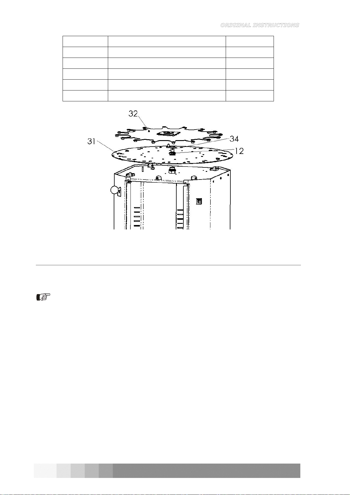
4) Insert Crankshaft and Nylon Washer (34) into centre of Brass Swivel Nut (9) (Figure 3-1).
5) Place Agitator Plate (32) on top of Turntable locating the centre with the Crankshaft (Figure
3-1).
6) Plug into mains supply and turn the Agitation selector switch to manual (position 1) (chapter
11). The agitation plate should oscillate.
7) Turn off the Agitation selector switch (position 0) (chapter 11).
8
COROB™ D50
ITEM DESCRIPTION QTY.
31 TURNTABLE 1
32 AGITATOR PLATE 1
12 TURNTABLE NUT 1
34 CRANKSHAFT + NYLON WASHER 1
9 BRASS SWIVEL NUT 1
Figure 3-1
3.3 Step 3 - Mounting canisters
1) Remove Cover Panel (37) from packaging, taking care not to cause damage.
2) Place Cover panel on top of unit locating legs of Cover Plate between legs of Agitator Plate.
This must be done before any canisters are mounted!
3) Remove Canister Assembly (35) from packaging.
4) Working at the front of the unit (Figure 3-2), with the Carousel Index Lever locking the
Carousel, locate the Agitation Rod of the Canister (35) into the plastic bushing of the Agitator
Plate, next locate the two screws (36) found in the base of the Canister Assembly in the slots
in the Turntable and turn slowly in an anticlockwise direction.
5) Fasten the two screws (36) x 2 using a 10 mm nut driver or 10 mm spanner or cross-head
screwdriver, depending on screws supplied.
6) Insert a third screw (36) x 1 (Figure 3-3) into the front of the Canister to hold it in place
securely and fasten in as above.
7) Turn the Agitation selector switch to manual (position 1) (chapter 11) to confirm Canister is
agitating as expected, with the paddle inside the canister turning freely.
8) On approval, turn off the Agitation selector switch (position 0) (chapter 11) and unlock the
Carousel Index Lever and rotate clockwise to the next position.
9) Repeat steps 3 to 8 until all the Canisters are assembled on the Carousel.

9
ITEM DESCRIPTION QTY.
35 CANISTER ASSEMBLY 1
36 THREAD CUTTER SCREW 3
37 COVER PANEL 1
Figure 3-2 Figure 3-3
3.4 Step 4 - Mounting the can shelf
1) Remove the two M4 x 12 Sems screws found in the lower of the Front Panel using a Philips
screwdriver. Do not remove the Front Panel.
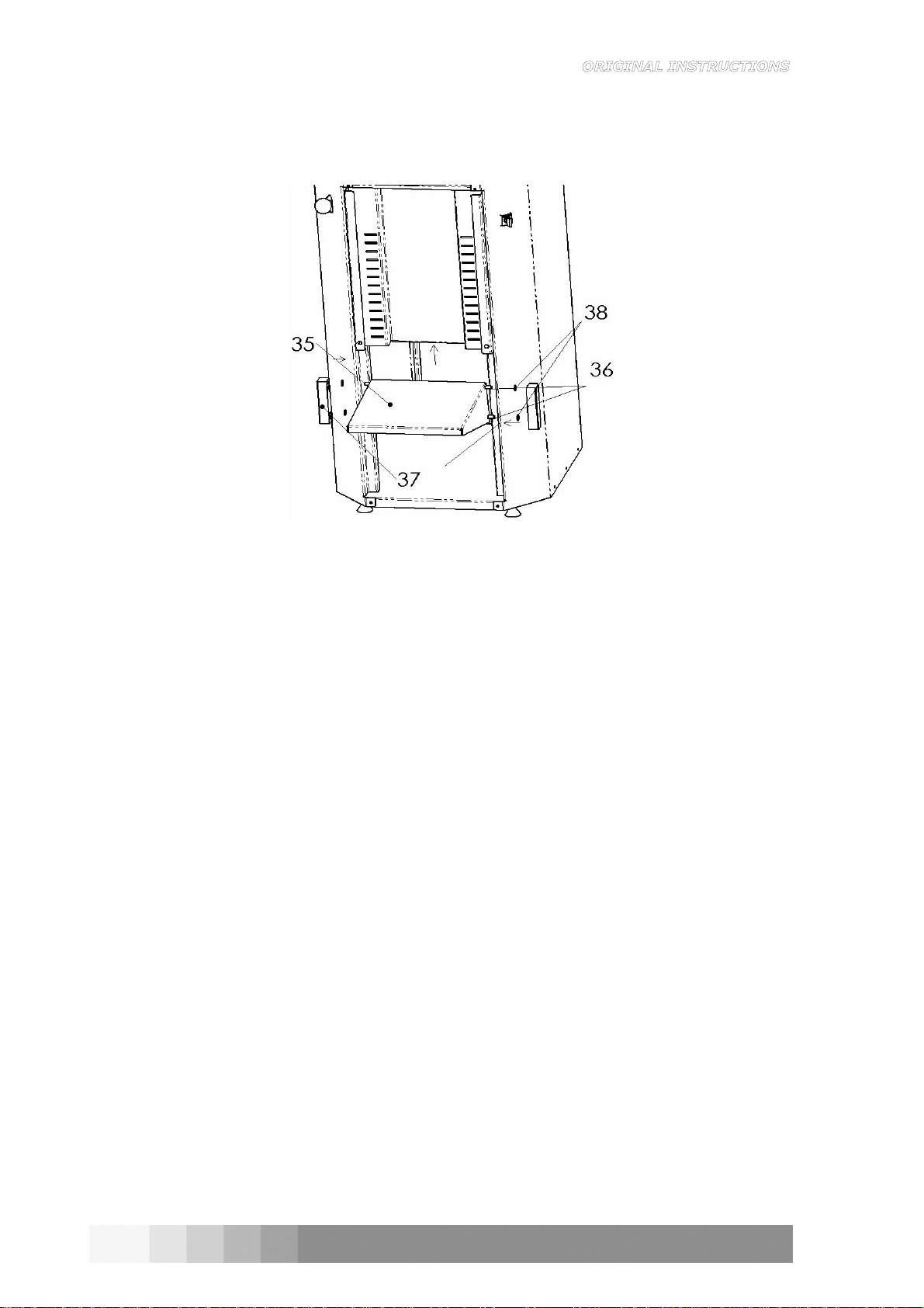
2) Insert the Can shelf Pivot Bars (36) x 2 through the holes in the Can shelf (35) (Figure 3-4).
3) Place a Nylon Washer (38) on each end of the two Can shelf Pivot Bars as required.
4) Fit the Nylon Block onto the assembly (37) (Figure 3-4), locating the Pivot Bar in the holes in
the Nylon Block.
5) Holding the assembly together, slide the Nylon Blocks into the slots (Figure 3-4). Once the
Nylon Blocks are fully inside the slots in the Front Panel, the assembly will be held together,
simply raise the shelf until it locks in one of the notches in the Front Panel.
6) Re-insert the two M4 x 12 Sems screws in the lower of the Front Panel using a Philips
screwdriver, which were removed in step 1 above, so that the shelf can not fall out.
ITEM DESCRIPTION QTY.
35 CAN SHELF 1
36 CAN SHELF PIVOT BAR 2
37 NYLON SLIDE BLOCK 2
38 NYLON WASHER 4
10
COROB™ D50
Figure 3-4
11
4PRIMING THE MACHINE
With the unit assembled and canisters mounted, the following steps should be carried out to
ensure that your machine is properly prepared for accurate and trouble-free dispensing.
The canisters have a capacity of 3.17 Quarts and it is recommended that only one quart of
colorant be used on the initial filling. Additional colorant can be added once proper operation is
achieved.
Figure 4-1 Figure 4-2 Figure 4-3
1) Place each can of colorant into a mixer or shaker for approximately 5 minutes (or as specified
by the colorant manufacturer) to mix any settled pigment.
2) Remove canister lids.
3) Pour the contents of each can of colorant into individual canisters.
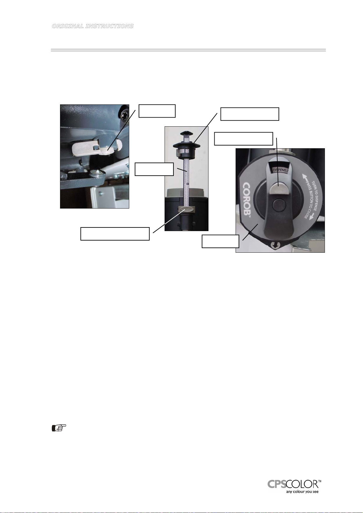
4) Set the gauge (Ref. # 2) of each pump to the 3Y or 100 ml setting, by depressing the spring
loaded button (Ref. # 3) and lifting the gauge by its handle.
5) Prime each cylinder by lifting up the plunger handle (Ref. # 1) to its maximum travel, and
pressing the plunger handle downward fully, WITHOUT OPENING THE VALVE HANDLE!
Repeat this process 5-6 times: this draws colorant from the canister into the cylinder and
purges the air from the system.
6) Lift the plunger handle to its maximum travel. Place a clean can or paper cup under the
dispense nozzle (Ref. # 5). Open the discharge valve by turning the valve Handle (Ref. # 4)
in a clockwise direction until it locks into place. Push the plunger handle down fully to
dispense colorant into the cup. Return the valve Handle to the closed position by pressing the
release button (Ref. # 6). Repeat this procedure until the colorant emerges as an unbroken
stream.
7) Once the cylinder is free of air, repeat steps 4 and 5 for all remaining canisters. Return all
dispensed colorant to its respective canisters. Your machine is now ready for use!
Do not add colorant when agitation is taking place.
Nozzle # 5
Handle # 4
Plunger Handle # 1
Gauge # 2
Gauge Lock Button # 3
Release Button # 6

12
COROB™ D50
5TINTING INSTRUCTIONS
5.1 Dispensing from the cylinder
1) With the plunger set at the required measurement and the cylinder full, turn the spring
loaded valve handle (Ref. # 2) clockwise until it locks into position.
2) Push the plunger handle (Ref. # 1) down completely, in a smooth even motion.
3) Your full dispense is now complete.
4) Return the valve handle to the closed position by pressing the release button (Ref. # 3).
5) Repeat the charging and discharging process for the required strokes (total formula).
Continue with the next required colour.
6) When the entire paint order is complete, gently lower gauges to zero position.
DO NOT push gauge release button and allow gauges to drop down.
Lower manually to avoid damage.
Handle # 2 Dispense Position
Handle # 2 Closed Position
Figure 5-1 Figure 5-2 Figure 5-3
5.2 Automatic drip control piston
Activation of the Automatic Drip Control Piston provides a small suction of air to clean the
dispense nozzle of any remaining colorant and ensures clean dispensing ports and greater
accuracy. The valve automatically works on each dispense.
5.3 Tinting instructions
1) Identify the colour you wish to supply, either by name or code number.
2) Refer to your color formula reference book for the tint formula and note the tint base
required.
3) Determine the formula required for the size of paint can being tinted.
Plunger Handle # 1

13
4) Ensure all gauges are set to zero before beginning.
5) Place the open can of paint under the dispensing nozzle. Unlock the Carousel Index Lever and
rotate the turntable until the appropriate canister is directly over the can of paint, and lock
the Carousel Index Lever. If a formula which cannot be measured in one dispense is required,
multiple dispenses will be necessary. It is always best to divide a formula into equal
dispenses.
6) Set the Gauge by pressing the Gauge Locking Button (Ref. # 3) and raising the Gauge until
the desired measurement appears beneath the arrow in the window at the top of the Plunger
Handle (Ref. #1).
7) To add smaller increments than the main gauge allows, turn the Smart Gauge handle located
on the piston handle in a clockwise direction, until the desired increment appears in line with
the arrow in the window.
8) With the gauge correctly set, slowly and gently lift the plunger handle until it reaches the
gauge handle. Continue to hold for a few seconds to ensure that the cylinder has completely
filled with colorant.
It is always best to divide the required formula into equal dispenses, even if it requires more
dispenses than what might otherwise be required. Mis-tints are generally caused by operator error
in setting the gauges. The fewer changes in the gauge settings, the lower the chances of errors.
9) Turn the handle 90 degrees clockwise to the dispense position until it locks into position. En-
sure a can is in position under the nozzle.
10) Press the plunger handle down to dispense the colorant. Ensure the plunger handle is
pressed down fully.
11) Press the button on the handle firmly and the handle should automatically rotate 90 degrees
anticlockwise and return to the close position.
Figure 5-4
DO NOT open or operate the dispensing Valve Handle while charging the cylinder.
If the valve handle is opened, even the slightest amount, air will be drawn into the cylinder
chamber resulting in an inaccurate dispense. If the valve handle is accidentally opened during
CHARGING, close valve and press the plunger handle down to return the colorant to the canister.
If the colorant level is low in the canister, air can also be sucked into the cylinder.
Press the plunger handle down to return the colorant to the canister. Add 1 or 2 quarts of new
colorant. The cylinder must be re-primed. Refer to the instructions on chapter 4.
Plunger Handle # 1
Gauge # 2
14
COROB™ D50
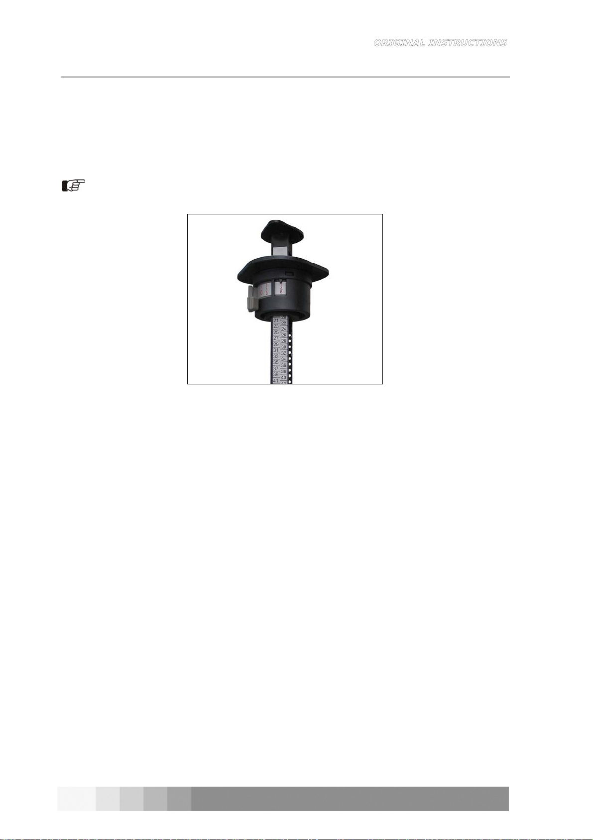
5.4 Smart Gauge
The Smart Gauge (Figure 5-5) is an innovative way of dispensing increments smaller than 1 part.
The Smart Gauge allows you to dispense in 1/8 part increments.
For formulas specifying dispenses for example a 1/2 part, rotate the Smart Gauge knob until the
1/2 number is aligned with the pointer.
The Smart Gauge settings can be used in combination with a regular setting, thereby making
complete dispenses possible with a single discharge.
IMPORTANT: ALWAYS return the Smart Gauge knob to the “0” position after completing a
dispense.
Figure 5-5

15
6MAINTENANCE
6.1 Daily Maintenance
Keeping the Nozzle and Tip Seal clean and free
of dried, dripping or collecting colorant is
essential for trouble-free dispensing.
It is recommended the Nozzle and Seal Tip be
cleaned daily with a moist cloth: water or
mineral spirits is satisfactory.
Figure 6-1
DO NOT use lacquer thinner (MEK). Cleaning the colorant from the nozzle seal pad will
lessen the possibility of mis-tints caused by the collection of colorant. Large accumulations
of colorant on the seal arm/pad may be caused by a malfunction of the automatic drip
control piston.
6.2 Periodic Maintenance
When the machine is not being used on a regular daily base, the following procedures
should be carried out.
1) Check the level of colorant and top up if required.
2) Open and close each Valve Handle five times.
3) Set gauge to the maximum 3Y and stroke the plunger handle up and down three times
without opening the Valve Handle.
4) Check Valve Handle and nozzle Seal Arms/Tips for possible damage, and clean thoroughly.
5) Dispense colorant into a paper cup and return to canister. Constant movement of colorant is
required to prevent hardening of colorant in nozzle and valve assembly.
Colorants are heavy bodied fluids containing particle of pigment. During the plunger operation, a
slight amount of colorant may stick to the cylinder wall, which after a period of time, may cause
drag or stiffness in the operation of the plunger. A small amount of stiffness should cause no
concern. If the stiffness of operation becomes difficult, complete replacement of pump will be
required.
Nozzle
Tip seal

16
COROB™ D50
6.2.1 Lubricating the piston
1) Press the gauge release bar.
2) Lift gauge up until it is out of the end cap housing.
3) Add 2 cl of Castor oil into the gauge slot.
4) Insert the gauge back into the end cap housing.
Take care not to damage the gauge bar decal.
5) Set the gauge to 3Y and move the piston up and
down fully 5 times.
Figure 6-2
17
7TROUBLESHOOTING
PROBLEM CAUSE SOLUTION
Intermittent spurts of colorant
from the nozzle during dispensing. Low colorant level, allowing air
into the pump cylinder.
Pump not properly primed.
Fill canister and operate the
plunger several times, without
opening the valve handle.
Dispense colorant into a paper cup
to remove the air.
Prime pump (chapter 4).
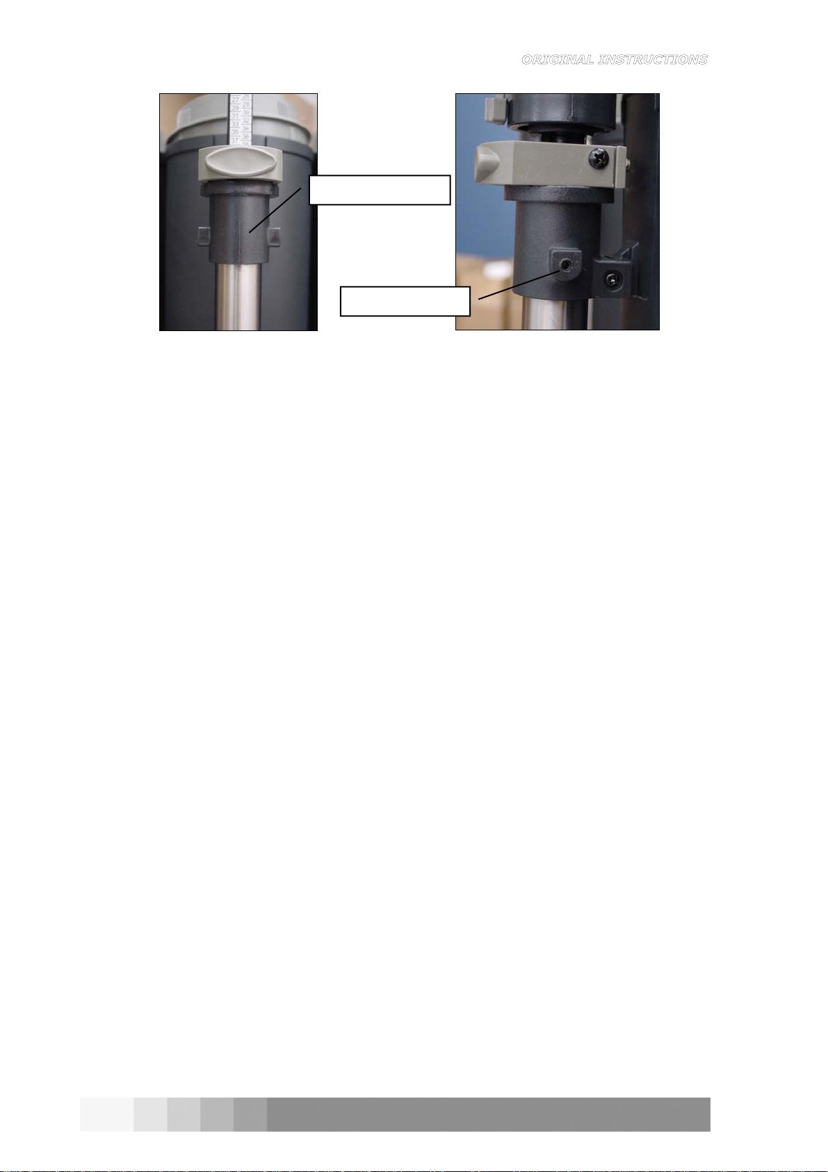
End cap twists or lifts during
operation. End cap loose on cylinder. Push down end cap (Ref. # 9)
onto the cylinder, and lightly
tighten the two setscrews (Ref. #
11) in the end cap, until it can no
longer be twisted by hand.
Canister is loose on turntable. Tighten the mounting screws
(chapter 3.3).
Colorant appears on the piston
shaft, and or gauge. Worn or loose piston seals. Replace Piston Tube Assembly.
Contact your Supplier.
Colorant does not dispense easily. Nozzle is clogged or too small.
Colorant is too heavy. Clear nozzle of obstructions. If
problem continues, use a larger
nozzle. Thoroughly clean out
canister and refill with new
colorant.
Pump tube is loose on the
canister. Pump Nut is loose. Tighten the Pump Nut found at the
base of the Pump connecting the
Pump to the Valve Housing. Also
ensure grub screws are tight in
the End Cap Housing.
Colorant leaks around the outlet
nozzle. Nozzle O-Ring is lost or damaged. Replace Nozzle.
Colorant leaks around from the
back of the Valve Handle. Damaged or worn O-Ring. Replace Canister Assembly.
Gauge line does not line up with
plunger handle. Loose plunger handle. Tighten plunger handle and re-
calibrate (chapter 10).
Plunger handle stiff. Dry Piston Tube. Lubricate the piston with castor
oil. Lift gauge out of the slot in the
end cap housing and apply 2cl of
castor oil through the slot, into the
top of the piston tube.
18
COROB™ D50
Figure 7-1 Figure 7-2
End Cap Housing # 9
Grub Screws # 11
Table of contents
Other CPS COLOR Dispenser manuals


