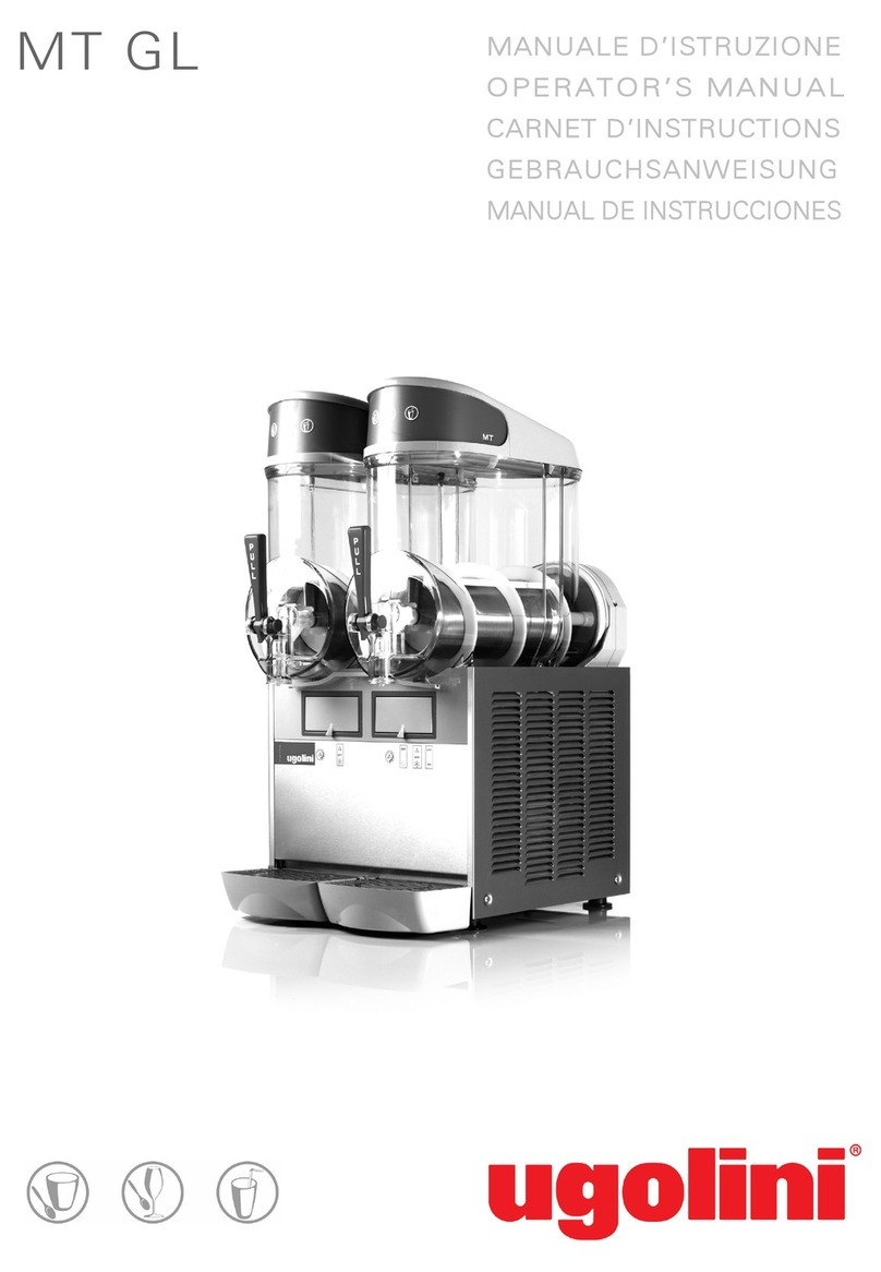
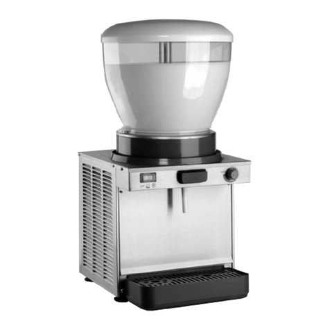
Ugolini Quick-GEL User manual

MANUALE D’ISTRUZIONE
OPERATOR’S MANUAL
CARNET D’INSTRUCTIONS
GEBRAUCHSANWEISUNG
MANUAL DE INSTRUCCIONES

2
DICHIARAZIONE DI CONFORMITÀ CE
Noi Ugolini spa, via dei Pioppi, 33 20090 Opera Milano ITALY dichiariamo, sotto la nostra responsabilità, che l’apparecchio DISTRIBUTORE DI
BEVANDE FREDDE - Marca: UGOLINI S.p.A. - Fabbricante: UGOLINI S.p.A. - Modelli: Quick-GEL - 230V 50Hz sono conformi alle seguenti
Normative:
In ottemperanza alle Direttive 2014/30/CE, 2014/35/CE.
EC DECLARATION OF CONFORMITY
We Ugolini spa, via dei Pioppi, 33 20090 Opera Milano ITALY declare, under our responsibility, that the apparatus COLD DRINK DISPENSER -
Trademark: UGOLINI S.p.A. - Manufacturer: UGOLINI S.p.A. - Model: Quick-GEL - 230V 50Hz are in conformity with the following Standards:
Following the provisions of the Directives 2014/30/CE, 2014/35/CE.
DECLARATION DE CONFORMITE CE
Nous Ugolini spa, via dei Pioppi, 33 20090 Opera Milano ITALY déclarons, sous notre responsabilité, que les appareil DISTRIBUTEUR REFROI-
DISSEUR DE BOISSONS - Marque: UGOLINI S.p.A. - Constructeur: UGOLINI S.p.A. - Modèle: Quick-GEL - 230V 50Hz sont conformes aux Normes
suivantes:
Conformément aux Directives 2014/30/CE, 2014/35/CE.
EG-ÜBEREINSTIMMUNGSERKLÄRUNG
Wir Ugolini spa, via dei Pioppi, 33 20090 Opera Milano ITALY erklären auf eigene Verantwortung, daß die Gerät KALTGETRÄNKE DISPENSER -
Marke: UGOLINI S.p.A. - Hersteller: UGOLINI S.p.A. - Modell : Quick-GEL - 230V 50Hz mit den folgenden Normen übereinstimmen:
Gemäß den EWG-Richtlinien 2014/30/CE, 2014/35/CE.
DECLARACIÓN DE CONFORMIDAD CE
Nosotros Ugolini spa, via dei Pioppi, 33 20090 Opera Milano ITALY declararamos, bajo nuestra responsabilidad, que los aparato DISTRIBUIDOR
DE BEBIDAS FRIAS - Marca: UGOLINI S.p.A. - Fabricante: UGOLINI S.p.A. - Modelo: Quick-GEL - 230V 50Hz responden con las siguientes
Normativas:
En cumplimiento de las Normas 2014/30/CE, 2014/35/CE.
-
-
-
EN60335-1 (2012)+A11(2014)
EN60335-2-24 (2010)
EN60335-2-75 (2004) + A1 (2005) + A11 (2006) + A2 (2008) + A12 (2010)
-
-
-
EN 55014 -1 (2006) + A1 (2009) + A2 (2011);
EN 55014-2 (2014) + A1 (2001) + A2 (2008)
EN 61000-3-2 (2014); EN61000-3-3 (2013)
-
-
-
EN60335-1 (2012)+A11(2014)
EN60335-2-24 (2010)
EN60335-2-75 (2004) + A1 (2005) + A11 (2006) + A2 (2008) + A12 (2010)
-
-
-
EN 55014 -1 (2006) + A1 (2009) + A2 (2011);
EN 55014-2 (2014) + A1 (2001) + A2 (2008)
EN 61000-3-2 (2014); EN61000-3-3 (2013)
-
-
-
EN60335-1 (2012)+A11(2014)
EN60335-2-24 (2010)
EN60335-2-75 (2004) + A1 (2005) + A11 (2006) + A2 (2008) + A12 (2010)
-
-
-
EN 55014 -1 (2006) + A1 (2009) + A2 (2011);
EN 55014-2 (2014) + A1 (2001) + A2 (2008)
EN 61000-3-2 (2014); EN61000-3-3 (2013)
-
-
-
EN60335-1 (2012)+A11(2014)
EN60335-2-24 (2010)
EN60335-2-75 (2004) + A1 (2005) + A11 (2006) + A2 (2008) + A12 (2010)
-
-
-
EN 55014 -1 (2006) + A1 (2009) + A2 (2011);
EN 55014-2 (2014) + A1 (2001) + A2 (2008)
EN 61000-3-2 (2014); EN61000-3-3 (2013)
-
-
-
EN60335-1 (2012)+A11(2014)
EN60335-2-24 (2010)
EN60335-2-75 (2004) + A1 (2005) + A11 (2006) + A2 (2008) + A12 (2010)
-
-
-
EN 55014 -1 (2006) + A1 (2009) + A2 (2011);
EN 55014-2 (2014) + A1 (2001) + A2 (2008)
EN 61000-3-2 (2014); EN61000-3-3 (2013)
vedere targa dati sulla macchina
see data plate on the machine
voir la plaque sur l’appareil
siehe Dispenser Typenschild
ver la placa del distribuidor
Ugolini spa
L’Amministratore Delegato
(luogo ed anno di prod. - place and mfr. year - lieu et an de production
Produktionsort und Produktionsjahr - lugar y año de producción)

3
Questo apparecchio è coperto da uno o più dei seguenti brevetti e/o altre domande di brevetto depositate:
This dispenser is manufactured under one or more of the following U.S.patents and/or other pending patents:
Cet appareil est couvert par un ou plusieurs des brevets suivants et/ou autres demandes de brevet déposées:
Dieses Gerät ist durch eines oder mehrere der folgenden Patente und/oder andere eingetragene Patentanmeldungen geschützt:
Este aparato está cubierto por una o varias de las siguientes patentes y/o otras solicitudes de patente ya registradas:
US D760,305 - US 2013,0263747 - US 2013,0152620 - US 2013,0098098 - US 2012,0234035 - US 6467,944 - US 5713,214 - US 6546,843 - DE 6010,0684
WO 2012,085692 - WO 2012,032425 - WO 2012,004687 - WO 2013,011078 - EP 2478,774 - EP 1155,622 - EP 0799,575 - EP 1162,168
4
14
23
33
42
1. L'apparecchio è garantito per un periodo di dodici mesi dalla data di acquisto.
Tale data viene certificata dalla ricevuta e/o fattura fiscale e/o da un documento at-
testante l'avvenuta consegna dell'apparecchio all'acquirente.
2. Per garanzia si intende la sostituzione o riparazione gratuita delle parti compo-
nenti l'apparecchio riconosciute difettose all'origine, per vizi di fabbricazione a con-
dizione che: A- il difetto di funzionamento dell'apparecchio sia stato -a pena di
decadenza- denunziato per iscritto dall'acquirente al produttore entro otto giorni dal-
la scoperta del difetto stesso; B-ove l'acquirente abbia diritto alla garanzia, sarà do-
vere di Ugolini s.p.a. provvedere -a sua insindacabile discrezione- alla sostituzione
integrale dell'apparecchio, ovvero alla sostituzione o riparazione delle sole parti di
esso riconosciute difettose all'origine, per vizi di fabbricazione.
3. Sono escluse dalla garanzia le parti dell'apparecchio aventi funzione estetica e/o
ornamentale, nonché le parti che dovessero risultare difettose a causa -o per effet-
to- di circostanze non connesse a vizi di fabbricazione ovvero a negligenza, imperi-
zia o trascuratezza nell'uso, installazione errata o, comunque, difforme rispetto le
istruzioni fornite dal produttore, manutenzione errata o eseguita da personale non
autorizzato da Ugolini s.p.a., o, comunque, effettuata in modo difforme rispetto alle
istruzioni fornite dal produttore, (ivi) trasporto eseguito in modo inidoneo o, comun-
que, con modalità differenti rispetto quelle indicate dal produttore; sono altresì
esclusi dalle prestazioni in garanzia gli interventi tecnici inerenti l'installazione e l'al-
lacciamento agli impianti di alimentazione elettrica o idrica.
4. E' esclusa dalla garanzia la responsabilità del produttore per l'ipotesi in cui l'ap-
parecchio determini la distruzione o il deterioramento di una cosa diversa dall'appa-
recchio stesso; è, inoltre, esclusa la responsabilità del produttore per eventuali
danni che possano, direttamente o indirettamente, derivare a persone e/o cose per
effetto della -e/o in correlazione alla- mancata o inesatta osservanza di tutte le pre-
scrizioni indicate nel manuale di istruzioni allegato all'apparecchio; nelle ipotesi in
cui il produttore sia tenuto a rispondere dei danni subiti dall'acquirente, il risarcimen-
to non potrà in ogni caso comportare, a carico di Ugolini s.p.a., un esborso superiore
al prezzo versato dall'acquirente per l'acquisto del prodotto.
5. Sono escluse dalla garanzia anche tutte le spese di trasporto.
6. L'intervento di riparazione dell'apparecchio deve essere effettuato presso Ugolini
s.p.a., ovvero presso uno dei laboratori autorizzati dalla medesima; le spese di tra-
sporto, ed i rischi ad esso connessi, sono interamente a carico dell'acquirente; ove
l'intervento di riparazione sia effettuato a domicilio, l'acquirente sarà tenuto a corri-
spondere il diritto fisso di chiamata in vigore presso il produttore alla data dell'inter-
vento.
7. Trascorsi dodici mesi dall'acquisto, decade il diritto di garanzia e l'assistenza ver-
rà esplicata addebitando, oltre alle spese di manodopera, anche il costo delle parti
sostituite e quelle di trasporto.
8. Sono esclusi la sostituzione dell'apparecchio ed il prolungamento della garanzia
a seguito di intervenuto guasto.
9. E' escluso dalla garanzia l'apparecchio la cui targa di identificazione risulti mano-
messa, asportata o comunque in condizioni tali da non rendere possibile l'identifica-
zione certa dell'apparecchio stesso.
10. Tale garanzia è valida solo nel territorio in cui l'acquirente ha la propria sede le-
gale alla data dell'acquisto dell'apparecchio.
GARANZIA
Ai sensi dell’art.13 del Decreto Legislativo 25 Luglio 2005, n.151 “Attuazione delle Direttive
2002/95/CE, 2002/96/CE e 2003/108/CE, relative alla riduzione dell’uso di sostanze perico-
lose nelle apparecchiature elettriche ed elettroniche, nonchè allo smaltimento dei rifiuti”.
Il simbolo del cassonetto barrato riportato sull’apparecchiatura o sulla sua confezione indica
che il prodotto alla fine della propria vita utile deve essere raccolto separatamente dagli altri
rifiuti.
La raccolta differenziata della presente apparecchiatura giunta a fine vita è organizzata e gestita dal
produttore. L’utente che vorrà disfarsi della presente apparecchiatura dovrà quindi contattare il pro-
duttore e seguire il sistema che questo ha adottato per consentire la raccolta separata dell’apparec-
chiatura giunta a fine vita.
L’adeguata raccolta differenziata per l’avvio successivo dell’apparecchiatura dismessa al riciclaggio,
al trattamento e allo smaltimento ambientalmente compatibile contribuisce ad evitare possibili effetti
negativi sull’ambiente e sulla salute e favorisce il reimpiego e/o riciclo dei materiali di cui è composta
l’apparecchiatura.
Lo smaltimento abusivo del prodotto da parte del detentore comporta l’applicazione delle sanzioni am-
ministrative previste dalla normativa vigente.
Pursuant to the European Directives 2002/95/EC, 2002/96/EC and 2003/108/EC, on restri-
cting the use of hazardous substances in electric and electronic equipment and on the di-
sposal of waste material.
The crossed out wheelie bin symbol applied to equipment or packaging means that the pro-
duct should be collected separately from other types of waste at the end of its useful life.
The separate collection of equipment that has reached the end of its life cycle is organised
and managed by the manufacturer. A user that wishes to dispose of this product should therefore con-
tact the manufacturer and follow the instructions given with respect to the separate collection of obso-
lete equipment.
Correct separate collection and the subsequent recycling, treatment and environmentally compatible
disposal of discarded equipment is of aid in avoiding possible negative effects for the environment and
people's health and facilitates the re-use or recycling of the materials of which the equipment is made.
Illegal disposal of this product on part of the owner will give way to the application of administrative
fines as provided by current laws.
Conformément aux Directives européennes 2002/95/CE, 2002/96/CE et 2003/108/CE, rela-
tives à la réduction de l'utilisation de substances dangereuses dans les appareils électriques
et électroniques, ainsi qu'à l'élimination conforme et au recyclage des déchets.
Le symbole de la poubelle barrée indiqué sur l'appareil ou sur sa boîte indique qu'à la fin de
sa vie utile ce produit doit être éliminé séparément des autres déchets et conformément aux
lois en vigueur en la matière.
La collecte différenciée de cet appareil à la fin de sa vie utile, est organisée et gérée par le
producteur. Par conséquent, lorsque l'utilisateur souhaitera jeter cet appareil il devra contacter le pro-
ducteur et respecter le système que ce dernier aura mis en place pour réaliser la collecte différenciée
des appareils arrivés à la fin de leur vie utile.
La collecte différenciée correctement effectuée, suivie de l'envoi des appareils éliminés au recyclage,
avec traitement et élimination des déchets dans le plus strict respect de l'environnement, est une
procédure fondamentale qui contribue à éviter les possibles effets négatifs sur notre environnement
et sur notre santé, et qui favorise la réutilisation et/ou le recyclage des matériaux qui composent ces
appareils.
L'élimination abusive de ce produit par son propriétaire comporte l'application de sanctions administra-
tives sévères, prévues par la réglementation en vigueur.
Laut EG-Richtlinien 2002/95/EG, 2002/96/EG und 2003/108/EG zur Beschränkung der
Verwendung gefährlicher Stoffe in elektronischen Geräten sowie zur Abfallentsorgung.
Das Symbol des durchgestrichenen Abfallcontainers auf der Packung gibt an, dass das Pro-
dukt zum Ende seiner Lebensdauer getrennt von den anderen Abfällen entsorgt werden
muss.
Die getrennte Abfallsammlung dieses Geräts am Ende seiner Lebensdauer wird vom Her-
steller organisiert und verwaltet. Der Nutzer, der das Gerät entsorgen möchte, muss sich daher mit
dem Hersteller in Verbindung setzen und das System befolgen, das dieser angewendet hat, um das
Altgerät der getrennten Abfallsammlung zuzuführen.
Eine angemessene Mülltrennung, die das Altgerät zur Wiederverwertung und umweltverträglichen En-
tsorgung führt, trägt dazu bei, mögliche negative Auswirkungen auf die Umwelt und die Gesundheit zu
vermeiden und fördert die Wiederverwendung bzw. das Recycling der Materialien, aus denen das
Gerät besteht.
Die unerlaubte Entsorgung des Produkts durch den Benutzer zieht die Anwendung der von der gel-
tenden Richtlinie vorgesehenen Ordnungsstrafen nach sich.
En virtud de las Directivas europeas 2002/95/CE, 2002/96/CE y 2003/108/ CE, relativas a
la reducción del uso de sustancias peligrosas en los aparatos eléctricos y electrónicos, así
como a la eliminación de residuos.
El símbolo del contenedor tachado que aparece impreso sobre el aparato o sobre su emba-
laje indica que al finalizar la vida útil del producto éste nunca debe depositarse junto al resto
de residuos.
La recogida selectiva de este equipo cuando llegue al final de su vida útil la gestionará y organizará
el fabricante. El usuario que desee deshacerse de este equipo deberá ponerse en contacto con el fa-
bricante y seguir el sistema que éste haya adoptado para permitir la recogida selectiva del aparato
que haya llegado al final de su vida útil.
La recogida selectiva adecuada para el posterior reciclaje, tratamiento y eliminación del equipo inser-
vible, compatible con el medio ambiente, contribuye a evitar posibles efectos negativos para el medio
ambiente y para la salud y favorece la reutilización y/o el reciclaje de los materiales de los que está
compuesto el equipo.
La eliminación inadecuada del producto por parte de su propietario comportará la aplicación de las
sanciones administrativas previstas por la normativa vigente.
ELENCO RICAMBI
-
Disponibile in internet all’indirizzo :
http://www.ugolinispa.com/download
SPARE PARTS LIST
- Available on the Internet at :
http://www.ugolinispa.com/download
LISTE DES PIECES DE RECHANGE
-
Sur le site Internet à l'adresse :
http://www.ugolinispa.com/download
ERSATZTEILLISTE
-
Auf der Internet-Seite :
http://www.ugolinispa.com/download
DESCRIPCION PIEZAS DE REPUESTO
-
En el sitio de Internet en :
http://www.ugolinispa.com/download
14
1 ELECTRICAL SAFETY INSTRUCTIONS
1Before connecting the dispenser to the mains, check that
the voltage shown on the rating plate matches your electricity
supply. Connect the dispenser to a single-phase supply
through an earthed socket as required by current regulations. If
the dispenser is to be disconnected from the power supply
using a single pole switch, the gap between the contacts on this
switch must be sufficiently wide to guarantee full disconnection
under category III overload conditions.?
2Do not use extension cables to connect the appliance.
3To avoid any risks, if the power cable is damaged, it must
be replaced by the manufacturer, by an authorised technician
or by a similarly qualified person.
4The dispenser is not suitable for outdoor use.
5The dispenser must be installed in the upright position.
6Before cleaning, always disconnect the dispenser by
removing the plug from the socket.
7Always disconnect the dispenser before removing any of
the panels for cleaning or maintenance work.
8Do not use a water jet to clean the dispenser.
9This appliance must not be operated by children.
10 Do not let children play with the appliance.
11 This appliance must not be used by persons with reduced
physical, sensory or mental capabilities or with a lack of
experience and knowledge unless they have supervision or
have been trained regarding the safe use of the appliance and
understand the risks involved.
12 Only persons who know and have practical experience of
the appliance are permitted access to the inner components of
the dispenser, especially when dealing with issues regarding
safety and hygiene.
2 HYGIENIC SAFETY INSTRUCTIONS
1This appliance is intended exclusively for domestic and
similar use.
2For the appliance to operate correctly, room temperature
must be between +5° and +32°C.
3Use the appliance to cool the indicated liquids only.
4Do not introduce dangerous or toxic liquids to the appliance.
3 TECHNICAL CHARACTERISTICS
The manufacturer reserves the right to amend this manual
without notice.
4 INTRODUCTION
Read this instruction manual carefully to find out all the
characteristics of the dispenser.
As with all mechanical products, this dispenser also requires
cleaning and care. In addition, its correct operation may be
compromised by possible errors made by the operator during
the disassembly and cleaning operations. For this reason, it is
important that the disassembly, cleaning, sanitising and
reassembly procedures - being everyday tasks - are familiar,
without any room for error on the part of the dispenser user.
5 INSTALLATION
1Take the dispenser out of its packaging, which we
recommend you keep for future requirements.
2Make sure that the dispenser has not been damaged during
transportation. If this is the case, immediately make a claim
with your carrier.
3Place the dispenser onto a counter designed to withstand
its weight, including when full.
4Leave a clearance of at least 15 cm around the whole
dispenser to avoid obstructing the cooling air flow.
5Check the stability of the appliance and adjust the height of
the feet if necessary. Should the dispenser be supplied with a
series of high feet (100 mm approx.), replace the originals with
Bowl capacity, approx l 4
Evaporator capacity, approx l 2
Dimensions:
width cm 26
depth cm 57
height cm 72
Net weight, approx. kg 50
Gross weight, approx. kg 55
Hermetic compressor
Air-cooled condenser
Overload protector
Noise level lower than 70 dB (A)
IMPORTANT
Electrical characteristics: read the data featured on the
data plate of each dispenser; this data plate is situated in
the lower part of the front panel, behind the drip tray. The
serial numbers of appliances (preceded by the symbol #)
are indicated on the frame, at the rear of the appliance,
behind the condenser cover panel. The data specified on
the data plate are always those you should refer to.
Quick-GEL

15
these.
6The dispenser is not supplied pre-cleaned and sanitised by
the factory. Before use, it must be disassembled, cleaned and
sanitised according to the instructions provided herein in
chapter 7.4 CLEANING.
6 TO OPERATE SAFELY
1Do not use the dispenser before reading this instruction
manual first.
2Do not use the dispenser unless it is earthed correctly.
3Do not operate the dispenser if the panels are not in place
and secured with screws.
4Do not insert your fingers or objects into the panel slits or in
the tap orifice.
5Do not remove parts or panels for cleaning or maintenance
without first making sure the dispenser is disconnected from
the electricity supply.
6The cover must remain closed at all times.
7 OPERATING PROCEDURES
figure 1
This appliance is equipped with an upper tank designed to keep
the ice-cream preparation base refrigerated and a lower cylinder
for the production of the ice cream.
Every time a portion of ice cream is dispensed, the same
quantity of ice cream mixture drops down by the force of gravity
from the upper tank into the lower cylinder.
In order to obtain softer and lighter ice cream, make sure that a
certain quantity of air enters the cylinder together with the
mixture. To this end, the machine is equipped with a purpose-
designed two-part mixing pipe. (see figure 2)
figure 2
For best results, the following steps must be performed in the
order specified:
1Insert the lower part of the mixing pipe into the purpose-
provided connection slot between the tank and the cylinder,
making sure you direct it in such a way as to insert it fully in its
seat. (see figure 3)
figure 3
2Pour the mixture into the upper tank and wait for the
cylinder to fill up. This will occur when no more air bubbles exit
the holes in the mixing pipe. (see figure 4)
figure 4
ATTENTION
Make sure the appliance is earthed correctly; if this is not
the case, this may cause electric shocks to people or
damage to the dispenser.
IMPORTANT
Position the appliance in such a way that the power sup-
ply cable plug is easily accessible.
IMPORTANT
Before use, clean and sanitise the dispenser according
to the instructions provided herein in chapter 7.4.2 CLE-
ANING.
IMPORTANT
If the tap assembly has not been installed, the appliance
cannot operate and the display shows the tap assembly
open icon (see figure 1).

16
3Insert the upper part of the mixing pipe into the lower one.
(see figure 5)
figure 5
4Turn the upper part of the mixing pipe completely clockwise
in order to stop the mixture entering the cylinder. (see figure 6)
figure 6
5Close the upper cover, turn on the machine and start
preparing ice cream. (See 7.1 DESCRIPTION OF
CONTROLS)
6When the ice cream is ready, open the cover and turn the
upper part of the mixing pipe anti-clockwise to allow the mixture
to enter the lower cylinder.(see figure 7)
The quantity of air in the ice cream can be adjusted, keeping in
mind that, starting from the closing position:
figure 7
7Close the upper cover again.
8Dispense the ice cream using the faucet handle.
9In case the density setting range wouldn’t be enough to
obtain the required result, the mix can be modified as follows:
Ice cream too soft : increase the quantity of liquid (water or
milk) from 5 % to 10 % of the total volume.
Ice cream too hard (oppure too compact) : decrease the
quantity of liquid (water or milk) from 5 % to 10 % of the total
volume.
10 The dispenser must operate continuously: the cooling
system will stop automatically when the product is ready to be
dispensed. The mixing device will decrease its speed and only
increase it at the time of dispensing. At default time intervals,
the cooling system will start up again and the mixing device will
increase its speed in order to restore the proper density to the
product.
7. 1 DESCRIPTION OF CONTROLS
The dispenser is fitted with a main switch, an on/off key and a
touch display. The following operating modes are available:
ICE CREAM PRODUCTION: in this operating mode, the
dispenser prepares ice cream.
CONSERVATION: in this operating mode, the dispenser keeps
the liquid mixture at a suitable temperature to preserve it. This
function is useful at night to keep the quality of the mixture intact
and limit electricity consumption.
WASHING: in this operating mode, cooling is disabled. This
function is useful during machine washing and sanitising to
prevent the solution used from being cooled and freezing.
MAIN SWITCH
The main switch is located on the top distributor in the backside
part.
Its function is as follows:
ON/OFF KEY
The ON/OFF key P is situated to the right of the touch display.
If indicator light Q comes on, this means the dispenser is
switched on and in stand-by mode, ready for operation. Hold
down key P for one second to switch the dispenser on and off.
complete rotation
anti-clockwise :fully open, lower quantity of air
in the ice cream
minimum rotation anti-
clockwise :only open slightly, greater quan-
tity of air in the ice cream
IMPORTANT
Use the dispenser with foodstuff only.
Position 0 :dispenser switched off
Position I :dispenser enabled for operation but in Stand-by
mode. Only indicator light Q is on.
IMPORTANT
If you turn the dispenser off and back on at the main swi-
tch, it will restart in the same operating mode it was in
when it was switched off.

17
TOUCH DISPLAY
figure 8
The following icons appear on the display:
FOR DISPENSER OPERATION
Set the main switch to position I. Red indicator light Q comes on.
Hold down key P until the dispenser starts up again.
Select the desired function using icons A, B, c or D.
ICE CREAM MODE
In this operating mode, the machine produces ice cream and the
mixture in the upper tank is kept at a suitable temperature to
preserve it. The ice cream preparation status is indicated on the
display by the central icon and by the colour of the arrows.(see
figure 9)
figure 9
When the ice cream is ready, the mixing system slows down, the
cooling system stops and the appliance switches to awaiting to
dispense mode. At default intervals (factory set to every 10
minutes), the mixing system increases the speed and the
cooling system is started to restore the proper ice cream
density.
When the dispensing tap is opened, the mixing system
increases its speed and the cooling system is enabled.
In order to produce ice cream, the upper tank must contain a
suitable quantity of mixture. If this is not the case, the cooling
system is not started and the display indicates the icon for low
product.(see figure 10)
figure 10
Density adjustment
The density of the ice cream can be adjusted on a scale of 1 to
10. To make this adjustment, you need to touch the graduated
bar situated on the right-hand side of the display and enter
density mode. The following controls are available:
(see figure 11)
figure 11
CONSERVATION MODE
In this operating mode, the mixture in both the upper tank and in
the lower cylinder is kept at a suitable temperature to preserve
AICE CREAM PRODUCTION icon; when pressed, it
enables the ICE CREAM function.
BCONSERVATION icon; when pressed, it enables the
CONSERVATION function.
CWASHING icon; when pressed, it enables the WASHING
function.
DPARAMETERS icon; when pressed, it enables the adjust-
ment of the operating PARAMETERS.
EAlarm code. Indicates the presence of an alarm and the re-
levant code.
FDensity bar. Indicates the density level set.
GMixture temperature. Indicates the temperature of the mix-
ture in the upper tank.
HStatus icon. Indicates the status of the dispenser (ice cre-
am, conservation, washing, alarm) and the ice cream pre-
paration status when the ice cream mode has been
enabled:
red icon: ice cream not ready
yellow icon: ice cream almost ready
green icon: ice cream ready
IUpper tank cooling icon. Indicates that the upper tank co-
oling is in operation.
JLower cylinder cooling icon. Indicates that the lower cylin-
der cooling is in operation.
KCompressor icon. Indicates the cooling compressor is in
operation.
LDisplay shut-down icon. Indicates that the touch display
has shut down and no controls can be entered.
AExit icon: to exit this mode without making any changes.
BDecrease icon: to decrease the value set.
CIncrease icon: to increase the value set.
DConfirm icon: to confirm the value set.

18
it. The display indicates the conservation icon. (see figure 12)
figure 12
When the mixture has reached the temperature set, the mixing
system slows down, the cooling system stops and the appliance
switches to wait mode. At default intervals (factory set to every
10 minutes), the mixing system increases the speed and the
cooling system is started to restore the proper temperature.
WASHING MODE
In this operating mode, the cooling system is not in operation
and the mixing system turns at a speed suitable for washing the
machine. The display indicates the Washing icon. (see figure
13)
figure 13
ALARMS
The machine is fitted with a self-diagnosis system. In the event
of a breakdown, the user is notified by the alarm icon on the
display. Press this icon to display the explanatory text relating to
the alarm under way. (see figure 14)
figure 14
MAINTENANCE ALARM (AL14)
Every 1500 hours of operation is necessary to replace the seal
placed in the wiper terminal. Carried out such a replacement is
necessary proceed with the reset alarm AL14.
To reset the alarm 14 is necessary:
7. 2 OPERATION HELPFUL HINTS
The appliance parameters are factory set to guarantee optimum
operation. They must only be changed by the manufacturer, by
his technical support team or other similarly qualified persons, in
order to prevent any risks of malfunctioning.
7. 3 SUGGESTIONS
1Every dispenser like this one needs to generate heat.
Should the heat generated be excessive, make sure that no
heat sources are situated in the vicinity of the dispenser and,
specifically, near the gridded panels. Also make sure the air
flow is not obstructed by the closeness of walls, boxes or other
items. Leave a clearance of at least 15 cm all around the
dispenser. Also make sure the filter situated beneath the rear
panel is clean.
2This appliance is only intended for use with confectionery
products.
7. 4 CLEANING AND SANITIZING
1Cleaning and washing the appliance are vital to guarantee
perfect preservation of product flavour and maximum efficiency
of your dispenser. The procedures described below must be
considered of a general nature and may vary owing to the
applicable health and safety regulations in force.
2Before disassembling the dispenser for washing, empty it of
all ice cream mixture. Proceed as follows:
IMPORTANT
The product conservation temperature is factory set to
2°C.
-press parameters icon
-type user password (0000)
-press on hourglass icon
-press RESET button
-type user password (0000)
-press exit button
ATTENTION
Appliance usage is restricted to persons having safety/
hygiene knowledge and practical experience with the
appliance.
1on the keyboard, select the WASHING operating mode
2if necessary wait for the mixture to liquefy
3place a tub under the tap and empty all the contents of the
upper tank and cylinder
4remove the cover.
If the cover is fitted with a safety lock, turn the key anti-
clockwise. (see figure 15)
5fill the upper tank with water and allow the dispenser to ope-
rate in WASHING mode for a few minutes. Then empty out
the whole dispenser.
6hold down key A to turn off the dispenser
7turn off the main switch

19
7. 4. 1 DISASSEMBLY
1Remove the upper cover. (see figure 16)
If the cover is fitted with a safety lock, turn the key anti-
clockwise and remove it. (see figure 15)
figure 15
figure 16
2If present, remove the upper basin mixer. (see figure 17)
figure 17
3Remove the mixing tube, both the upper part that the lower
part.
4Remove the mixing tube and dismantle it (see figure 18)
and (see figure 19).
figure 18
figure 19
5Remove the front panel. (see figure 20)
figure 20
6Unscrew both fastening knobs from the tap assembly. (see
ATTENTION
Before disassembling any component, always unplug
the appliance from the mains.

20
figure 21)
figure 21
7Remove the tap assembly and disassemble it, following the
sequence specified. (see figure 22)
figure 22
8Remove the scraper. (see figure 23)
figure 23
9Remove the coupling with seal. (see figure 24)
figure 24
10 Remove the drip tray from its seat. (see figure 25)
figure 25
7. 4. 2 WASHING
1Fill a basin with approximately one gallon of hot water (45-
60°C) and 1 oz of specific detergent equipped (stera sheen
green label); indeed, a solution that is too concentrated may
damage the parts to be washed, whereas one that is too diluted
may not clean properly. Do not use any abrasive detergents.
2In order to avoid damaging the dispenser, only use
detergents that are compatible with plastic components.
3Wash the evaporator cylinder, the upper tank and the
connecting pipe using the brush supplied with the unit.
4Rinse all washed parts under running water.
7. 4. 3 SANITIZING
Sanitising must be performed immediately prior to
operating the dispenser; avoid leaving it unused for any
length of time after sanitising.
1Before beginning the procedures described below, wash
your hands with anti-bacterial soap.
IMPORTANT
If the power supply cable is damaged, it must be replaced
by the manufacturer or by its service centre, or in any
case by similar qualified professionals, in order to avoid
all risk.
ATTENTION
Before performing any cleaning, always disconnect the
dispenser from the electricity supply by unplugging it or
turning off the external wall switch.
IMPORTANT
In order to avoid damaging the dispenser, only use deter-
gents that are compatible with plastic components.
ATTENTION
When cleaning the dispenser, do not use large quantities
of water in the vicinity of electrical components; if you
do, this may cause electric shocks or damage the
dispenser.

21
2In a basin, prepare approximately two gallons of hot water
(45-60°C) and 2 ozs of sanitiser equipped (stera sheen green
label).
3Soak all the parts to be sanitised into the solution for the
amount of time specified by the product manufacturer or for at
list 5 minutes.
4Allow to dry all sanitised parts in the open air, on a clean
surface.
5Dry all the external parts of the dispenser without using
abrasive cloths.
7. 4. 4 ASSEMBLY
1Insert the drip tray back in its seat.
2Reassemble the coupling and the scraper in the reverse
order to disassembly.
3Reassemble the tap assembly in the reverse order to that
illustrated in Figure 20 and reposition it in its seat.
4Screw both knobs back on, tightening them carefully.
5Reassemble the front panel. (see figure 26)
figure 26
6Fit the mixer together taking care to insert the ends in the
grooves in the upper basin.(see figure 27)
figure 27
7. 4. 5 IN-PLACE SANITIZATION
The sanitising of the assembled appliance prior to
operation should be performed in addition to the sanitising
of the disassembled appliance described herein above, and
never instead of it.
1Fill a basin with a solution of approximately one gallon of
water and 1 oz of sanitiser equipped (stera sheen green label).
2Pour the solution into the tank.
3Using a suitable brush, distribute the solution onto all the
parts above the level of the solution.
4Fit the cover and operate the dispenser in order to mix the
solution for approximately 5 minutes.
5Empty the dispenser of the sanitising solution through the
tap, and then eliminate it.
6Rinse with clean water so as to remove all residue of
sanitising solution from the bottom of the tanks.
7Do not perform any further rinsing.
8 MAINTENANCE
1Once a day: check the dispenser and make sure there are
not product leaks from the tap assembly seal. If you notice a
leak, check first and foremost that the components have been
assembled correctly, then make sure the seal is not worn or
faulty, in which case replace it with an original spare part from
the manufacturer. (see figure 28)
figure 28
2Once weekly: make sure the scraper coupling seal is not
worn. If it is, replace with an original spare part from the
IMPORTANT
Lubricate the tap piston, the scraper fitting and the front
of the scraper in the points indicated in figure using only
the grease provided with the machine or other grease for
foodstuff.

22
manufacturer. (see figure 29)
figure 29
3Once weekly: check for the presence of any leakage by
removing the purpose-designed tray (see figure 30). In case
they are present, make sure the scraper coupling seal is
properly installed and not worn. If it is, replace with an original
spare part from the manufacturer (see figure 29).
figure 30
4Once a month: eliminate any dust that has built up on the
condenser filter situated at the rear of the machine. (see figure
31)
figure 31
5In the event of strange noises, disconnect the machine and
call for assistance.
6In the event of a breakdown, disconnect the machine as it
may start again suddenly.
7After all repair work, reposition every component, such as
the screws and covers, in their original position.
ATTENTION
Be careful with the condenser fins as they are sharp.
Other manuals for Quick-GEL
2
Table of contents
Other Ugolini Dispenser manuals

Ugolini
Ugolini ARCTIC Compact 8L User manual

Ugolini
Ugolini A1 Series User manual

Ugolini
Ugolini MT 1P GL User manual

Ugolini
Ugolini DELICE Series User manual

Ugolini
Ugolini DELICE 5L UL User manual

Ugolini
Ugolini Delice User manual

Ugolini
Ugolini Delice 3L User manual

Ugolini
Ugolini Deluxe 12L UL User manual

Ugolini
Ugolini CADDY UL User manual

Ugolini
Ugolini Delice 5L User manual