Safety Interlock Pro Reference Manual 3/2020
of the primary limit switches. The faulty equipment must be repaired, and the Ultimate Limit
must be mechanically reset before the Stagehand will allow motion.
●Reverse Limit – If any Reverse Limit switch is activated, the Stagehand will not allow further
motion in the reverse direction until the limit is cleared either by adjusting the switch
mechanically or by moving in the forward direction far enough to clear the limit switch.
Traditionally, these switches are wired Normally Closed (N.C.) but can different depending on
the application.
●Forward Limit – If any Forward Limit switch is activated, the Stagehand will not allow further
motion in the forward direction until the limit is cleared either by adjusting the switch
mechanically or by moving in the reverse direction far enough to clear the limit switch.
Traditionally, these switches are wired Normally Closed (N.C.) but can different depending on
the application.
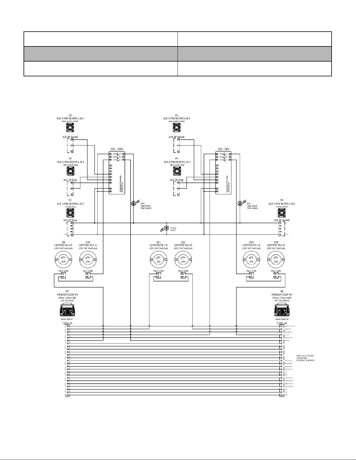
Sensor Connections
The safety interlock adds additional support for 4 wire safety circuits (e.g. bumper switches, pressure
mats). A 4 wire safety circuit when used in conjunction with a safety relay allows monitoring for the
following four conditions:
1. Disconnected - the safety relay sends out test pulses through the sensor and expects the
signal to return. If that signal does not return the safety relay will go into a faulted state and
disallow any further motion.
2. Shorted - if a wire has been crushed by equipment or cut the safety relay will go into a faulted
state.
3. Cross Circuit - if the signals get crossed and the test pulse comes back on the opposite
channel the safety relay will go into a faulted state.
4. Good - if none of the above conditions occur the safety relay will not prohibit any movement.
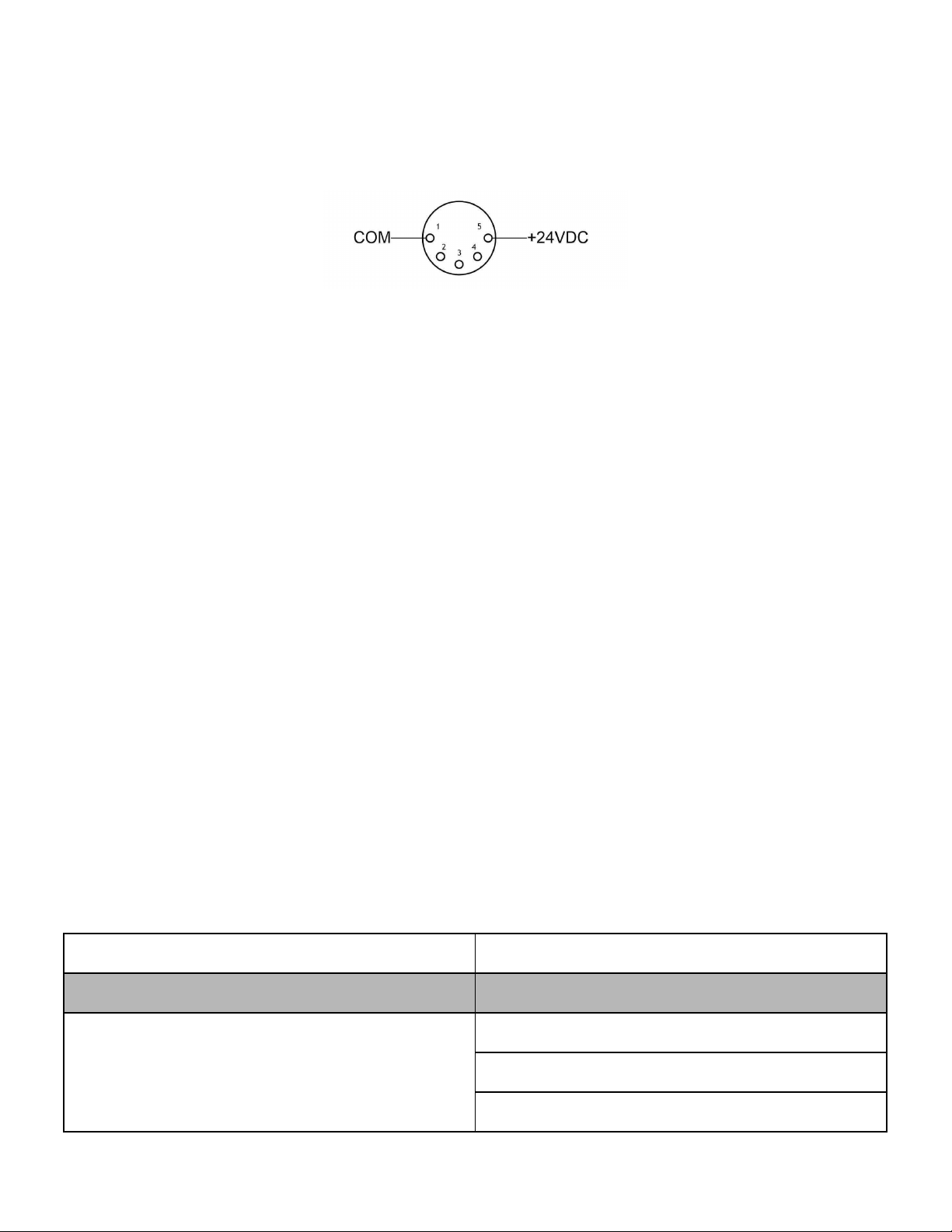
Emergency Stop Connections
The Safety Interlock Pro requires a 24VDC Emergency Stop signal from a Showstopper in order to
allow power to flow to the motor and brakes. Internally, the Stagehand controller has a redundant,
self-monitoring circuit to insure that power will be removed from the motor and brakes instantly if the
24VDC Emergency Stop signal is interrupted. The 5-pin XLR cable is not a DMX signal, but rather it
Page 7 of 10