Creda Newera 79348S User manual

ContactDetails
Pleasenotethatsomeofthecontactdetailson
thisPDFdocumentmaynotbecurrent.
Pleaseusethefollowingdetailsifyouneedto
contactus:
Telephone:08448793588
Email:[email protected]
TheHelpCentresectionofthiswebsitealsofeaturesawiderange
ofinformationwhichmaybeofusetoyouandisavailable24
hoursaday.Itincludes:
•Operatingandinstallationinstructionsdownloads
•Requestarepair
•Wheretobuyourproducts
•Literaturedownloads
•Heatingrequirementcalculator
www.credaheating.co.uk/help‐centre
A division of GDC Group Ltd
Millbrook House Grange Drive Hedge End Southampton SO30 2DF
www.credaheating.co.uk
Re
g
istered No: 1313016 En
g
land
VAT GB 287 1315 50004
EEE Producer Registration Number –
WEE/GE0057TS
Paper from sustainable sources

TSR Supaslim Combi
Combined Storage and Fan Heater
Assembly Instruction
Manual Automatic
Model Nos: 79348S 75772001S
Cat. Nos: TSR12CW TSR12ACW
This product complies with the European Safety Standards EN60335-2-30 and the European Standard Electromagnetic Compatibility (EMC) EN55014, EN60555-2 and EN60555-3.
These cover the essential requirements of EEC Directives 2006/95/EC and 2004/108/EC
© GDC Group Ltd. All rights reserved. Material contained in this publication may not be reproduced in whole or in part, without prior permission in writing.
A division of the GDC Group Ltd, Millbrook House, Grange Drive, Hedge End, Southampton SO30 2DF

IMPORTANT NOTES: It is important to read these instructions carefully and also note the information given on the heater itself.
As these particular instructions refer to the assembly and installation of a new heater, they should be retained by the installer; not left
behind for the user as this would invite the dismantling and servicing by unqualified persons. FOR THE USER, there is a separate
instruction leaflet explaining how the heater should best be operated. Please see that this leaflet is left with the heater for the user’s
purposes. A MEANS FOR DISCONNECTION IN ALL POLES MUST BE INCORPORATED IN THE FIXED WIRING IN ACCORDANCE
WITH THE WIRING RULES, THE INSTALLATION SHOULD BE CARRIED OUT BY A COMPETENT ELECTRICIAN. CABLE HAVING A
MINIMUM ‘T’ RATING OF 85ºC MUST BE USED. Heaters forming part of a comprehensive space heating system should be wired
with their own separate circuit, if however, 1 or 2 heaters are installed as a starter system these may be connected to a 30 amp
ring main provided that the instructions below are observed, any further heaters installed must be connected by its own circuit. If
connected to a 30 amp ring circuit the total rating of heaters connected must not exceed 3kW, where the circuit supplies a kitchen,
or 4kW, where the circuit does not include a kitchen. The storage radiator is designed to run on cheap overnight electricity, therefore
the means of connecting the heater to the ring main should include a timer. These should be connected to the supply with 3 core
heat resistant cable, the size of which is dependant on heater loading i.e. loading up to 10 amps use 1mm², up to 13 amps use
1.5mm² and for the larger heaters 2.5mm² cable. The heater must not be installed immediately below a fixed socket outlet. This
heater must be installed where it is impossible for switches and other controls to be touched by a person using a bath or shower.
WARNINGS - THIS APPLIANCE MUST BE EARTHED - SPECIAL ATTENTION MUST BE PAID TO THE SECURITY OF THE HEATER’S
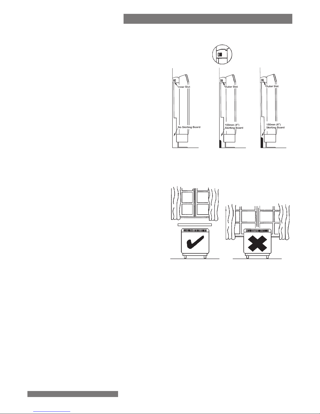
WALL FIXINGS. TO MAINTAIN STABILITY, IT IS ESSENTIAL THAT THE HEATER IS PLACED ON A LEVEL SURFACE AND CARE
SHOULD BE TAKEN TO AVOID IRREGULAR SURFACES, SUCH AS MAY RESULT FROM CARPETS OR TILED SURROUNDS PARTIALLY
PROTRUDING UNDER THE HEATER. Two supplies are taken into this heater, both fan heater and storage heater circuits must be
connected to the same phase of the electricity supply. IF, DURING ANY REASSEMBLY OF THE HEATER, A PART OF THE THERMAL
INSULATION SHOWS DAMAGE OR DETERIORATION WHICH MAY IMPAIR SAFETY, IT SHOULD BE REPLACED BY AN IDENTICAL
PART.
WALL FIXING: The heater must ALWAYS be mounted against, and fixed to a wall as it will not stand up by itself. A detachable
bracket is provided for screwing to the wall, the heater is then placed in position and fixed to the bracket by a screw at each end.
The heater must never be unscrewed or moved from the wall bracket whilst it is loaded with bricks. THE HEATER IS VERY HEAVY
AND WILL BE DANGEROUS IF ITS WALL FIXING BECOMES INSECURE.
Solid Brick and Concrete Walls
No. 10 Rawlplug plastic inserts.
Drill hole of 8mm dia to a depth
of 15mm greater than depth of the
insert.
Panelled Wall, Paramount Board, Chipboard, Plasterboard, etc.
Check that the panel itself is adequately fixed to battens etc. Use Rawlplug
M5 intersets; drill accurate 10mm dia holes in single skin plasterboard.
One fixing should be in studwork.
Hollow concrete, Breeze Block and Thermolite Block Walls
RAWLPLUG ‘RAWLOK R6054R’. Some authorities suggest UNIFIX LB
70/10mm.
Use Drill for accurate hole, not hammer or chisel.
Timber Frame
Seek specialist advice, some authori-
ties suggest RAWLNUT
Storage heaters are not compatible with all types and grades of floor coverings, and in extreme cases damage may occur. It is recommended
that before installation of this product, you check that your floor covering is suitable for exposure to continued high temperatures.
This appliance is not intended for use by persons (including children) with reduced physical, sensory or mental capabilities, or lack
of experience and knowledge, unless they have been given supervision for instruction concerning use of the appliance by a person
responsible for their safety. Children should be supervised to ensure that they do not play with the appliance.

PLEASE DON’T TAKE CHANCES
Site conditions may vary considerably and Creda cannot
recommend the correct wall fixings to be used. It is the
responsibility of the installer to ensure that adequate permanent
fixing has been achieved. Purely for guidance the suggested
fixings are made for certain wall materials but this list is not
comprehensive or authoritative. Different wall constructions will
need different inserts. Note that inserts incorporating plastic may
be subject to shrinkage behind a warm storage heater and are
therefore not recommended.
Wall fixings can be obtained from local stockists
CARPETS: For safety, the heater must be positioned in the room
so that there is at least 75mm (3”) free air space all around
it; under windows, ensure that curtains, when drawn, cannot
touch or cover the heater casing. In order to maintain stability, it
is essential that the heater be placed on a level surface and care
should be taken to avoid irregular surfaces, such as may result from
carpets or tiled surrounds partially protruding under the heater.
The heater feet are designed to go underneath a carpet rather
than standing on it; this permits the weight to be taken on a firm
base. Carpet gripper should be removed from behind the heater
feet. No obstruction to be placed on floor within 300mm of
the front of the heater.
BRICKS: The heater casing and the heater storage bricks with which it must be fitted, are delivered in separate packages. The
brick is common to both heaters, packed in pairs.
The brick catalogue number is 791402015. 7934 and 75772001 models have 8 bricks.

Stand the heater against the wall in its intended position.
Mark the position of the two outside corners of the wall bracket.
Carefully place the heater aside, and remove the wall bracket from the
heater by removing the screw at each end.
Reposition the bracket against the wall using the corner marks for
alignment.
Mark through slots in bracket, two at the extreme ends and the others
spaced evenly between them.
The slots are in groups, allowing mortar courses between bricks to be
avoided, or battens, etc. to be found for the fixing holes.
1
2CARPET FITTING
Cut the underlay and remove carpet gripper to clear feet, allowing heater weight to be
taken on floor proper; lay carpet over feet, slitting it as shown above. It is unnecessary
to cut carpet away.
Open bottom flaps on cartonThe corner fitments contain
the fixing kit.
First, turn carton upside down

WALL FIXINGS - VERY IMPORTANT
A clear space of at least 3” (75mm)
must be left at either side of the heater,
and any projections or shelves must
be at least 10” (250mm) above the
heater casing. Curtains must not
be draped around or in contact with
the casing. A shelf unit is separately
available for fitting above heaters.
4
When bracket is securely fixed, replace
the heater under the bracket angle and
align screw holes on heaters ends.
There are two fixing slots at each end of heater,
allowing different stand-offs for different thicknesses
of skirting board. Do not fully tighten these screws
until the bricks are loaded into the heater as some
settling of the heater may occur.
NOTE: NEVER REMOVE THESE SCREWS WITHOUT
FIRST UNLOADING THE HEATER.
See also figure 2 regarding carpets where
appropriate.
Note: Max. skirting size is 15 x 120mm.
Note that the smallest wall spacing should be used
only when the skirting board is of the modern slim type, or there is no skirting board at all. THE HEATER MUST
STAND VERTICAL
3You must fit a
retaining screw at
each end of the
heater.
NOTE: Removal of the lower front panel is only possible after the top and main front panel assembly has
been removed. First, remove the two black screws situated on the lower front face, then remove the four side
screws. The lower front panel will then pull forward, clear of the heater.
The top panel and front panel are joined and
should be removed as one assembly. To do
this, remove the screws fixing the rear flange
of the top panel, and remove the screws along
the bottom edge of the front panel. Carefully swing out
bottom of front panel and lift assembly clear of casing,
this operation also removes the control knobs under the
flap. Put assembly in a safe place to avoid damage to
paint etc.
5

Charge Rated
Period Charge
79348S
& 75772001S 7 hours 12 kWh
NOTE: The fan heater element is
factory set at full rating. If ½ load rating
only is required the installer should
move the black wire as indicated in the
circuit diagram.
6
Feed the mains cable through the appropriate cable clamp
and make connections as marked on the heater. Pull back
any slack through the clamp and tighten clamping screw.
Make sure clamp is tightening on outer sheath of cable and
not on individual conductors. If mains connection is to be
made from the left hand side, at this point the mains lead
must be secured to the base of the fan box by fixing the
ties provided in the fixing kit through the holes along the
rear of the fan box base.
ENSURE THAT THE CABLES ARE NOT TRAPPED
UNDER THE HEATER LEGS
CONNECTING
THE SUPPLIES
Combi Fan Heater Circuit
MAINS TERMINALS
IMPORTANT: For earthing, loosen the earth screws
sufficiently to wrap the mains’ earth wire around it between
flat washer and cup washer, and retighten the earthing
screw. Both restricted and unrestricted supply wires must be
connected to their respective earthing points.
RESTRICTED
SUPPLY
Storage Heater Circuit
UNRESTRICTED
SUPPLY
RESTRICTED
SUPPLY
79348S
75772001S
ENSURE THAT CABLE
CLAMP IS SECURELY
ATTACHED TO THE
CHASSIS OF THE HEATER.

Remove the inner front panel; this carries on it’s inner face the front
insulation slab. Handle this with care, the insulation must not be
damaged.
REMOVE ALL THE PACKING CARDBOARD FROM INSIDE THE STORAGE
BRICK COMPARTMENT, IF LEFT INSIDE IT WILL BE SET ON FIRE WHEN
THE HEATER IS SWITCHED ON. ENSURE THAT ALL PACKAGING
MATERIAL IS REMOVED FROM THE BRICKS BEFORE FITTING THEM.
Note the way the bricks are positioned in the heater. Otherwise they
will not fit.
WARNING
7
9
11 Now, place in position the front rank of bricks,
again pushing them back to make room for
the front insulation slab which is attached to
the front panel.
Temporarily remove one central element to provide
access for the rear rank of bricks.
Loosen terminals on one of the elements and remove this to allow
installation of rear rank of storage bricks.
8
10 Put in place the rear rank of bricks, pushing them well back
against the rear insulation. Replace the element, making sure
that the connection is tight.

Check that the front insulation slab is properly attached to the inner front
panel and refit panel (insulation innermost) to the heater by locating its
bottom edge behind the front lip of the chassis, and inserting retaining
screws along the top and both sides. With the bricks pushed well back,
as mentioned earlier, and the insulation properly aligned, there should be no bulging of this
panel and no undue force necessary to fix it.
Refit the lower front panel by aligning the four side screws before refitting the front face
screws. With the lower front panel in place, the outer panel assembly can be hooked
over the rear panel top flange and the screws top and bottom replaced and tightened.
Take care not to trap wires or the thermostat capillary between the panel flanges. Ensure all washers are replaced in their
original positions.
Refit the control knobs under the lift - up flap, taking care to align the flat on each spindle.
PLEASE ENSURE THAT ALL POLYSTYRENE AND CARDBOARD PACKING PIECES HAVE BEEN REMOVED.
ENSURE WALL BRACKET SCREWS ARE TIGHTENED FULLY.
WARNING. When a new heater is run up to temperature, the materials will produce a slight smell for the first few days,
these are normally harmless in a well ventilated room. It is best to make these first overnight charges with the ‘Input’
control knob at ‘Maximum’. Caged birds, young children and people with chest ailments are best kept out of the room
for this first period.
12
13
Part No. 88013 Iss. No. 6 12/11
SETTING THE CONTROLS
The controls are located under the lockable flap at the right
hand corner of the top panel. To adjust the controls on the
heater use a coin and engage it in the slot provided on the
top surface of the knob.
AUTOMATIC CHARGING DEVICE (AUTO-SET Fitted only on ‘ACW’ model) The Auto-Set
Control rations the overnight charge each night by sensing the room temperature.
The knob is marked with the numbers 1 to 6, turning the knob to a lower number will reduce the charge consequently,
the level of room warmth the next day.
Once set, the knob should need no further adjustment and the Auto-Set will maintain automatically the room warmth
each day by varying the charge according to the weather.
1. Set the room temperature (output) control knob to setting 4.
2. Turn the Auto-Set Knob clockwise as far as it will go.
3. Leave the heater to run in this condition for two nights in order to quickly disperse the ’new’ smell which although
slight, is better removed once and for all.
4. Instruct the user to set the Auto-Set down to his chosen setting on the third day.
Instructions on this are given in the Users Guide which we ask you to ensure is left with the user.
MANUALLY ADJUSTED HEATER (without Auto-Set Control)
On this the user sets the overnight charge on the numbered knob marked ‘Input’.
Setting up procedure;
1. Turn the ‘lnput’ knob to maximum setting (6)
2. Set the ‘Output’ knob to setting No. 4.
3. Leave the heater to run in this condition for two nights in order to quickly disperse the new smell.
4. Instruct the user to set the ‘Input’ to his chosen setting on the third day. Instructions on this are given in the Users
Guide which we ask you to ensure is left with the user.
Other manuals for Newera 79348S
2
This manual suits for next models
1
Table of contents
Other Creda Electric Heater manuals

Creda
Creda TPR2-750W/TW User manual

Creda
Creda TPRIII 500MT User manual

Creda
Creda NewEra 79341S User manual

Creda
Creda TPR III 500E User manual

Creda
Creda NewEra 79331S User manual

Creda
Creda CSF3 Manual

Creda
Creda NewEra 79331S User manual

Creda
Creda 1FT User manual

Creda
Creda SFH24AW Manual

Creda
Creda Newera 79348S User manual