CREE LIGHTING KBL Series User manual

KBL Series
LED Luminaire
Universal Hook and Cord or Pendant Mount
1 of 6 LPN00513X0001A4_D
INSTALLATION INSTRUCTIONS
INSTRUCTIONS D’INSTALLATION
IMPORTANT SAFEGUARDS
When using electrical equipment, basic safety precautions should
always be followed including the following:
READ AND FOLLOW ALL
SAFETY INSTRUCTIONS
1. DANGER- Risk of shock- Disconnect power before installation.
DANGER – Risque de choc – Couper l’alimentation avant
l’installation.
2. This luminaire must be installed in accordance with the NEC or
your local electrical code. If you are not familiar with these codes
and requirements, consult a qualied electrician.
Ce produit doit être installé conformément à NEC ou votre code
électrique local. Si vous n’êtes pas familier avec ces codes et ces
exigences, veuillez contacter un électricien qualié.
3. Suitable for damp location.
Convient aux emplacements humides.
4. Maximum ambient operating temperature: 9L, 12L, 18L (M) =
50°C and 24L (H), and 30L= 40°C.
Température ambiante maximale de fonctionnement:
9L, 12L, 18L (M) = 50°C et 24L (H), et 30L= 40°C.
5. MIN 90°C SUPPLY CONDUCTORS
LES FILS D’ALIMENTATION 90°C MIN.
6. Check to make sure that all input power connections have been
properly made and the module is grounded to avoid potential
electrical shock.
7. DO NOT lift luminaire by the power cord or any of the cables
connected to the LED heatsink and LED driver.
SAVE THESE INSTRUCTIONS
FOR FUTURE REFERENCE
NOTES:
• Images used in this installation sheet are for illustration purpose,
there are different congurations of the luminaire.
• For each mounting application below, when mounting to surface
ensure that the mounting surface and customer supplied
hardware is capable of supporting the weight of the luminaire.
• The center of mounting is NOT the same as the center of
luminaire.
TO INSTALL:
HOOK AND CORD MOUNT
STEP 1:
Push down on retainer spring until top of spring is free of
luminaire hook. See Figure 1.
STEP 2:
Slide hook into securely mounted customer supplied eye
hanger and return retainer spring to original position.
NOTE: The luminaire should already be factory set for correct
balance. If necessary, the fixture may be balanced by loosening
the hook adjustment screws on the top of the housing and
sliding the hook as necessary for correct balance. Tighten hook
adjustment screws when finished. See Figure 1.
STEP 3:
Make wiring connections per the Electrical Connections
section. After electrical connections for luminaires with a
sensor go to pages 4-6 for installation of sensor.
1
Luminaire Hook
Hook Adjustment Screws
Retainer Spring
1/2” (13mm) IP, 0.875”
(22mm) O.D. Knockout
KBL
KBL WITH ML
SENSOR
KBL WITH PML
SENSOR

2 of 6 LPN00513X0001A4_D
Hinged J-box
3
2
“L” Channel
Pendant Mount Hole
3/4” (19mm) IP, 1.125”
(29mm) O.D.
1/2” (13mm) IP,
0.875” (22mm)
O.D. Knockouts
3/4” (19mm) IP,
1.125” (29mm)
O.D. Knockouts
Adjustment Screws
Hinged Splice
Box
Pendant Slider
Plate
PENDANT MOUNT
STEP 1:
Remove hinged splice box from top of housing
by loosening screw and sliding box to the right
and up from “L” channel. Unhook from hinge
holes. See Figure 2 and 3.
STEP 2:
Remove hook, slider plate and cord and
discard. Plug junction box knockout hole with
provided junction box plug.
STEP 3:
Attach the supplied pendant mount slider plate
using (2) supplied screws (Adjustment Screws).
Use customer supplied 3/4” threaded pendant,
along with two customer supplied locknuts
(one for inside the hinged splice box and one
for outside the splice box). Pull supply leads
into position from customer supplied conduit.
Note: If necessary, the luminaire may be
balanced by loosening (2) screws for pendant
adjustment on the top of the hinged splice box
and sliding the adjustment plate as necessary
for correct balance. Tighten (2) screws when
finished. See Figure 2.
STEP 4:
Attach one end of the hinged splice box to
luminaire by aligning hinge slots on Mounting
Bracket with hinges (on splice box), and then
inserting the hinges into the slots.
STEP 5:
Make wire connections per Electrical
Connections and then push the leads into
hinged splice box. Close the hinged J-box and
re-tighten the screw. See Figure 3.
STEP 6:
Secure other end of the hinged splice box
to luminaire by sliding screw on Mounting
Bracket up and over in “L” channel on the
hinged splice box. See Figure 2.
STEP 7:
Secure luminaire to hinged splice box by
tightening screw.
STEP 8:
For luminaires with a sensor go to pages 4-6
for installation of sensor.
REFLECTOR INSTALLATION
TOOL LESS REFLECTOR:
STEP 1:
Place the reflector over the luminaire
mounting tabs so that the big reflector keyhole
slots align with the tabs. See Figure 4.
NOTE: For aluminum reflectors, insert
two screws, provided with the reflector, for
retention as shown in Figure 4.
STEP 2:
Turn the reflector counter-clockwise until it
locks into place with the locking feature. See
Figure 4.
STEP 3:
To remove the reflector, depress locking tab
and turn reflector clockwise.
Hinged J-box
Screw
4
(4) Keyhole
Slots
(4)
Luminaire
Mounting
Tabs
Locking
Feature
5Loosen
Screws
Add 2 Screws For Aluminum
Reflectors

3 of 6 LPN00513X0001A4_D
STANDARD REFLECTOR:
STEP 1:
Loosen the (4) screws, shown in Figure 5, at least 0.1 inch from the
heatsink.
NOTE: The view in Figure 5 is of the underside of the luminaire.
STEP 2:
Bring trim into housing and line up the (4) screws from Step 1, with the
keyhole slots on the reflector.
STEP 3:
Rotate trim, turn clockwise and tighten the (4) screws from Step 1.
Mounting Lens or Wire Guard To Aluminum Reflector
STEP 1:
Secure the hinge retainer and frame hinge to the reflector using
supplied screw and lock nut. See Figure 6.
NOTE: Reflector is pre-punched at position of this installation.
STEP 2:
Swing the wire guard into place and secure to the reflector with the
attached spring latch. See Figure 6.
Mounting Lens or Wire Guard To Prismatic/ Polycarbonate
Reflector
STEP 1:
Place lens or wire guard onto the bottom of reflector, and place V-band
around lens and reflector. See Figure 7.
STEP 2:
Secure lens or wire guard to reflector by tightening screw on V-band.
See Figure 7.
INSTALLING SAFETY CABLE
NOTE: Safety Cable is sold separately as an accessory, please refer
to installation sheet in safety cable packaging for complete installing
instructions.
STEP 1:
Attach one end of the safety cable through the fin of the heatsink. See
Figure 8.
STEP 2:
Attach other end of the safety cable to mounting surfaces using
customer supplied hardware.
6
Reflector Hinge Retainer
Frame Hinge
Mounting Ring
Reflector
Lens with V-band
Screw
7
Safety Cable
Heatsink
8
ELECTRICAL CONNECTIONS
STEP 1:
Make the following Electrical Connections:
a. For 120/277/347V connect the black fixture lead to the
voltage supply or Hot 1 (for 208/240/480V wiring).
b. For 120/277/347V connect the white fixture lead to the
neutral supply or Hot 2 (for 208/240/480V wiring).
c. Connect the green or green/yellow ground lead to the green
wire position of the terminal block.
STEP 2:
For Dimming make the following Electrical Connections:
NOTE: The incoming signal cable needs to pass through the 1/2”
knockout shown in Figure 3 on page 2.
d. If 0/1-10V Dimming is used, connect the violet lead to the
supply positive dimming lead. If dimming is not being used
ensure to cap off the violet lead.
e. If 0/1-10V Dimming is used, connect the gray lead to the
supply negative dimming lead. If dimming is not being used
ensure to cap off the gray lead.
LINE
OR HOT 1
GREEN
LINE-BLACK
GROUND-GREEN
NEUTRAL-WHITE
DIM (-) GREY
DIM (+) VIOLET
NEUTRAL
OR HOT 2
VIOLET
GREY
SUPPLY WIRING
(DIMMING OPTIONAL)
LUMINAIRE

4 of 6 LPN00513X0001A4_D
Driver Box
Wire
Form
Tabs
Sensor
Adjustment
Screw
9
ML SENSOR INFORMATION
NOTE: For programming of sensor and
more detailed description of sensor visit
https://www.acuitybrands.com/en/products/
detail/575660/sensor-switch/lsxr-series/
fixture-mount-sensor.
INSTALLING SENSOR
STEP 1:
Locate the wire form on the sensor and
install onto the luminaire by inserting the
wire form into the (2) tabs under the driver
box. See Figure 9.
STEP 2:
Ensure that the sensor is leveled. To level the
sensor, loosen the screw on the top side of
the sensor, and retighten the screw once the
sensor is leveled. See Figure 9.
SENSOR DESCRIPTION
The occupancy sensor controls high and low
light levels based on occupancy.
The sensor uses passive infrared sensing
(PIR) technology that reacts to changes in
infrared energy (moving heat) within the
coverage area. Once the space is vacant and
the time delay elapses (adjustable from 30
seconds to 30 minutes), the luminaire will
turn off or dim. Sensors must directly “see”
motion of an occupant to detect them, so
careful consideration must be given to sensor
placement. Avoid placement where sensor’s
line of sight may be obstructed
IMPORTANT: There is an initial warm-up
period. It may take up to a minute before
the lights turn on due to a sensor warm–up
period required during initial power-up. This
occurs during installation or after a lengthy
power failure only.
PML SENSOR INFORMATION
NOTE: For programming of sensor and
more detailed description of sensor visit
https://www.legrand.us/-/media/brands/
wattstopper/.../ws-datasheet-fsp-2x1b.ashx.
INSTALLING SENSOR
NOTE: Ensure that you remove the label on
the unit that says, “Remove This Label Before
Installing Lens”. If this label is not removed,
the sensor will not work properly.
STEP 1:
Rotate the wire form up as shown. The
wire form will snap into position to hold the
Sensor horizontal. Confirm that Sensor screw
is tight. See Figure 10.
STEP 2:
Locate the wire form on the sensor and
install onto the luminaire by inserting the
wire form into the (2) tabs under the driver
box. See Figure 11.
STEP 3:
Rotate Sensor as needed to level position or
adjust field of view.
NOTE: The horizontal position is fixed.
SENSOR DESCRIPTION
The FSP-2X1 is a motion sensor that controls
lighting levels based on occupancy and
ambient light.
The sensors use passive infrared (PIR)
sensing technology that reacts to changes
in infrared energy (moving body heat) within
the coverage area. Once the sensor stops
detecting movement and the time delay
elapses, lights will go from high to low
mode and eventually turn off if it is desired.
Sensors must directly “see” motion of a
person or moving object to detect them, so
careful consideration must be given to sensor
luminaire placement and lens selection.
Avoid placing the sensor where obstructions
may block the sensor’s line of sight. See
Figure 12.
The FSP-2X1 operates on low voltage output
of driver, no power pack is required. It is
designed to be installed in indoor and outdoor
environments. Once the device is initially
powered up, the FSP-2X1 will use factory
default parameters to operate. If adjustments
are needed, the programming tool must be
used.
Light Sensor
IR Transmitter
IR Receiver
PIR Sensor
Motion
Indicator
Red LED
12
Driver Box
Wire
Form
Tabs
Sensor
Screw
11
Wire Form
10

5 of 6 LPN00513X0001A4_D
FSP-2X1 COMMISSIONING
The commissioning process establishes the
appropriate operating parameters of the
FSP-2X1. This is done using the programming
tool.
USING THE PROGRAMMING TOOL
The Wireless IR Programming Tool is a
handheld remote control for setup and testing
of the FSP-2X1. It provides wireless access to
change the parameters of the sensor.
The programming tool displays menus and
prompts to lead you through each process.
The navigation pad provides an intuitive way
to navigate through the customization fields.
See Figure 13.
Within a certain mounting height of the
sensor, 40’ (12.2m) or less, the programming
tool allows modification of the system simply
with the touch of a few buttons, without
requiring ladders or tools.
OPERATION
The programming tool’s IR transceiver allows
bidirectional communication between the
FSP-2X1 and the remote control. Simple
menu screens display the current status
of the system and allow editing of the
sensor parameters, such as high/low mode,
sensitivity, time delay, cut off and more.
You can also establish and store FSP-2X1
parameter profiles.
BATTERIES
The programming tool operates on three
standard 1.5V AAA Alkaline batteries or
three rechargeable AAA NiMH batteries (See
Figure 15). The battery status is shown in the
upper right corner of the home screen (See
Figure 16). Three bars next to BAT= indicates
a full battery charge. A warning appears
on the display when the battery charge
falls below a minimum acceptable level. To
conserve battery power, the programming
tool automatically shuts off 10 minutes after
the last key press.
NAVIGATION
Use the (up) or (down) arrow keys to navigate
from one field to another. The active field is
indicated by a blinking cursor.
Once active, use the Select button to move
to a menu or function within the active field.
Value fields are used to adjust parameter
settings. They are shown in angle brackets:
<value>. Once active, change them using
the (left) and (right) arrow keys. In general,
the (right) key increments and the (left) key
decrements a value. Selections wrap-around
if you continue to press the key beyond
maximum or minimum values. Moving away
from the value field overwrites the original
value. The Home button takes you to the
main menu. The Back button can be thought
of as an undo function. It takes you back one
screen. Changes that were in process prior to
pressing the key are lost. See Figure 14.
For further details on the Sensor, Settings,
Tips and refer to https://www.legrand.us/-/
media/brands/wattstopper/.../ws-datasheet-
fsp-2x1b.ashx.
IR COMMUNICATION
IR communication can be affected by the
mounting height of the sensor and high
ambient lighting such as direct daylight or
other electric light sources in close proximity
When trying to communicate with the FSP-
2X1, be sure to be positioned directly under
the sensor without any obstructions. Every
time the programming tool establishes
communication with the FSP-2X1, the
controlled load will cycle. See Figure 14.
• If communication is not successful, (if
possible) move closer to the sensor.
In some cases, a ladder or lift may be
required
• If still not successful, there may be
too much IR interference from other
sources. Programing the unit at night
when there is no daylight available
may be the only way to communicate
with the sensor.
• If multiple FSP-2X1 sensors are
within the transceiver’s range, all
of the loads may cycle and the “no
response from device” message may
appear on the display.
13
Home Screen
15 16
Distance may vary
depending on
the lighting
environment
max. height
of 40'
14

6 of 6 LPN00513X0001A4_D
www.creelighting.com
© 2019 Cree Lighting, A company of IDEAL INDUSTRIES. All rights reserved. For informational purposes only. Content
is subject to change. See www.creelighting.com/warranty for warranty and specifications. Cree®and the Cree logo are
registered trademarks of Cree, Inc.
TROUBLESHOOTING
NO RESPONSE SCREEN APPEARS:
• Make sure that the sensor is not obstructed.
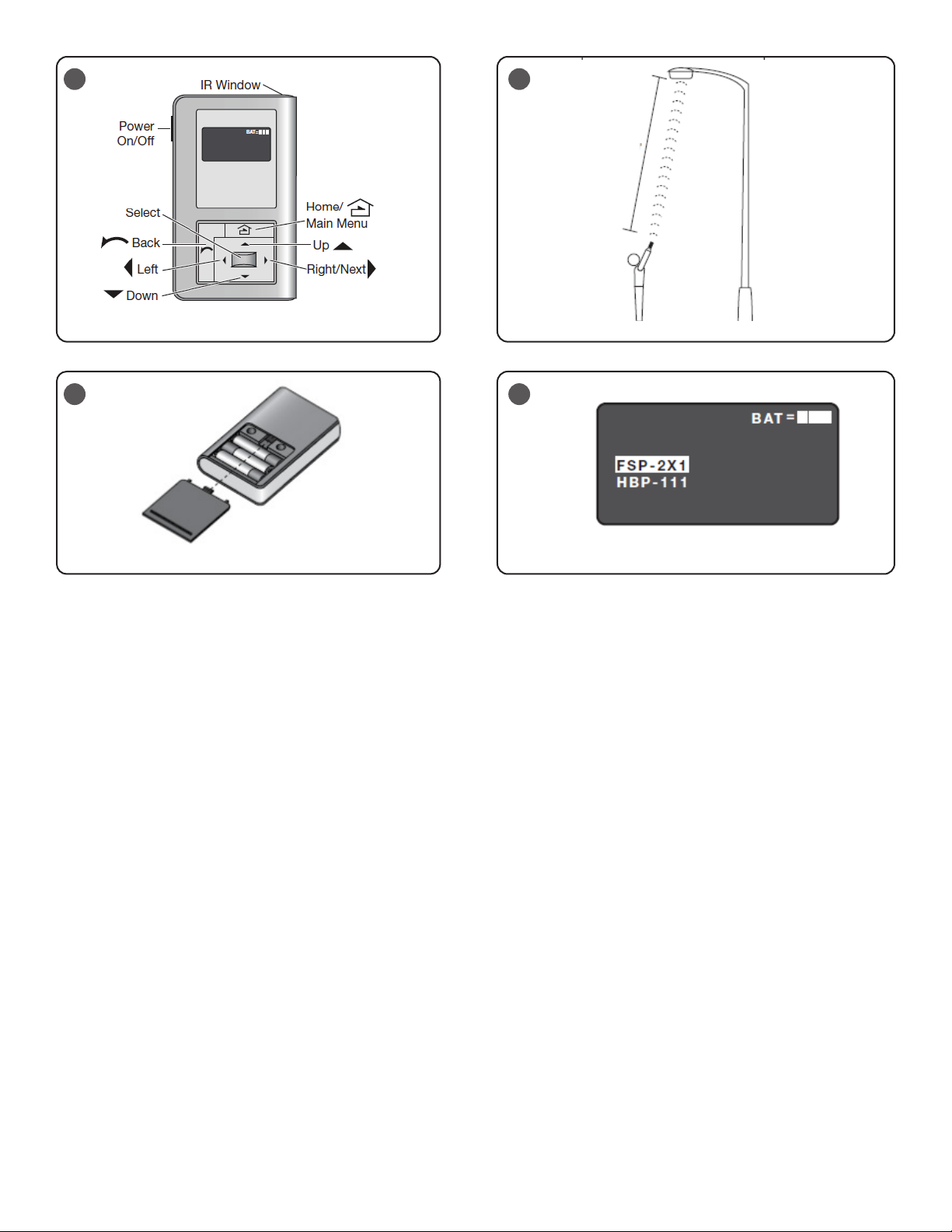
• Move closer to the sensor. A ladder or lift may be required.
• The angle may be too high, move closer so that you are directly
underneath the sensor.
• Make sure that multiple sensors are not in the range of the
transceiver. If this happens, then all of the luminaires will cycle.
• If still not successful, there may be too much IR interference from
other sources. Programming the unit at night may be the only way
to communicate with the sensor.
LIGHTS WILL NOT go to high mode:
• Make sure that the sensor is not obstructed. The sensor must
detect motion to switch to HIGH mode. The red LED indicator will
blink when motion is detected.
• Check the light level parameter, to find out the amount of light
that the sensor is detecting. Cover the sensor lens to simulate
darkness in the room. If the luminaire goes to high mode, then the
setpoint needs to be adjusted to a value greater than the detected
light level. See the new settings and current settings sections for
instructions.
• If the light level is higher than the setpoint value but less than
the photocell value, then the luminaire will remain in low mode.
Adjust the setpoint and photocell values as needed.
• Make sure that the high and low settings are correct by checking
the current settings.
Lights will not go into Low Mode:
The time delay can be set from a minimum of 30 seconds to a maximum
of 30 minutes. Ensure that the time delay is set to the desired value and
that there is no movement within the sensor’s view for that time period.
• To quickly test the unit operation, enable Test Mode and move out
of the sensor’s view. The luminaire should go to LOW mode after 5
seconds.
Lights will not turn OFF:
• Cut Off time may be set to “None.”
• Ensure that the Cut Off is set to the desired time and that there is
no movement within the sensor’s view for that time period when
the lights are in Low Mode.
• To quickly test the unit operation, enable test mode and move out
of the sensor’s view. The luminaire should switch to LOW mode
after 5 seconds and then turn OFF (if cut off is enabled) after 10
sec.
• If the luminaire does not turn off in daylight, check the ambient
light level. Adjust the photocell setting to a value lower than the
ambient light level. The setpoint may also need to be adjusted if
the difference is less than 10 fc.
• Make sure that the Sensitivity field is not set to On-Fix.
Lights will not turn ON:
• Check all wire connections and verify that the load and the ground
wires are tightly secured.
• Check the current settings. If the setpoint value is lower than the
ambient light level, the luminaire will be held OFF. Increase the
setpoint value.
• Disable the cut off function, if not desired.
• Make sure that the Sensitivity field is not set to Off-Fix.
OPERATION DURING POWER-UP
During the sensor warm-up period, which can last up to a minute after
initial power-up (or after a lengthy power outage), the load will remain
ON until the selected time delay expires.
TECHNICAL SUPPORT
If unable to successfully resolve problems with the sensor, contact Cree
Lighting at 800.236.6800 for technical support.
FEDERAL COMMUNICATION COMMISSION INTERFERENCE STATEMENT
CAUTION: Changes or modifications not expressly approved could void your authority to use this equipment.
This device complies with Part 15 of the FCC Rules. Operation to the following two conditions: (1) This device may not cause harmful interference, and (2)
this device must accept any interference received, including interference that may cause undesired operation.
This device has been tested and found to comply with the limits for a Class A digital device, pursuant to Part 15 of the FCC Rules. These limits are
designed to provide reasonable protection against harmful interference when the device is operated in a commercial environment. This device generates,
uses, and can radiate radio frequency energy and, if not installed and used in accordance with the instruction manual, may cause harmful interference
to radio communications. Operation of this device in a residential area is likely to cause harmful interference in which case the user will be required to
correct the interference at his own expense.
INDUSTRY CANADA STATEMENT
This device complies with Industry Canada license-exempt RSS standard(s). Operation is subject to the following two conditions: (1) this device may not
cause interference, and (2) this device must accept any interference, including interference that may cause undesired operation of the device. In addition,
this device complies with ICES-003 of the Industry Canada (IC) Regulations.
Le présent appareil est conforme aux CNR d’Industrie Canada applicables aux appareils radio exempts de licence. L’exploitation est autorisée aux deux
conditions suivantes : (1) l’appareil ne doit pas produire de brouillage, et (2) l’utilisateur de l’appareil doit accepter tout brouillage radioélectrique subi,
même si le brouillage est susceptible d’en compromettre le fonctionnement.
This manual suits for next models
3
Table of contents
Other CREE LIGHTING Lantern manuals

CREE LIGHTING
CREE LIGHTING ZR-RK Series User manual

CREE LIGHTING
CREE LIGHTING Urban Series User manual

CREE LIGHTING
CREE LIGHTING VG Series User manual

CREE LIGHTING
CREE LIGHTING IG Series User manual

CREE LIGHTING
CREE LIGHTING KBL Series User manual

CREE LIGHTING
CREE LIGHTING OSQ Series Installation instructions

CREE LIGHTING
CREE LIGHTING Stylus Series User manual

CREE LIGHTING
CREE LIGHTING Energy Series Installation instructions

CREE LIGHTING
CREE LIGHTING KBL Series User manual