CREE LIGHTING KBL Series User manual

KBL Series
Highbay LED Luminaire with Emergency Driver
Universal Hook and Cord or Pendant Mount
1 of 5 LPN00627X0001A1_D
INSTALLATION INSTRUCTIONS
INSTRUCTIONS D’INSTALLATION
IMPORTANT SAFEGUARDS
When using electrical equipment, basic safety precautions should
always be followed including the following:
READ AND FOLLOW ALL SAFETY
INSTRUCTIONS
1. DANGER- Risk of shock- Disconnect power before
installation.
DANGER - RISQUE DE CHOC - COUPER
L’ALIMENTATION AVANT L’INSTALLATION
2. This luminaire must be installed in accordance with the NEC
or your local electrical code. If you are not familiar with these
codes and requirements, consult a qualied electrician.
Ce produit doit être installé conformément à NEC ou votre
code électrique local. Si vous n’êtes pas familier avec ces
codes et ces exigences, veuillez contacter un électricien
qualié.
3. To reduce the risk of electric shock, disconnect both standard
and emergency power supplies and converter connector of
the emergency driver before servicing.
Pour réduire le risque de décharge électrique, vous devez
déconnecter à la fois le disjoncteur divisionnaire ou les
fusibles et les alimentations d’urgence avant l’entretien.
4. Do not use outdoors.
Ne pas utiliser à l’extérieur.
5. Do not let power supply cords touch hot surfaces.
Ne laissez pas les cordons d’alimentation toucher les surfaces chaudes.
6. Do not mount near gas or electric heaters.
Ne montez PAS près des appareils de chauffage de gaz ou électriques.
7. Equipment should be mounted in locations and heights where it will not readily be subjected to tampering by unauthorized
personnel.
L’équipement doit être monté dans des endroits et à des hauteurs où il ne sera pas soumis à des altérations par des personnes
non autorisées.
8. The use of accessory equipment not recommended by the manufacturer may cause an unsafe condition.
L’utilisation d’accessoires non recommandés par le fabricant peut causer une situation dangereuse.
9. Suitable for damp location.
Convient aux emplacements humides.
10. Maximum ambient operating temperature: 9L, 12L, and 18L(M) = 50°C and 24L, 25L (H), and 30L= 40°C.
Température ambiante maximale de fonctionnement: 9L, 12L, and 18L (M) = 50°C and 24L, 25L(H), and 30L= 40°C.
11. MIN 90°C SUPPLY CONDUCTORS
LES FILS D’ALIMENTATION 90°C MIN.
12. Check to make sure that all input power connections have been properly made and the module is grounded to avoid potential
electrical shock.
13. DO NOT lift luminaire by the cord.
SAVE THESE INSTRUCTIONS FOR FUTURE REFERENCE
NOTES:
• For each mounting application below, when mounting to
surface ensure that the mounting surface and customer
supplied hardware is capable of supporting the weight
of the luminaire.
• The center of mounting is NOT the same as the center
of luminaire.
Maximum Mounting Height in Feet
Lumen output With prismatic diffuser With prismatic diffuser
and conic lens
9L-12L 30 23
18L-30L 44 33

2 of 5
LPN00627X0001A1_D
3
TO INSTALL:
2
“L” Channel
Pendant Mount Hole
3/4” (19mm) IP, 1.125”
(29mm) O.D.
1/2” (13mm) IP,
0.875” (22mm)
O.D. Knockouts
3/4” (19mm) IP,
1.125” (29mm)
O.D. Knockouts
Pendant Adjustment
Hinged Splice
Box
Pendant Slider
Plate
1
Luminaire Hook
Hook Adjustment
Screws
Retainer Spring
1/2” (13mm) IP,
0.875” (22mm)
O.D. Knockout
HOOK AND CORD MOUNT
STEP 1:
Push down on retainer spring until top of spring is free of
luminaire hook. See Figure 1.
STEP 2:
Slide hook into securely mounted customer supplied eye
hanger and return retainer spring to original position.
NOTE: The luminaire should already be factory set for
correct balance. If necessary, the fixture may be balanced
by loosening the hook adjustment screws on the top of
the housing and sliding the hook as necessary for correct
balance. Tighten hook adjustment screws when finished.
See Figure 1.
STEP 3:
Remove hinged splice box from top of housing by
loosening screw and sliding box to the right and up from
“L” channel. See Figure 2.
STEP 4:
Make wire connections per Electrical Connections and
then push the leads into hinged splice box. Replace the
plate and screw. Close the hinged splice box and re-
tighten the screw. See Figure 3.
PENDANT MOUNT
STEP 1:
Remove hinged splice box from top of housing by
loosening screw and sliding box to the right and up from
“L” channel. Unhook from hinge holes. See Figure 2.
STEP 2:
Remove hook, slider plate and cord and discard. Plug
junction box knockout hole with provided junction box
plug.
STEP 3:
Attach the supplied pendant mount slider plate using
(2) supplied screws. Use 3/4” threaded pendant, along
with two customer supplied locknuts (one for inside the
hinged splice box and one for outside the splice box).
Pull supply leads into position from customer supplied
conduit.
Note: If necessary, the luminaire may be balanced by
loosening (2) screws for pendant adjustment on the top of
the hinged splice box and sliding the adjustment plate as
necessary for correct balance. Tighten (2) screws when
finished. See Figure 2.
STEP 4:
Attach one end of the hinged splice box to luminaire by
aligning hinge slots on Mounting Bracket with hinges (on
splice box), and then inserting the hinges into the slots.
STEP 5:
Make wire connections per Electrical Connections and
then push the leads into hinged splice box. Replace the
plate and screw. Close the hinged splice box and re-
tighten the screw. See Figure 3.
STEP 6:
Secure other end of the hinged splice box to luminaire
by sliding screw on Mounting Bracket up and over in “L”
channel on the hinged splice box. See Figure 2.
STEP 7:
Secure luminaire to hinged splice box by tightening
screw.
Hinged
Splice Box Hinged Splice Box
Screw

3 of 5
LPN00627X0001A1_D
REFLECTOR INSTALLATION
TOOL LESS REFLECTOR:
STEP 1:
Place the reflector over the luminaire mounting
tabs so that the big reflector keyhole slots align
with the tabs. See Figure 4.
NOTE: For aluminum reflectors, insert
two screws, provided with the reflector, for
retention as shown in Figure 4.
STEP 2:
Turn the reflector counter-clockwise until it
locks into place with the locking feature. See
Figure 4.
STEP 3:
To remove the reflector, depress locking tab
and turn reflector clockwise.
STANDARD REFLECTOR:
STEP 1:
Loosen the (4) screws, shown in Figure 5, at
least 0.1 inch from the heatsink.
NOTE: The view in Figure 5 is of the underside
of the luminaire.
STEP 2:
Bring trim into housing and line up the (4)
screws from Step 1, with the keyhole slots on
the reflector.
STEP 3:
Rotate trim, turn clockwise and tighten the (4)
screws from Step 1.
Mounting Lens or Wire Guard To
Aluminum Reflector
STEP 1:
Secure the hinge retainer and frame hinge to
the reflector using supplied screw and lock
nut. See Figure 6.
NOTE: Reflector is pre-punched at position of
this installation.
STEP 2:
Swing the wire guard into place and secure to
the reflector with the attached spring latch.
See Figure 6.
Mounting Lens or Wire Guard To
Prismatic Reflector
STEP 1:
Place lens or wire guard onto the bottom of
reflector, and place V-band around lens and
reflector. See Figure 7.
STEP 2:
Secure lens or wire guard to reflector by
tightening screw on V-band. See Figure 7.
6
Reflector Hinge Retainer
Frame Hinge
Mounting Ring
Reflector
Lens with V-band
Screw
7
5Loosen
Screws
4
(4) Keyhole
Slots
(4)
Luminaire
Mounting
Tabs
Locking
Feature
Add 2 Screws For Aluminum
Reflectors

4 of 5
LPN00627X0001A1_D
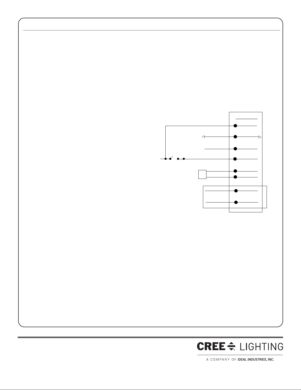
EMERGENCY DRIVER CHECK
NOTE: For short-term testing of the emergency function, the battery
must be charged for at least one hour. The emergency driver must be
charged for at least 24 hours before conducting a long-term test.
STEP 1:
When AC power is applied, the charging indicator light is illuminated,
indicating the battery is being charged. When power fails, the
emergency driver automatically switches to emergency power,
operating the LED array. When AC power is restored, the emergency
driver returns to the charging mode.
STEP 2:
Although no routine maintenance is required to keep the emergency
driver functional, it should be checked periodically to ensure that it is
working. The following schedule is recommended:
• Visually inspect the charging indicator light monthly. It should be
illuminated.
• Test the emergency operation of the fixture at 30-day intervals
for a minimum of 30 seconds. When the test switch is depressed,
the LED array should operate.
• Conduct a 90-minute discharge test once a year. The LED array
should operate for at least 90 minutes.
If the luminaire fails any of these checks, consult service personnel.
REFER ANY SERVICING INDICATED BY THESE CHECKS TO
QUALIFIED PERSONNEL
EMERGENCY DRIVER AND AC DRIVER MUST BE FED FROM THE
SAME BRANCH CIRCUIT.
FEDERAL COMMUNICATION COMMISSION INTERFERENCE
STATEMENT
CAUTION: Changes or modifications not expressly approved could void
your authority to use this equipment.
This device complies with Part 15 of the FCC Rules. Operation to
the following two conditions: (1) This device may not cause harmful
interference, and (2) this device must accept any interference received,
including interference that may cause undesired operation.
This device has been tested and found to comply with the limits for
a Class A digital device, pursuant to Part 15 of the FCC Rules. These
limits are designed to provide reasonable protection against harmful
interference when the device is operated in a commercial environment.
This device generates, uses, and can radiate radio frequency energy
and, if not installed and used in accordance with the instruction
manual, may cause harmful interference to radio communications.
Operation of this device in a residential area is likely to cause harmful
interference in which case the user will be required to correct the
interference at his own expense.
INDUSTRY CANADA STATEMENT
This device complies with Industry Canada licence-exempt RSS
standard(s). Operation is subject to the following two conditions: (1)
this device may not cause interference, and (2) this device must accept
any interference, including interference that may cause undesired
operation of the device. In addition, this device complies with ICES-003
of the Industry Canada (IC) Regulations.
Le présent appareil est conforme aux CNR d’Industrie Canada
applicables aux appareils radio exempts de licence. L’exploitation est
autorisée aux deux conditions suivantes : (1) l’appareil ne doit pas
produire de brouillage, et (2) l’utilisateur de l’appareil doit accepter
tout brouillage radioélectrique subi, même si le brouillage est
susceptible d’en compromettre le fonctionnement.
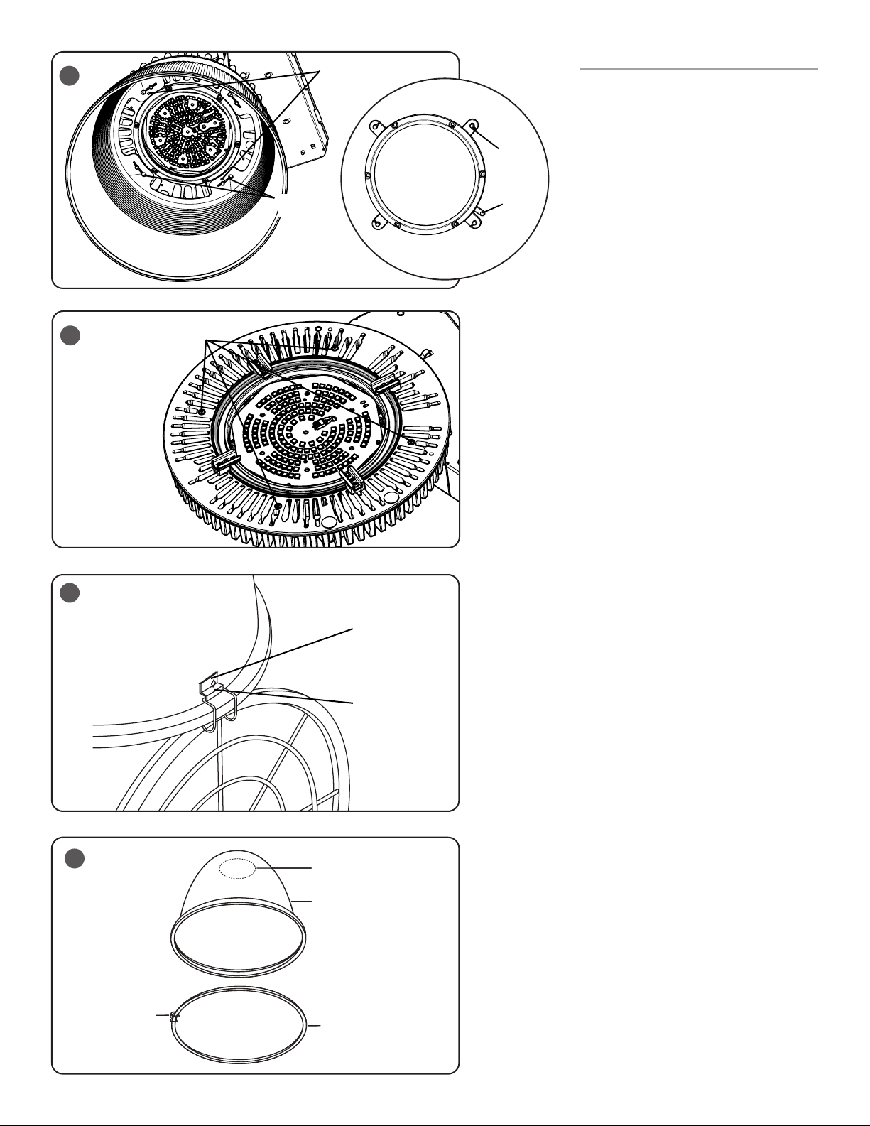
INSTALLING SAFETY CABLE
NOTE: Safety Cable is sold separately as an accessory,
please refer to installation sheet in safety cable
packaging for complete installing instructions.
STEP 1:
Attach one end of the safety cable through the fin of the
heatsink. See Figure 8.
STEP 2:
Attach other end of the safety cable to mounting surfaces
using customer supplied hardware.
Safety Cable
Heatsink
8

5 of 5
LPN00627X0001A1_D
www.creelighting.com
© 2019 Cree Lighting, A company of IDEAL INDUSTRIES. All rights reserved. For informational purposes only. Content
is subject to change. See www.creelighting.com/warranty for warranty and specifications. Cree®and the Cree logo are
registered trademarks of Cree, Inc.
ELECTRICAL CONNECTIONS
NOTE: Luminaire is intended to be wired to a specific voltage.
Make sure that supply voltage matches voltage on electrical
label next to the junction box. Connecting luminaire to voltage
other than that specified on the label may result in luminaire
damage and/or improper luminaire operation. The emergency
driver must be fed from the same branch as the AC Driver.
ELECTRICAL CONNECTIONS MADE IN JUNCTION BOX
STEP 1:
Supply connections can be brought to the junction
box using customer supplied conduit.
STEP 2:
Using customer supplied 90°C minimum rated wire connectors,
make the following electrical connections within the junction box.
a. Connect the black luminaire lead to
the voltage supply hot lead.
b. Connect the white/red luminaire lead
to the supply switched hot.
c. Connect white luminaire lead to the neutral supply lead.
d. Connect green lead to the supply ground lead.
e. If 0/1-10v Dimming is used, connect the violet
lead to the supply positive dimming lead.
f. If 0/1-10v Dimming is used, connect the gray
lead to the supply negative dimming lead.
STEP 3:
Locate the two white leads with connectors located inside the
luminaire junction box and connect them.
ELECTRICAL CONNECTIONS MADE WITH CORD
STEP 1:
Supply connections for dimming leads can be brought to
the junction box using customer supplied conduit.
STEP 2:
Make the following connection from the cord
to customer supplied junction box.
a. Connect the black luminaire hot lead
to the voltage supply lead.
b. Connect the red luminaire lead to the supply switched hot.
c. Connect white luminaire lead to the neutral supply lead.
d. Connect green wire lead to the supply ground lead.
e. If 0/1-10v Dimming is used, connect the violet lead to the
supply positive dimming lead in the luminaire junction
box using 90°C minimum rated wire connectors .
f. If 0/1-10v Dimming is used, connect the gray lead to the
supply negative dimming lead in the luminaire junction
box using 90°C minimum rated wire connectors.
STEP 3:
Locate the two white leads with connectors located inside the luminaire junction box and connect them..
BLACK
WHITE
DIM (-) GREY
DIM (+) VIOLET
NEUTRAL
VIOLET
GREY
SUPPLY WIRING
(DIMMING OPTIONAL)
LUMINAIRE
JUNCTION BOX
VIOLET +
VIOLET
BROWN -
BROWN
ITS
GROUND GREEN
WALL SWITCH
HOT
RED (FOR CORD)
OR
WHITE/RED (FOR
NO CORD)
SWITCHED HOT
HOT
Table of contents
Other CREE LIGHTING Lantern manuals

CREE LIGHTING
CREE LIGHTING OSQ Series Installation instructions

CREE LIGHTING
CREE LIGHTING Urban Series User manual

CREE LIGHTING
CREE LIGHTING IG Series User manual

CREE LIGHTING
CREE LIGHTING VG Series User manual

CREE LIGHTING
CREE LIGHTING Stylus Series User manual

CREE LIGHTING
CREE LIGHTING Energy Series Installation instructions

CREE LIGHTING
CREE LIGHTING KBL Series User manual

CREE LIGHTING
CREE LIGHTING KBL Series User manual

CREE LIGHTING
CREE LIGHTING ZR-RK Series User manual