Cres Cor Tri-Powered Series Manual

5925 Heisley Road • Mentor, OH 44060-1833
Holding Cabinet FL-2361
Rev. 4 (10/13) Page 1 of 12
Cabinet model number:
Cabinet serial number:
Authorized Service Agency:
Ph: Fax:
Keep this manual for future reference.
OPERATING and MAINTENANCE INSTRUCTIONS
Models: HC-UA-11 Tri-Powered Series Hot Cabinets
HC-UA-11
WARNING
IMPROPER INSTALLATION, SERVICE,
ADJUSTMENTS, ALTERATIONS CAN
CAUSE PROPERTY DAMAGE, INJURY
OR DEATH. READ THE INSTALLATION
OPERATING AND MAINTENANCE
INSTRUCTIONS THOROUGHLY
BEFORE INSTALLING OR SERVICING
THIS EQUIPMENT.

5925 Heisley Road • Mentor, OH 44060-1833
Holding Cabinet FL-2361
Rev. 4 (10/13) Page 2 of 12
SUBJECT PAGE
INSTALLATION INSTRUCTIONS .............................................3
OPERATING INSTRUCTIONS ................................................6
Illustration, Figure 1 ..........................................................6
MAINTENANCE INSTRUCTIONS
How to Clean the Unit ...................................................7
Trouble Shooting Guide ..................................................8
Illustration; Cabinet assembly replacement parts ...............................9
Illustration; Control panel assembly ........................................10
Illustration; Burner assembly .............................................11
Wiring Diagram .......................................................12
SERVICE POLICY and AGENCY LIST ....................................FL-1400
TABLE OF CONTENTS
WARNING: TO REDUCE THE RISK OF FIRE OR ELECTRIC SHOCK,
DO NOT REMOVE COVER (OR BACK)
NO USER-SERVICEABLE PARTS INSIDE
REPAIR SHOULD BE DONE BY AUTHORIZED SERVICE
PERSONNEL ONLY
RISK OF FIRE OR ELECTRIC SHOCK
DO NOT OPEN
WARNING

5925 Heisley Road • Mentor, OH 44060-1833
Holding Cabinet FL-2361
Rev. 4 (10/13) Page 3 of 12
INSTRUCTIONS TO INSTALLER BEFORE CONNECTING TO GAS AND ELECTRIC SUPPLIES
1. Retain this manual for further use.
2. Post in a prominent place the following instructions:
FOR YOUR SAFETY
IF YOU SMELL GAS:
1. Open windows.
2. Don’t touch electrical switches.
3. Extinguish any open ame.
4. Immediately remove propane tank,
shut off gas supply or call your gas
supplier.
FOR YOUR SAFETY
Do not store or use gasoline
or other ammable vapors
and liquids in the vicinity of
this or any other appliance.
3. Installation in the United States must conform with the local codes, or in the absence of local codes, with
the NFPA 54/ANSI Z223.1 2012. Installation in Canada must comply with the Installation codes for Gas
Burning Appliances and Equipment, CAN/CSA B149.1-10 and/or local codes.
4. The area around cabinet must be kept free and clear from combustible materials.
5. DO NOT obstruct the ow of combustion and ventilation air. DO NOT block slots or louvers on front and
rear of unit in any way.
6. The cabinet when installed must be electrically grounded in accordance with the local codes, or in the
absence of local codes, with the National Electrical Code ANSI/NFPA 70-2011.
This appliance is equipped with a three-prong (grounding) plug for your
protection. Do not cut or remove the ground prong from this plug.
7. Provisions for adequate air supply, in cabinet area, must be provided.
8. Adequate clearances for servicing and proper operation must be provided.
9. DO NOT ATTEMPT TO OPERATE CABINET DURING A POWER FAILURE.
10. CLEARANCE FROM COMBUSTIBLE CONSTRUCTION, 0 INCHES FROM SIDE AND 0 INCHES
FROM BACK.
11. Wiring diagrams can be found in operating instructions (page 12)
INSTALLATION INSTRUCTIONS
WARNING

5925 Heisley Road • Mentor, OH 44060-1833
Holding Cabinet FL-2361
Rev. 4 (10/13) Page 4 of 12
INSTALLATION INSTRUCTIONS
HC-UA-11 FOR PROPANE CYLINDER INSTALLATION:
This cabinet is not intended for use with natural gas.
It is not user-convertible to natural gas.
1. Only use a 1 lb. standard cylinder marked “PROPANE”. A larger tank can be used with an adapter (optional
accessory part number 0904-026-K See installation FL-2362).
2. The cylinder must be constructed and marked in accordance with the specications for propane cylinders of the
U.S. Department of Transportation (DOT) or CAN/CSA B339.
3. The Cylinder should not be allowed to remain in a high heat area, such as a car, truck or direct sunlight. DO NOT
store at temperatures above 120°F (49° C) and in unauthorized storage areas not intended for cylinder storage.
4. Hold and use the cylinder in an upright position and only use when temperatures are above 10°F (-12° C). Do not
attach near ames, pilot lights or sparks.
5. Propane Tank Hook-up:
a. Make sure the cabinet switch is in the “OFF” position.
b. Uncap the cylinder, hold upright and insert it in the right rear compartment of the cabinet. Hand screw and
tighten the cylinder to the gas regulator. DO NOT over-tighten.
Check for leaks at the connection: Spray soapy water onto the connection and look for bubbles. Tighten more if
needed.
6. Disconnect the cylinder when not in use. Replace the cylinder cap when storing.
HC-UA-11-NG FOR NATURAL GAS INSTALLATION ONLY:
1. Installation shall be made with a connector that complies with Standards for Natural Gas Connection on
Movable Appliances ANSI/Z21.69b/CSA 6.166-2006.
Adequate means to limit the movement of the cabinet without
depending on the connector, quick connect or associated piping
must be provided by the installer.
2. The cabinet and its individual shutoff valve must be disconnected from the gas supply piping system during
any pressure testing of the system at pressures exceeding 1/12 psig (3.45 kPA). During pressure testing
of the gas supply piping system at pressures equal to or less than 1/2 psig (3.45 kPA), the cabinet must be
isolated by closing the manual shutoff valve.
3. Check for leaks at the connection: Spray soapy water onto the connection and look for bubbles. Tighten more if
needed.
WARNING
CAUTION

5925 Heisley Road • Mentor, OH 44060-1833
Holding Cabinet FL-2361
Rev. 4 (10/13) Page 5 of 12
INSTALLATION INSTRUCTIONS
FOR ELECTRIC OPERATION:
Specications: 120 Volts, 1500 Watts, 60 Hz., 1 Ph.
12.5 Amps, 15 Amp. Service (NEMA 5-15P)
Plug the power cord into the proper wall outlet and
push switch to “ELECTRIC”.
Preheat cabinet for 30 minutes.
FOR PROPANE GAS OPERATION:
Specications: (Propane) 8,700 BTU
Connect a propane tank (per Propane Installation
Instructions)
Push the switch to “GAS”. Preheat cabinet for 45
minutes.
NOTES: New tanks may not light on the rst couple
tries. See “Re-light Burner” instructions.
1 lb. propane tank will provide approximately 6 hours
of heat at 160°F.
FOR NATURAL GAS OPERATION:
Specications: 8,700 BTU at W.C.
Notes about using gas:
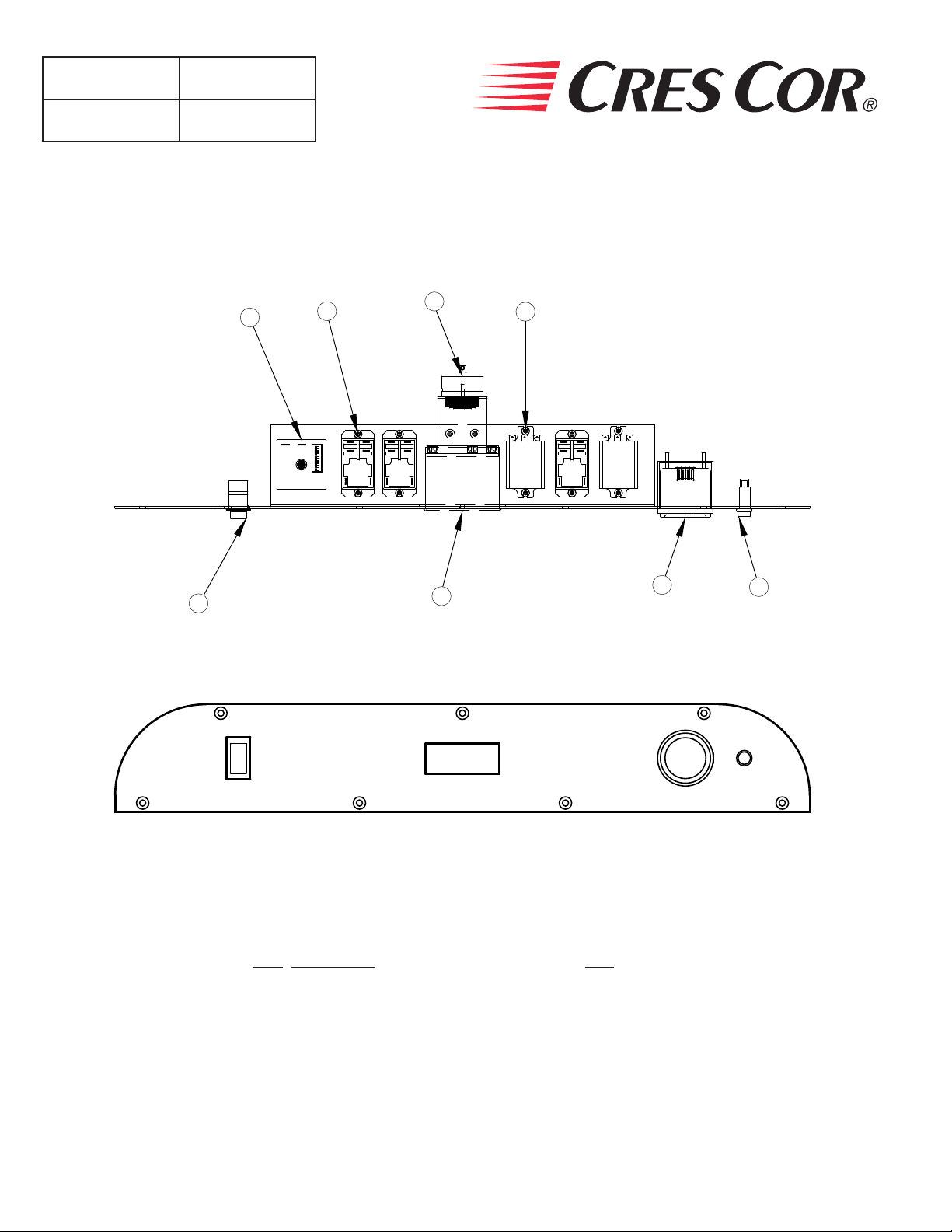
1. GAS RESET LIGHT:
a) Red light on control panel will come on and
an alarm will sound if the ame is not present
when it should be.
b) Propane tank may be empty or a draft has blown
out the burner ames.
c) To re-light the burner: Push switch to “Off”
and then back to “Gas” quickly.
d) Wait for up to 10 seconds and then check sight
glass below the door to see the burner ames.
Repeat as necessary.
Call Service if alarm goes off repeatedly without ignition.
DO NOT ATTEMPT
TO LIGHT BY
HAND.
This cabinet has an automatic ignition system.
2. The battery (needed for the gas valve and the
temperature control) keeps charging as long as the
cord is plugged into the outlet (or when accessory
solar panel is added). Check the battery indicator on
the control panel.
NOTE: The battery will provide power for approximately
16 hours (without solar) before needing a charge;
depending on the age and condition of the battery.
WARNING
GENERAL INSTALLATION:
1. Remove all paper and packing materials from the
inside of the cabinet and install angles into posts.
2. Remove protective paper and vinyl material from
the outside of the cabinet.
3. Place the cabinet in a well-ventilated area on level
oor or ground.
4. DO NOT block the ue vent located at the upper
rear of the cabinet.
5. Lock the two front casters before starting up or
plugging in the cabinet.
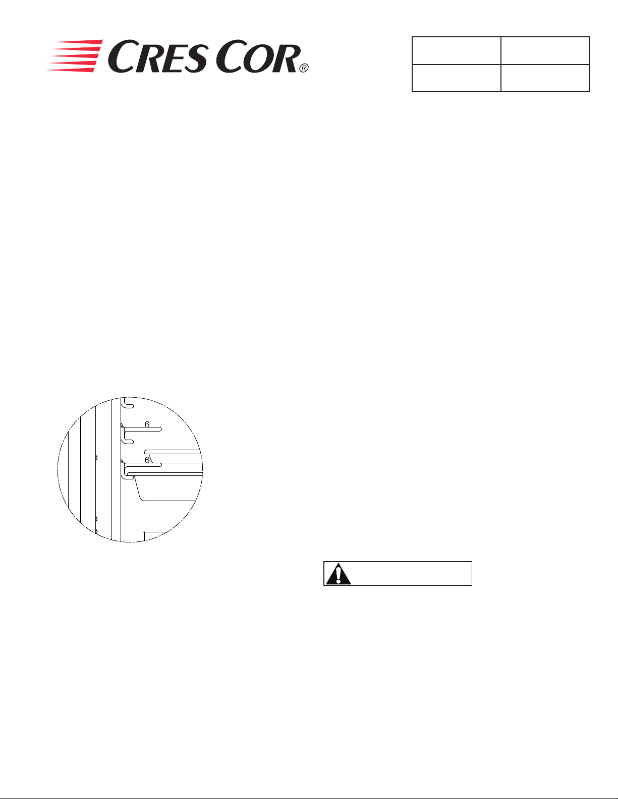
HOW TO INSTALL ANGLES:
1. Insert end tabs of the angles into the post slots
and push down.
2. Note the location shown in the diagram of the
18” x 26” pan slide and the 12” x 20” pan slide
A
DETAIL A
18” X 26” BUN PAN
12” X 20”
STEAM TABLE PAN

5925 Heisley Road • Mentor, OH 44060-1833
Holding Cabinet FL-2361
Rev. 4 (10/13) Page 6 of 12
RESET LIGHT
BATTERY INDICATOR
TEMPERATURE
CONTROL
"ON-OFF" SWITCH
CONTROL PANEL
Figure 1: CONTROL PANEL
WARNING Air is VERY HOT
when door is opened.
FIRST TIME START-UP:
1. Push the POWER switch to “ELECTRIC”, and
run the unit for one hour at 200°F.
NOTE: DO NOT PUT FOOD INTO CABINET!
This step is to burn off manufacturing oils and excess
adhesive.
2. Let the cabinet cool and wipe inside clean with
detergent and hot water before rst use.
USING ACCESSORY SOLAR PANEL (Optional):
The solar panel is used to increase the time between battery charges when using the cabinet unplugged in gas
mode. To use the solar system, ensure the solar panel cord is plugged into the solar jack, located in the top right
corner of the back panel of the unit. Rotate the cabinet and/or tilt the solar panel in order to catch the sunlight.
The best possible condition for solar charging is when the sunrays hit the panel straight on at 90° angle.
NOTE: It is recommended to keep the solar panel plugged in even when not in use. It will safely maintain the
battery at full charge for an unlimited amount of time if not placed in a dark area. The solar system is
not powerful enough to charge the battery from fully drained status in any reasonable amount of time.
If the battery is fully dead, plug the cabinet in to a grounded 120V outlet to charge.
HOW TO HOLD:
1. Push POWER switch on to “GAS” or “ELECTRIC”.
2. Push the “SET” button on the TEMPERATURE
CONTROL. The TEMPERATURE DISPLAY will
show “SP1” (set point 1).
3. Press “SET” again and the current set point temperature
will be displayed.
4. Press the ADJUST buttons to adjust to the
desired temperature.
5. Press “SET” to save the temperature setting.
6. Preheat cabinet for 45 minutes.
7. Put product into cabinet.
NOTE: Proper food holding temperature is
140°F/60°C or higher.
HOW TO HOLD FOOD:
OPERATING INSTRUCTIONS

5925 Heisley Road • Mentor, OH 44060-1833
Holding Cabinet FL-2361
Rev. 4 (10/13) Page 7 of 12
WARNING
BEFORE cleaning the cabinet:
1. Unplug the cabinet from the wall.
2. Allow cabinet to cool.
1. Do NOT use abrasives (steel wool) or harsh
chemicals (chlorine, bromine, iodine or ammonia).
2. Do NOT use a water sprayer (pressure sprayer) to
clean the cabinet.
3. Do not use Cres Clean on label or plastic
materials.
Cleaning hints:
1. Wipe up spills as soon as possible.
2. Clean cabinet daily to avoid heavy dirt build-up.
3. Make a test spot with cleaner:
a) Follow manufacturer’s directions on cleaner.
b) Do not mix cleaners.
c) Avoid drips and splashes.
HOW TO CLEAN THE UNIT:
Soil Cleaner Method
OUTER CABINET
(Powder Coat) WEEKLY, OR AS NEEDED Mild detergent and warm
water.
1. Wipe with clean, soft cloth.
2. Rinse well.
3. Dry gently.
CABINET
Inside and
Door
(Stainless Steel)
DAILY CLEANING Mild detergent and hot
water.
1. Sponge on with cloth.
2. Rinse with water.
3. Wipe dry.
STUBBORN SPOTS AND
STAINS
Mild abrasive made for
stainless steel.
1. Apply with damp sponge or cloth.
2. Rub lightly.
3. Rinse with water and wipe dry.
BURNT-ON FOODS OR
GREASE
Chemical oven cleaner for
stainless steel.
Follow oven cleaner manufacturer’s
directions.
HARD WATER SPOTS
and SCALE Vinegar 1. Swab or wipe with cloth.
2. Rinse and dry.
*Mild detergents include soaps and non-abrasive cleaners.
Note: Door gaskets are removable for cleaning.
MAINTENANCE INSTRUCTIONS
CAUTION

5925 Heisley Road • Mentor, OH 44060-1833
Holding Cabinet FL-2361
Rev. 4 (10/13) Page 8 of 12
FAILURE POSSIBLE CAUSE
1. Unit does not turn on (electric mode). 1a. Power cord is not plugged in.
1b. Branch circuit breaker is tripped.
1c. Fuse is blown.
2. Unit does not turn on (gas mode). 2a. Battery is low on charge. Plug power cord in for at
least an hour to charge battery (this time may vary
depending on state of battery).
2b. Fuse is blown.
NOTE: The power cord can be left plugged in for a long period of time after the battery is fully charged. The
internal battery charger will safely “maintain” the battery.
3. Unit heats up slowly. 3a. Check operating instructions for preheat times.
3b. Defective electrical or gas components.
4. Unit does not heat (electric mode). 4a. Unit is not on.
4b. Thermostat is set too low.
4c. Defective electrical components.
5. Unit does not heat (gas mode). 5a. Unit is not on.
5b. Thermostat is set too low.
5c. Propane/gas tank has expired.
5d. A gust of wind may have blown out the ame or
prevented ignition of the gas.
5e. Defective electrical components.
NOTE: The control is equipped with an auto-ignite system. On startup and periodically throughout operation,
it will attempt to ignite the gas for 10 seconds. If it fails, the “reset” indicator will illuminate and an
audible alarm will sound, indicating no heat. If the tank is empty, this will usually happen within 20
seconds, in windy conditions, it could take up to 5 minutes for the alarm to become present. If this
happens, turn the power switch to “OFF” and then back to “GAS”, and it will try to re-ignite.
6. Unit gets too hot or won’t shut off. 6a. Defective electrical components.
For repairs, refer to our list of Authorized Service Centers, FL-1400
NOTE: If any panel which is sealed with silicone needs to be removed for servicing by an authorized personnel,
the exterior seams need to be sealed with a food grade caulking material (certied against NSF/ANSI 51).
TROUBLE-SHOOTING

5925 Heisley Road • Mentor, OH 44060-1833
Holding Cabinet FL-2361
Rev. 4 (10/13) Page 9 of 12
REPLACEMENT PARTS
Include all information on nameplate when ordering parts
Cabinet Assembly:
ITEM DESCRIPTION 120V
1Door Assembly 1221-596-K
2 Hinge (2 per kit) 0519-110-K
3 Latch 1006-143-K
4 Gasket, Door 0861-182-K
5 Casters, Rigid 0569-281-RK
6 Casters, w/Brake 0569-281-BK
7 Wire Angles (2 per kit) 0621-352-K
8 Posts 0696-169
9 Sight Glass 0574-167
18 Cord Set 0810-149
19 High Limit, 400°F 0848-033
20 High Limit 0848-060
21 Flanged Inlet 0713-011
22 Socket, DC Elec. Conn. 0713-059
23 Fuse 0807-151
24 Fuse Holder 0807-150
25 Heater (1500W, 120V) 0811-310
26 Battery Kit w/Charger 7037-008-K (Before 9/2013)
Battery 7037-008 (After 9/2013)
Solar Panel Kit 7037-001-K
Large Tank Adapter 0904-026-K
26
1
2
3
4
5
6
7
8
9
2019
18
21
22
23 24
X:\ENGINEER\FLSHEETS\FL2361\FL-2361-CAB.dwg

5925 Heisley Road • Mentor, OH 44060-1833
Holding Cabinet FL-2361
Rev. 4 (10/13) Page 10 of 12
REPLACEMENT PARTS
Include all information on nameplate when ordering parts
Control Panel Assembly:
ITEM DESCRIPTION 120V
10 Power Switch 0808-126
11 Temperature Control 0848-075-CC
12 Battery Indicator 7037-004
13 Reset Light 0766-100
14 Timer, Delay 0849-096
15 Relay 0857-139
16 Alarm, Audible 0908-008
17 Relay, 3DPDT 0857-135
10 11 12 13
14 15 17
16
CONTROL PANEL ASSEMBLY
X:\ENGINEER\FLSHEETS\FL2361\FL-2361-CP2

5925 Heisley Road • Mentor, OH 44060-1833
Holding Cabinet FL-2361
Rev. 4 (10/13) Page 11 of 12
WIRING DIAGRAM
Burner Assembly:
ITEM DESCRIPTION 120V
26 Terminal Block 0852-093
27 Relay DPDT 0857-130
28 Battery 7037-003
29 Battery Charger 7037-005
30 Burner Assembly, Complete 8100-001
31 Control Module 8100-001
32 Regulator (Solar) 7037-002
33 Gas Burner 8100-002
34 Igniter 8100-005
35 Gas Valve 8100-008
36 Regulator 8100-009
37 Pressure Switch 8100-011
38 DC-DC Converter 0769-201
39 Flame Sensor 8100-002
8100-015 BURNER ASSEMBLY
PROPANE TANK
HOOK-UPAREA
x:\engineer\flsheets\fl2361\fl-2361-burn.dwg
BATTERY
VALVE CONTROL
MODULE
33 35 37
36
38 29 32 26 31
34
39
28
27

5925 Heisley Road • Mentor, OH 44060-1833
Holding Cabinet FL-2361
Rev. 4 (10/13) Page 12 of 12
WIRING DIAGRAM
FL-0156, REV.11/17/03
FRONT PANEL
TEMPERATURE
CONTROL
12V INPUT
NOC
POWER SWITCH
gas-o-electric
BATTERY
12V
+-
brwn blue
L2
L1
TB1
RELAY 1
HIGH
LIMIT
400°F
HTR.
BATTERY LIFE
INDICATOR RESET
WARNINGS
SOLAR REGULATOR
SOLAR PANEL
PRESSURE
SW.
BATTERY CHARGER
VALVE CONTROL
GAS VALVE
main pilot
FLAME SENSOR
IGNITOR
DC-DC
CONVERTER
12V -> 6V
INPUT
++
--
OUT OUT
T/C
RELAY 1 - LOCKOUT
3PDT, 120VAC COIL
RELAY 2 - PROPANE
DPST, 12VDC COIL
RELAY 3 - ELECTRIC
DPST, 12VDC COIL
RELAY 4 - RESET
DPST, 12VDC COIL
RELAY 5 - DECIDER
3PDT, 120VAC COIL
RELAY 6 - ELEC. HTR.
DPDT, 120VAC COIL
RELAY 2
RELAY 3
RELAY 4
RELAY 5
RELAY 6
+
-solar battery
+-
+
-
TIME
DELAY
1
3
t°
HIGH
LIMIT
300°F
+-
REAR PANEL
PWR CORD
3
1245 6 789
10
11121314151617 18
19
20
21
22
23
31
30
29
28
27
26
25
24
24
25
26
27
28
29
30
31
38
37
36
34
33
32
3940
32 33
34
35
36
37
38
39
40
41
42
43 44
45
46
41 42
44
45
46
4748 495051525354 63
62
61
60
59
58
57
56
55 69
68
67
66
65
64
47
48
49
50
51
52
53
54
55
56
57
58 59
60
61
62
63 64
65
66
67
68
69
70
72
72
73
73
74
74
75
75
76
76
77
77
78
78
79
79
80
80
81
82 82
83 83
84
84
85 85
109
88
88
91
91
93
93
94
94
95
95
98 99
100 100
101 102
103
104 105
DC PWR
CONNECTOR
96
97
111 110
111
110
108
109
AUDIBLE
ALARM
VISUAL
ALARM
PLUG SOCKET
86
87
TB2
TB1 - 12V
TB2 - 120V
SEE WIRING INSTRUCTIONS FOR ADD'L INFO.
RED PAINT ON VISUAL ALARM INDICATES (+)
106 107
43
81
71
112
112
35
A
A
FUSE
GROUND*
GROUND*
GROUND*
AB
4
7
1
9
6
3
AB
4
7
1
9
6
3
10
4
8
6
2
2
5
8
10
4
8
6
2
10
4
8
6
2
AB
4
7
1
9
6
3
2
5
8
RED
12VDC
+-
19
19
1
4
19
P7
P8
P9
P10
P11
P12
P1
P2
P5
P6
P3
P4
P13
P14
This manual suits for next models
1
Table of contents
Other Cres Cor Food Warmer manuals

Cres Cor
Cres Cor CCB-120A Manual

Cres Cor
Cres Cor CCB-150 Series Manual

Cres Cor
Cres Cor H137UA C Series Manual

Cres Cor
Cres Cor 1000HHSS2DE Manual

Cres Cor
Cres Cor H137WSUA5DMFBC Manual

Cres Cor
Cres Cor Hand-Lift Cabinet H-339214 Manual

Cres Cor
Cres Cor Banquet Warming Cabinet CCB150 Series Manual

Cres Cor
Cres Cor HC1-UA-11 Manual

Cres Cor
Cres Cor Banquet Warming Cabinet EB-150 Manual

Cres Cor
Cres Cor IFW 66 Series User manual