Crestron Green Light GLPS-HDSW-FT Guide

North America Edition


Crestron Commercial Lighting Design Guide
i
Table of Contents
Introduction........................................................................................................................................................ 1
Totally Integrated Building Control ................................................................................................................... 2
Specifying Crestron Lighting Systems.............................................................................................................. 3
Cresnet and Ethernet........................................................................................................................................................................3
System Architecture.........................................................................................................................................................................3
Centralized Architecture .................................................................................................................................................................4
Distributed Architecture .................................................................................................................................................................5
Hybrid Architecture ........................................................................................................................................................................6
Product Families...............................................................................................................................................................................7
Common Applications ....................................................................................................................................................................7
Written Specifications......................................................................................................................................................................8
Green Light Designer Software........................................................................................................................................................8
Lighting Systems ............................................................................................................................................... 9
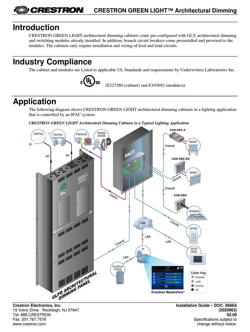
Architectural Dimming .....................................................................................................................................................................9
When to Specify Architectural Dimming..........................................................................................................................................9
GLPD Panels ................................................................................................................................................................................11
GLPD-C Panels.............................................................................................................................................................................13
Module Specifications ..................................................................................................................................................................15
Cabinets.......................................................................................................................................................................................18
Power Switching.............................................................................................................................................................................19
When to Specify Power Switching ................................................................................................................................................19
GLPS Panels.................................................................................................................................................................................21
GLPS-C Panels.............................................................................................................................................................................23
Module Specifications ..................................................................................................................................................................25
Cabinets.......................................................................................................................................................................................28
Green Light Express .......................................................................................................................................................................29
GLPX Panels.................................................................................................................................................................................30
Module Specifications ..................................................................................................................................................................31
DALI.................................................................................................................................................................................................35
When to Specify DALI Systems.....................................................................................................................................................35
Products ......................................................................................................................................................................................36
Room Solutions...............................................................................................................................................................................39
When to Specify Room Solutions ..................................................................................................................................................39
GLPAC-DIMFLV ............................................................................................................................................................................40
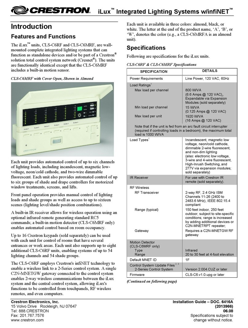
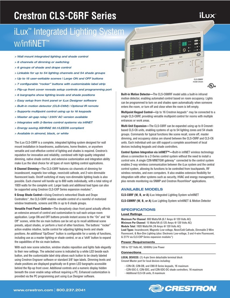
iLux..............................................................................................................................................................................................42
Cameo Dimmers and Switches.....................................................................................................................................................45
Processors ....................................................................................................................................................... 48
PAC2................................................................................................................................................................................................48
PAC2M.............................................................................................................................................................................................49
IPAC-GL1.........................................................................................................................................................................................50
DIN-AP2...........................................................................................................................................................................................51
User Interfaces................................................................................................................................................. 52
Wired Touchpanels.........................................................................................................................................................................52
Handheld Wireless Touchpanels....................................................................................................................................................54
Keypads ..........................................................................................................................................................................................56
Cameo®.......................................................................................................................................................................................56
HTT-B10EX ..................................................................................................................................................................................57
Decorator.....................................................................................................................................................................................58
Crestron Commercial Lighting Design Guide
ii
Designer ......................................................................................................................................................................................59
Mobile Interfaces............................................................................................................................................................................60
Crestron Mobile Pro®...................................................................................................................................................................60
Crestron Mobile Pro G ..................................................................................................................................................................60
XPanel & XPanel for Mac..............................................................................................................................................................60
Sensors............................................................................................................................................................. 61
The Sensor Advantage .................................................................................................................................................................61
Automated Actions.......................................................................................................................................................................61
Occupancy Products ....................................................................................................................................................................61
Light Sensors...............................................................................................................................................................................62
Partition Products.........................................................................................................................................................................62
Sensor Interfaces .........................................................................................................................................................................62
Shades.............................................................................................................................................................. 63
How We Control ...........................................................................................................................................................................63
How We Integrate.........................................................................................................................................................................63
Accessories...................................................................................................................................................... 65
Viridian ............................................................................................................................................................. 70
Integrated Energy Management Software.....................................................................................................................................70
Sample Screen Shots...................................................................................................................................................................71
Appendix A - Touchpanel Graphics................................................................................................................. 72
Appendix B - Common Keypad Layouts.......................................................................................................... 74
Appendix C - Glossary of Lighting Terms ....................................................................................................... 75

Crestron Commercial Lighting Design Guide
1
Introduction
Introduction
This guide is designed to educate you on lighting system design using the wide
range of products found in the Crestron Green Light®family. Crestron Green Light
is built on 40 years of expertise, vision, and innovation. From the very first
touchpanel to the first Ethernet-based control system, Crestron has defined
“integration.” Focused on bringing to market new and advanced solutions for
making life easier and greener, Crestron is continuing to engineer the future of
intelligent building technology.
Through our industry experience, we understand the value of scalability. We know
that the needs (and budgets) of today may be different tomorrow. Green Light
solutions are uniquely designed to grow over time while constantly providing a
reliable and consistent user experience. Solutions for the room can expand to fulfill
the needs of the entire building; a building may grow into a worldwide enterprise.
Crestron delivers solutions for venues and projects of all sizes.
Product scalability is crucial, but hardware is only as good as the software that
drives it. Crestron software tools are designed to integrate all areas of the system
to do anything you want them to do. Lights in a boardroom originally designed to
function locally can now hook into the room’s AV system for an integrated solution,
so when the source is switched to Blu-ray, the lights automatically dim. Similarly,
electric shades that were only intended to lower during AV presentations can now
be integrated to intelligently lower based on the angle of the sun and lumen level.
This data is shared with Crestron RoomView®Server Edition software across the
global enterprise for energy tracking, monitoring, control and maintenance.
With Crestron, everything can be integrated and intelligently managed. This is the
power of Crestron: a solution that evolves with you. Welcome to Crestron—the only
solution solving the challenges of today and tomorrow.

Crestron Commercial Lighting Design Guide
2
Totally Integrated Building Control
TOUCHPANEL AV RACK/
PROCESSOR
PARTITION
SENSORS
CO2,
HUMIDITY &
TEMPERATURE
SENSORS
OCCUPANCY
& PHOTOCELL
SENSORS
SHADES
VAV / FCU
CONTROL
KEYPAD
S
T
LIGHTS
LIGHTS
TEMP
VOLUME
VOLUME
TEMP
S
T
S
T
CONFERENCE ROOM / CLASSROOM
LIGHTING
PUBLIC AREAS / OPEN OFFICE HOTEL ROOM / PATIENT ROOM
PARKING / EXTERIOROFFICES
RoomView™
ENTERPRISE
SERVER
MECHANICAL
BMS
PROCESSOR
SECURITY
SERVER
FIRE /
LIFE SAFETY
PROCESSOR
CO2,
HUMIDITY &
TEMPERATURE
SENSORS
S
S
S
OCCUPANCY
& PHOTOCELL
SENSORS
SHADES
VAV / FCU
CONTROL
POWER
SENSING
DALI
BALLASTS PARTITION
SENSORS
CO2,
HUMIDITY &
TEMPERATURE
SENSORS
OCCUPANCY
& PHOTOCELL
SENSORS
SHADES
VAV / FCU
CONTROL
POWER
SENSING
LIGHTING
®
CRESTRON
Power
Switching
Cabinet
Lighting
Processor
CRESTRON
OCCUPANCY
& PHOTOCELL
SENSORS
LIGHTING
LED
LIGHTING
VENTILLATION
CO / CO2
SENSORS
KEYPAD
LIGHTSON
LIGHTSOFF
SHADE
SHADE
S
T
CO2,
HUMIDITY &
TEMPERATURE
SENSORS
OCCUPANCY
& PHOTOCELL
SENSORS
VAV / FCU
CONTROL
SHADES
NET
NETID
24 Y Z G 24 Y Z G
2-CHANNELDALI INTERFACE
WITHBUS POWER SUPPLY
DIN-DALI-2
CRESTRON
SETUP NET
OVR PWR
COMPUTER
INT EXT
DALIPOWER
DALI1 DALI2
TEST
OVERRIDE
OVRG OVRG
RESET
LANPoE
+ - + - + - + -
DALI
CONTROLLER
LIGHTING
PRESENTATION
SYSTEM
KEYPAD
S
T
LIGHTS
LIGHTS
TEMP
VOLUME
VOLUME
TEMP
S
T
S
T
LIGHTING
CONTROLLER
INDUSTRIAL
CONTROL
EQUIPMENT
USC UL
R
CAUTION: RISK OF ELECTRIC SHOCK - MORE THAN ONE
DISCONNECTSWITCH MAY BE REQUIRED TO DE-ENERGIZE
THEEQUIPMENTBEFORE SERVICING.
AVERTISSEMENT:CET ÉQUIPEMENT RENFERME PLUSIEURS
CIRCUITSSOUSTENSION. VOIRLE SCHÉMA
PRECAUCION:PELIGRO DE ELECTROCUCION - SE REQUIERE
LA DESACTIVACION DE MAS DE UN INTERRUPTOR PARA
CORTAREL SUMINISTRO DE ENERGIA ELECTRICA AL EQUIPO
ANTESDEEFECTUAR SERVICIO.
ALLCOVER MOUNTING SCREWS MUST BE INSTALLED AND
TIGHTENEDTOASSURE PROPER GROUNDING.
NOUSERSERVICEABLE PARTS UNDER THIS COVER.
CAUTION:SEE INSTRUCTION MANUAL FOR INSTALLATION,
OPERATION,ANDMAINTENANCE INSTRUCTIONS.
ENERGYMANAGEMENT FEATURES:
DIMMING
SWITCHING
SCHEDULING
LOADSHEDDING
OCCUPANCYSENSING
DAYLIGHTHARVESTING
ENERGYUSAGEMONITORING
NETWORKMONITORINGAND CONTROL
CONTRIBUTESTOLEED CERTIFICATION
MEETSASHRAE90.1 REQUIREMENTS
MEETSCECTITLE 24 REQUIREMENTS
USGBCMEMBER
®
BUILDING MANAGEMENT
Metasys
Totally Integrated Building Control
Imagine having total control over all building technology, across any number of locations, from a single easy to use interface. Only
Crestron makes it possible. With everything combined into one Crestron system, managing enterprise locations is easier than ever
before. With Viridian software, monitoring, tracking, and controlling resources is simply a click or touch away.
Modern commercial buildings are increasingly complex. Lighting, AV, HVAC, security, and other systems are all necessary in today’s
office. Crestron control processors easily interface with these systems. Lighting and AV systems are available directly from Crestron.
Other building technology, such as HVAC or security, is easily connected through a GLA-BMS or by directly connecting to a Crestron
control processor.
The graphic below depicts how Crestron can control a commercial building. Individual rooms have different solutions to their differing
needs, but all are connected via the Crestron control system. Blue circles represent pieces available directly from Crestron. White circles
are pieces provided by a third party (such as a television or light fixture).

Crestron Commercial Lighting Design Guide
3
Specifying Crestron Lighting Systems
This lighting design guide will help you choose the proper Crestron products for your application. A typical lighting system has at least a
lighting control module or cabinet, a processor, and a user interface. Follow these basic steps when navigating through this guide:
1. Survey all controlled lights and loads
Gather information on wattage, voltage, and fixture type. Specify each load as dimmed or switched, normal or emergency, and
central or local control.
2. Choose one or more lighting systems
Use the Product Families section to help you choose. Designate each load to a lighting system. Make sure not to exceed the
maximum load rating for each lighting system.
3. Choose one or more control processors
Use the Processors section. Room Solutions products can work without a processor, but may have limited expansion without
one.
4. Choose one or more user interfaces
For iLux®and wall box dimmers and switches, a separate user interface is not necessary, but recommended.
5. Add in sensors, shades, and accessories for a more powerful system
Crestron’s Green Light Designer program can help with the design process. Currently, it supports Architectural Dimming, Power
Switching, and iLux systems. For more information see the Green Light Designer Software section.
Cresnet and Ethernet
Throughout the design process, it is important to consider communication between devices. Almost every product in this guide is
capable of connecting via Cresnet. Cresnet is the communications backbone for Crestron systems. It is a simple, bi-directional network
combined with a 24 V power feed. Cresnet allows runs over several thousand feet, and the wiring topology is flexible. Unlike Ethernet,
there is no need for dozens of “home-run” cables – Cresnet can daisy-chain
and
home-run.
When designing, try to avoid a large number of Cresnet devices on one circuit. There is a physical limit of 255 devices per segment, but
performance may limit you to far less devices. The acceptable number of Cresnet devices varies with usage and programming
complexity. Performance can be increased by using the Cresnet hubs described in the accessories section of this guide. The PAC2
processor includes several Cresnet segments built-in for high performance out of the box.
Cresnet supplies 24 V power to devices. Power is provided by select processors or a power supply. Insufficient or unstable power will
cause an unreliable system. To help you with the power calculations, a power calculator is available on the Crestron web site.
An Ethernet connection is available on some products, especially touchpanels and processors. Ethernet provides a high performance
connection. Power can be provided with devices that support POE (Power Over Ethernet).
System Architecture
Crestron Green Light systems are available in a variety of configurations. Factors such as construction type, client requirements, and
architectural restrictions determine the best configuration. Lighting system architectures include centralized, distributed, and hybrid.
At the heart of each Green Light system is one or more control processors. This control system takes in user button presses or other
external events and turns them into single commands or even sequences of commands; dimming lights and closing shades can occur
with just one button press or occupancy sense. In addition to controlling lighting, fans, motors, HVAC, and security, the control system
can connect to building systems via Ethernet, RS-232, BACnet, LonWorks, and others.

Crestron Commercial Lighting Design Guide
4
Specifying Crestron Lighting Systems
Centralized Architecture
Product Families: Architectural Dimming, Power Switching, Green Light Express
xHigh-voltage wiring home-runs from many rooms to a central Crestron panel
xLights are controlled with keypads and touchpanels located anywhere
In a centralized system all the high-voltage lighting, motor, fan, and switch circuits draw power directly from modules in a Crestron
Green Light enclosure. Wired or wireless user interfaces can be placed throughout the building to control the various circuits. A
centralized design simplifies the high-voltage wiring through a “home-run” infrastructure in which each lighting circuit is connected
directly to the module within the Crestron enclosure.
The major benefit of a centralized architecture is the ability to program the user interfaces to control any load connected to the system.
This differs from traditional distributed infrastructure, whereby each circuit is controlled locally via the in-wall dimmer or switch.
Enabling load control through programming enables multi-point control as well as the ability to change how the system functions
through future updates. In addition to reducing wall clutter, multiple circuits can be controlled via a single button press, simply recalling
presets for different room configurations, events or atmospheres.
Centralized systems are appropriate for applications such as lobbies, hallways, parking garages, stadiums, and auditoriums.
R
R
R R R
R R R
GLPS
CABINET
M
M
Wireless
Touchpanel
Touchpanel
Keypad KeypadKeypadKeypad
Touchpanel
Office 1 Office 2 Office 3 Office 4
Boardroom
Auditorium
Parking
Lot
R
Troffer
Recessed
Track
Parking
KEY
Shade Motor 120/277V
Control
M

Crestron Commercial Lighting Design Guide
5
Specifying Crestron Lighting Systems
Distributed Architecture
Product Families: Room Solutions
xWired in traditional configuration
xEach load is controlled by a local Crestron device
xIn some cases, the local device has integrated keypad
xKeypad and touchpanel control are optional, allowing that load to be controlled from any location
In a distributed system, the high-voltage lighting, motor, fan, and switch circuits are wired in the traditional configuration with local
control. Controllable in-wall dimmers or switches replace the standard dimmers or switches and can be retrofitted into a project after
customary high-voltage wiring is completed. Crestron in-wall dimmers communicate with a control processor through either a Cresnet
(low-voltage control wire) or infiNET EX™(mesh RF) wireless connection. This design combines the familiarity of local control with the
power and flexibility of automation. In the event of a control system interruption, the user can still operate the lighting locally.
In the commercial space, in-wall solutions are appropriate for offices, small boardrooms, and hospitality. Typically in-wall dimmers or
switches support standard voltages (120/230VAC) and load types (incandescent, magnetic low-voltage). In the case where higher
voltages and loads are required, an expansion module can be added.
CLASSROOM 1 CLASSROOM 2
CLASSROOM 3 CLASSROOM 4
M
M
M
MM
M
GLPAC-
DIMFLV8-PM
Located in
Ceiling
GLPAC-
DIMFLV8-PM
Located in
Ceiling
HTT-B10EX
HTT-B10EX
Keypad
Keypad
Keypad
HTT-B10EX
HTT-B10EX
M
M
R
Troffer
Recessed
Track
Parking
KEY
Shade Motor 120/277V
Control
M
Keypad

Crestron Commercial Lighting Design Guide
6
Specifying Crestron Lighting Systems
Hybrid Architecture
Product Families: Mix centralized and distributed products.
xCombines both centralized and distributed architectures
xOffers complete building/enterprise control through flexible combinations of products
A hybrid system is a mix of both the centralized and distributed design. This allows local control where needed alongside sophisticated
central control for larger spaces. For example, a boardroom could have distributed local control while the lobby is on centralized control.
Hybrid designs typically achieve a good balance, delivering the control necessary at a reasonable budget. In many commercial spaces,
mechanical/electrical room space is limited (this is where the Green Light enclosures must be installed). By using a logical mix of
centralized and distributed control, entire buildings can be connected to a control network that offers total control, monitoring and
management.
R
R
R R R
R R R
R
Troffer
Recessed
Track
Parking
KEY
Shade Motor
Wireless
Touchpanel
iLux
Keypad
Office 1 Office 2 Office 3 Office 4
Boardroom
Auditorium
Parking
Lot
120/277V
Control
Cameo
Dimmer
Keypad
KeypadKeypad
iL
ux
iLux
M
M
M
GLPS
CABINET
CAEN
CABINET
With
PAC2

Crestron Commercial Lighting Design Guide
7
Specifying Crestron Lighting Systems
Product Families
Crestron has developed a number of Green Light products to suit the broad range of applications in the world of commercial lighting.
xArchitectural Dimming: Centralized dimming and switching, 16A per circuit, and support for a wide range of loads.
Built-in, pre-wired circuit breakers are optional.
xPower Switching: Centralized switching, 16A per circuit, and support for 0-10V dimming. All models include pre-
wired circuit breakers.
xGreen Light Express: Centralized dimming and switching requiring a separate circuit breaker panel, up to 16A per
circuit, and support for a wide range of loads. Because there are no breakers, the cabinet is more compact.
xDALI: Digitally addressable dimming and switching using the DALI open standard. DALI commissioning tool simplifies
deployment. Ballasts are wired directly to circuit breakers, and digital control information is sent to ballasts. DALI mounts
in a standard DIN Rail cabinet alongside other Crestron and third-party DIN Rail products.
xRoom Solutions: Distributed lighting and shade control designed for local installation. Used for a single room or small
group of rooms. Some products come with infiNET EXTM for reliable wireless communication and easy retrofitting.
Common Applications
The table below represents the different Crestron product families. Common usage scenarios are listed at left. Dots show a typical
solution for each scenario.
Key: 9- Acceptable Solution
Centralized Architecture Distributed Architecture Addressable Lighting
Arch. Dimming Power Switching Green Light Express Room Solutions DALI
Auditorium 9999
Cafeteria 999
Classroom 9999
Office Space 999
Parking Lot 99
Restaurant 9999
Stadium 99

Crestron Commercial Lighting Design Guide
8
Specifying Crestron Lighting Systems
Written Specifications
Comprehensive Section 26 specifications are available for download on the Crestron website. These specifications can be implemented
within lighting project specifications to ensure bids meet the appropriate requirements as set by Crestron.
Specifications are located at www.crestron.com/greenlightspecs
Green Light Designer Software
Crestron Green Light Designer allows you to design and document a complete, energy-efficient commercial lighting solution that
combines facility-wide lighting, shade/drape control with audio/video integration and network management - all without requiring
extensive knowledge of Crestron products, or any other Crestron software.
Green Light Designer features a straightforward user interface, with all data entry confined to four easy-to-use tabs: load schedule,
shades, control stations, and sensors. As you define your project, an equipment list of required Crestron products is generated
automatically behind the scenes.
Once the project is designed and configured, Green Light Designer allows you to generate attractive and easy to read reports such as
one-line diagrams, load schedules, shade schedules, equipment lists, and equipment lists by room. Reports can be generated in a
variety of formats (e.g. PDF, Excel, HTML, CSV, text) ready to be sent via email or imported into other applications.
Green Light Designer Screenshot

Crestron Commercial Lighting Design Guide
9
Architectural Dimming
Lighting Systems
Example Cabinets
GLPD 2x2 Cabinet
(4) DIM6 Modules
120 Volt Breakers, MLO
Wiring, Front Cover Not Shown
GLPD 3x4 Cabinet
(10) DIM6 Modules
277 Volt Breakers, MLO
Wiring, Front Cover Not Shown
GLPD 3x2-FT Cabinet
(2) DIM6, (2) HSW8, (2) DIMFLV8
Feed-Thru
Wiring, Front Cover Not Shown
Lighting
Modules
Breakers
Architectural Dimming
Crestron Green Light Architectural Dimming products are designed for control of lighting in theaters, restaurants, offices, and anywhere
centralized dimming is desired. With a range of panel sizes and configurations available, every system is fully scalable to custom fit
each installation. An extensive selection of Crestron keypads, touchpanels, occupancy sensors, photocells, shade controllers, and
numerous other peripheral options afford astounding design flexibility with unparalleled capability for integration.
xCentralized dimming system
xAvailable with integrated main lug and branch breakers
xKeypads and touchpanels offer flexible control anywhere
xAstronomical clock allows events to be scheduled around sunrise/sunset
xSensor integration for occupancy sensing and daylight harvesting
xEmergency override assures reliable lighting in critical areas
GLPD panels are available with integrated circuit breakers. GLPD panels without integrated circuit breakers are known as “feed-thru”
cabinets. Dimming in a feed-thru cabinet is also available with the GLPX panel from the Green Light Express product line. To learn more
or configure a GLPX panel, see the Green Light Express section on page 29.
When to Specify Architectural Dimming
If you need to dim a large amount of lighting loads, Architectural Dimming panels are the tools for the job. When specifying, keep in
mind that the panel requires all load wiring to home-run to a single location, preferably a utility room where the panel can be installed. A
single panel can control up to 60 lighting loads. If necessary, multiple panels can be configured and connected through the control
system. With Architectural Dimming panels, no job is too big.

Crestron Commercial Lighting Design Guide
10
Architectural Dimming
1 23 4 56 7 8 G
S4 S5
I/O
G LR
OVER
RIDE
24 YZ G
BACKUP
NET INPUT
F G
—
FAULT
RELAYOUTPUT
12345678
24 Y Z G 24YZ G 24 Y Z G 24Y
Z G
NETA
24 YZ G 24 YZ G 24 YZ G 24 YZ G
NET C
24YZ G 24 YZ G 24YZ G 24 YZ G
NET D
24Y
Z G 24 YZ G 24YZ G 24 YZ G
NET G
24 YZ G 24 YZ G 24 YZ G 24 YZ G
NET H
HW-R
SW-R
NET
ERR
—ACT—
LANA
—LNK—
LAN B
PWR
P
R
OF
ESSIONALAUTOMATIONCOMPUTER
24 Y Z G 24YZ G 24 Y Z G 24 YZ G
NET B
24 YZ G 24 YZ G 24 YZ G 24 YZ G
NET E
24 YZ G 24 YZ G 24YZ G 24 YZ G
NET F
POWER
12
G
INT
EXT
G
INT
EXT
POWER
34
G
INT
EXT
G
INT
EXT
LEFT RIGHT
®
CRESTRON
TOUCH
PANEL
PAC2
CRESTRON ELECTRONICSINC.N.J. 07647USA
C2N-SDC
NET
24Y ZG
NET
24Y Z G
-
SETUP
-
PWR NET
Shade Controller
LIGHTING PHOTOCELL MOTION
SENSOR KEYPAD
SHADES
Color Key
Control
AC
Cresnet
LAN
ARCHITECTURAL
DIMMING PANEL
CRESNET
LAN
CRESNET
CONTROL
AC
AC
ELECTRIC
UTILITY
LAN
RoomView
TM
RoomView
SERVER
LAN
LAN
Example Architectural Dimming Application
Below is an example Architectural Dimming panel application. AC wiring from the panel powers and controls the lighting fixtures
directly. The panel connects to a PAC2 processor via Cresnet. Also connected to the PAC2 are shade controllers, a photocell, a motion
sensor, a keypad, and a touchpanel. Everything can be controlled and monitored from the connected PC by using RoomViewTM
.

Crestron Commercial Lighting Design Guide
11
Architectural Dimming
GLPD Panels
Crestron GLPD Architectural Dimming panels can dim a wide range of lighting types. There are many configurations available for any
budget or need. This text describes how to design your panel configuration and how to name it for ordering.
GLPD Panel Naming System
When ordering an architectural dimming panel, construct a model name as shown above. Possible choices are listed underneath each
blue box. The numbered steps below describe each part of the name in detail.
Examples: GLPD-DIM-MCB80-24-120-10K
GLPD-DIM-FT-36
1. Module Type GLPD-DIM-___-___-___-___
GLPD panels are only available with DIM modules. If you want to mix dimming, switching and 0-10V lighting control into a single
cabinet, see the GLPD-C product on page 13. The GLPD-C panel is a custom panel with three possible module types.
Key: {- Switchable Module
z- Dimmable DIM
Load Types
2 and 3-wire fluorescent z
MLV/ELV z
Incandescent z
Neon/cold cathode z
Standard LED z
0-10V LED {
0-10V fluorescent {
HID and Motor {
Voltage 100 to 277 Volts
Additional Module Info Page 15
2. Feed Type GLPD-DIM-___-___-___-___
MLO Main Lug Only with 20A branch breakers
MCB60 60A back-fed main circuit breaker with 20A branch breakers
MCB80 80A back-fed main circuit breaker with 20A branch breakers
MCB100 100A back-fed main circuit breaker with 20A branch breakers
MCB125 125A back-fed main circuit breaker with 20A branch breakers
FT Feed-thru with no integrated branch breakers
AIC RatingVoltage
Number of
Loads
GLPD
-
Module
Type Feed Type
DIM
----
MLO
MCB60
MCB80
MCB100
MCB125
FT
120
277
10K
18K
22K
35K
65K
1
2
3
...
58
59
60

Crestron Commercial Lighting Design Guide
12
Architectural Dimming
3. Number of Loads GLPD-DIM-___-___-___-___
Find the row in the table that matches your choices in steps 1 and 2. The numbers in blue represent the maximum number of loads for
each cabinet size. You can choose any number up to the maximums listed below. See page 18 for more information on the cabinet
sizes.
Cabinet Sizes
2x2 3x2 2x4 3x4 2x2-FT 3x2-FT
Maximum # of
Loads
DIM-MLO 24 36 48 60 - -
DIM-MCB 24 36 48 57* - -
DIM-FT - - - - 24 36
*If using 120/208V and 125A MCB, reduce the maximum number of loads shown by three.
4. Voltage GLPD-DIM-___-___-___-___
To specify the circuit breaker voltage, enter “120” for 120/208V or “277” for 277/480V.
5. AIC Rating GLPD-DIM-___-___-___-___
Choose one of the following values from the appropriate column to specify the Ampere Interrupting Capacity of the circuit breakers.
120 Volt 277 Volt
10K 18K
22K 35K
65K 65K
Note: For feed-thru cabinets onl
y
(
-FT
),
the model name is com
p
lete after ste
p
three. Ski
p
ste
p
s four and five.
What is AIC?
When a short circuit occurs, a large amount of current flows into the circuit breaker and it trips. The
Ampere Interrupt Capacity rating is the maximum current the breaker can safely interrupt. If the short
circuit current exceeds the AIC rating of the breaker, the circuit breaker may fail. For safe operation,
the AIC rating must exceed the available fault current at the panel.

Crestron Commercial Lighting Design Guide
13
Architectural Dimming
GLPD-C Panels
For architectural dimming panels with mixed module types, a “C” is attached to the model name (denoting custom). The number of
each module type is specified within the product name.
GLPD-C Panel Naming System
When ordering an architectural dimming panel, construct a model name as shown above. Possible choices are listed underneath each
blue or gray box. The gray boxes represent the modules and may be eliminated from the model name if not used. The numbered steps
below describe each part of the model name in detail.
Examples: GLPD-C-2DIM-2FLV-FT
GLPD-C-2FLV-4HSW-MCB100-120-65k
1. Feed Type GLPD-C-___-___-___-___-___-___
MLO Main Lug Only with 20A branch breakers
MCB60 60A back-fed main circuit breaker with 20A branch breakers
MCB80 80A back-fed main circuit breaker with 20A branch breakers
MCB100 100A back-fed main circuit breaker with 20A branch breakers
MCB125 125A back-fed main circuit breaker with 20A branch breakers
FT Feed-thru with no integrated branch breakers
2. Number of DIM, FLV, and HSW GLPD-C-___-___-___-___-___-___
In the table below are the possible module choices. To design the cabinet, select quantities of these three modules. A DIM module wires
6 loads, an FLV module wires 8 loads, and an HSW module wires 8 loads. Therefore the total number of loads will be:
(# of DIM modules × 6) + (# of FLV modules × 8) + (# of HSW modules × 8)
See the next page for an example calculation.
Key: {- Switchable Modules
z- Dimmable DIM (6 Loads) FLV (8 Loads) HSW (8 Loads)
Load Types
2 and 3-wire fluorescent z{{
MLV/ELV z{{
Incandescent z{{
Neon/cold cathode z{{
Standard LED z{{
0-10V LED {z{
0-10V fluorescent {z{
HID and Motor {{{
Voltage 100 to 277 Volts 100 to 277 Volts 100 to 277 Volts
Additional Module Info Page 15 Page 16 Page 17
GLPD-C -# of DIM
Modules
# of FLV
Modules
# of HSW
Modules Voltage AIC Rating
1DIM
2DIM
3DIM
4DIM
5DIM
6DIM
7DIM
8DIM
9DIM
--- -
1FLV
2FLV
3FLV
4FLV
5FLV
6FLV
7FLV
120
277
10K
18K
22K
35K
65K
Feed Type -
MLO
MCB60
MCB80
MCB100
MCB125
FT
1HSW
2HSW
3HSW
4HSW
5HSW
6HSW
7HSW

Crestron Commercial Lighting Design Guide
14
Architectural Dimming
Find the row in the table below that matches your choice in step 1. In that row is the maximum number of loads for each cabinet size.
Choose a cabinet size, and do not exceed the maximums when designing the panel. See page 18 for more information on the cabinet
sizes.
Cabinet Size
2x2 3x2 2x4 3x4 2x2-FT 3x2-FT
Max # of Modules 4 6 8 12 4 6
Max # of
Loads
MLO 30 42 60 60 - -
MCB 27* 39* 57* 57* - -
FT - - - - 32 48
* If using 120/208V and MCB125, reduce the maximum number of loads shown by three.
Now choose quantities of DIM, FLV, and HSW modules, but do not exceed the maximum number of modules and maximum number of
loads determined from the table above.
As an example, say you have 4 DIM loads, 20 FLV loads, and 15 HSW loads. This would require 1 DIM module, 3 FLV modules, and 2
HSW modules = 6 modules. Using the formula on the previous page, these six modules wire a total of 46 loads.
(1 × 6) + (3 × 8) + (2 × 8) = 46 loads
The cabinet size will be 2x4 because it is the smallest cabinet that can accommodate 6 modules and 46 circuits.
3. Voltage GLPD-C-___-___-___-___-___-___
To specify the circuit breaker voltage, enter “120” for 120/208V or “277” for 277/480V.
4. AIC Rating GLPD-C-___-___-___-___-___-___
Choose one of the following values from the appropriate column to specify the Ampere Interrupting Capacity of the circuit breakers.
120 Volt 277 Volt
10K 18K
22K 35K
65K 65K
Note: For feed-thru cabinets only (-FT), the model name is complete after step two. Skip steps three and four.
Note: It is possible to wire in fractions of modules when there are not enough breakers available for the modules you want. In this
circumstance please call Crestron Sales Support Services.
What is AIC?
When a short circuit occurs, a large amount of current flows into the circuit breaker and it trips. The
Ampere Interrupt Capacity rating is the maximum current the breaker can safely interrupt. If the short
circuit current exceeds the AIC rating of the breaker, the circuit breaker may fail. For safe operation,
the AIC rating must exceed the available fault current at the panel.

Crestron Commercial Lighting Design Guide
15
Architectural Dimming
Module Specifications
GLX-DIM6
The GLX-DIM6 is a Crestron Green Light architectural dimming module which
features 6 channels of incandescent, magnetic low-voltage, and 2- and 3-
wire fluorescent dimming. The module is part of a complete Crestron
engineered GLPD Green Light architectural dimming panel.
> 6 channels of incandescent, MLV, 2- & 3-wire fluorescent dimming
> Phase-synchronous detection eliminates lamp flicker
> Selectable non-dim mode
> Supports 100 to 277 Volt applications
> 16 Amp load rating per channel
> Short circuit and overload protection
> Positive air gap at each output
> Phase-independent channels
> Cresnet communications
> Redundant power capability—module powered via line or Cresnet
> Local controls for testing and verification
> Local and remote override capability
> Non-volatile power failure memory
Load Ratings
Switch Channels 6
Per Channel 16 Amps at 100-277 Volts AC, 50/60 Hz
Dim Load Types
Incandescent, Magnetic Low-Voltage, Neon/Cold Cathode, 2-wire Fluorescent Ballast, or 3-wire
Fluorescent Ballast
Switch Load Types Incandescent, Magnetic Low-Voltage, Electronic Low-Voltage, Neon/Cold Cathode, Fluorescent
Ballast, High-Intensity Discharge
Power Requirements
Primary 100-277 Volts AC, 50/60Hz, supplied via channel 1 (L1, N1)
Secondary (optional) 9 watts at 24 Volts DC, supplied via Cresnet®
Environmental
Temperature 32° to 104°F (0° to 40°C)
Humidity 10% to 90% RH (non-condensing)
Heat Dissipation 550 BTU/Hr
Electrical Regulatory Certifications
UL508, Section 41 (Endurance Test) and Section 61C (Electronic Ballasts)
UL924, Emergency Power Equipment
IEC60669-2-1, Section 19.102 (Contact mechanisms incorporated in electronic switches, intended for fluorescent lamp circuits or
other capacitive loads)
Module SCCR Rating - 65kA
CE

Crestron Commercial Lighting Design Guide
16
Architectural Dimming
GLX-DIMFLV8
The GLX-DIMFLV8 is a Crestron Green Light architectural dimming module
which features 8 channels of 4-wire, 0-10 Volt fluorescent dimming. The
module is part of a complete Crestron engineered GLPD Green Light dimming
panel.
> 8 channels of 4-wire 0-10 Volt fluorescent dimming
> Compatible with lighting and motor loads
> Supports 100 to 277 Volt applications
> 16 Amp load rating per channel
> Arcless switching
> Positive air gap at each output
> Phase-independent channels
> Cresnet communications
> Redundant power capability—module powered via line or Cresnet
> Local controls for testing and verification
> Local and remote override capability
> Non-volatile power failure memory
Load Ratings
Dimmer Channels 8
Per Channel 16 Amps at 100-277 Volts AC, 50/60 Hz
0.5 HP @ 120 Volts, 1 HP @ 230 Volts, 1 HP @ 277 Volts
Dim Load Types 0-10 Volt fluorescent ballast (4-wire); 60 mA max current sink
Switch Load Types Incandescent, Magnetic Low-Voltage, Electronic Low-Voltage, Neon/Cold Cathode, Fluorescent
Ballast, High-Intensity Discharge, Motor
Relay Lifetime 1,000,000 on/off operations at full electronic ballast load
Power Requirements
Primary 100-277 Volts AC, 50/60Hz, supplied via channel 1 (L1, N1)
Secondary (optional) 5 watts at 24 Volts DC, supplied via Cresnet®
Environmental
Temperature 32° to 104°F (0° to 40°C)
Humidity 10% to 90% RH (non-condensing)
Heat Dissipation 116 BTU/Hr
Electrical Regulatory Certifications
UL508, Section 41 (Endurance Test) and Section 61C (Electronic Ballasts)
UL924, Emergency Power Equipment
IEC60669-2-1, Section 19.102 (Contact mechanisms incorporated in electronic switches, intended for fluorescent lamp circuits or
other capacitive loads)
Module SCCR Rating - 65kA
CE
This manual suits for next models
94
Table of contents
Other Crestron Indoor Furnishing manuals

Crestron
Crestron iLux CLS-C6 User manual

Crestron
Crestron iLux CLS-C6 User manual

Crestron
Crestron iLux CLS-C6 User manual

Crestron
Crestron Shade Hembar and Endcaps User manual

Crestron
Crestron iLux CLS-C6RF Series User manual

Crestron
Crestron CS-SHADE-ROLLER-BATT User manual

Crestron
Crestron Green Light 277 Volt User manual

Crestron
Crestron CS-SHADE-ROLLER-BATT User manual

Crestron
Crestron iLux CLS-C6MRF User manual

Crestron
Crestron CSC-DCEX User manual