manuals.online logo
Brands
  1. Home
  2. •
  3. Brands
  4. •
  5. CrimeStopper
  6. •
  7. Automobile Accessories
  8. •
  9. CrimeStopper CS-880.OEM User manual

CrimeStopper CS-880.OEM User manual

+
CS-880 OEM
ALARM UPGRADE FOR
FACTORY REMOTE KEYLESS ENTRY SYSTEM
INSTALLATION PRECAUTIONS & WARNINGS
NOTE: This system does not improve or affect the range of the
factory remote keyless entry transmitters. This is an ADD-ON
system only. The arm/disarm range of this system will be identical
to that of the Factory Keyless’ Lock/Unlock range.
BEFORE BEGINNING, check all vehicle manufacturer cautions and
warnings regarding electrical service (AIR BAGS, ABS BRAKES, AND
BATTERY).
DO NOT ROUTE ANY WIRING THAT MAY BECOME ENTANGLED
with brake, and gas pedals, steering column, or any other moving parts
in the vehicle.
SUGGESTED COMPONENT MOUNTING
CONTROL MODULE: Underdash Mounting: If you are locating the
control unit underdash, conceal module away from any intruders. DO
NOT Mount the control unit or wiring harness where they can
become entangled with moving parts such as brake/gas/clutch
pedals, or the steering column.
LED: Mount the red LED in a visible location on the dashboard or
console.
Shock Sensor: Mount the included shock sensor with wire ties to an
under dash wire harness or fasten to a panel.
Disarm/Program Button: Mount the Override/Program push-button in
a hidden location easily accessible to the user in case the system must
be disarmed without the use of the transmitter. This switch is also used
to program certain features.
SIREN (CS-880S OEM Model): Mount the siren under the hood to inner
fender-well or other body surface with the open end facing downward.
TECH SUPPORT
Mon-Fri 8:00 AM-4:30 PM Pacific Time
(800) 998-6880
WIRING
YELLOW WIRE: +12 VOLTS IGNITION SWITCHED
Connect to an Ignition wire that shows +12 Volts with the key in both
“On” and “Start” positions.
VIOLET WIRE: (+) DOOR TRIGGER
Connect to Positive type door circuits that show 12 Volts when a door is
opened such as on Ford/Mercury vehicles.
BLUE WIRE: (-) HOOD/TRUNK TRIGGER
This wire is an input trigger for a grounding hood or trunk pin switch.
Connect to existing hood and trunk pin switches that read ground when
open. If no existing switches are available, new pin switches may be
installed. Note: DO NOT mount new pin switches in water pathways.
GREEN WIRE: (-) DOOR TRIGGER
Connect to Negative type door circuits that show Ground when any door
is opened and 12 volts when all doors are closed. Some vehicles may
have isolated door triggers. In this case you may need to run additional
wires from other doors or go directly to the wire at the vehicle’s dome
light.
GRAY WIRE: (-) NEG. VEHICLE HORN HONK/CHIRP OUTPUT
(May require a relay)
Provides a pulsed (-) Negative output to honk a Factory Vehicle Horn on
Arm, Disarm, and Alarm Trigger. Connect to Negative horn activation
circuit of the vehicle. If your vehicle has a positive horn activation circuit,
a relay must be used to convert this output to a +12V pulse.
ORANGE WIRE: (-) NEGATIVE STARTER DISABLE / ARMED
OUTPUT
Ground output when system is armed. This output is used for disabling
the starter or to activate other devices such as scanner LED’s, window
modules, voice modules etc. For starter kill, cut starter wire and connect
between 87A and 30 on relay. Connect orange wire to 85 and connect
86 to an Ignition source that has voltage in “ON” and “CRANKING”.
BLACK WIRE: SYSTEM CHASSIS GROUND
THIS WIRE MUST BE CONNECTED TO CHASSIS METAL OF THE
VEHICLE. Scrape away any paint or dirt from the connection point to
ensure a good connection.
BROWN WIRE: (+) SIREN OUTPUT (3 Amp Max.)
Connect to RED siren wire. Siren included with CS-880S OEM
RED WIRE: +12V POWER INPUT (15 amp fuse)
Connect to +12 Volt source with supplied fuse & holder. Recommended
location for this connection is at the vehicle battery positive terminal.
OPERATION
PASSIVE ARMING MODE
When programmed for Passive (Automatic) Arming the 880 will arm itself
30 Seconds after the ignition is turned off and the last door has been
closed. The LED will begin flashing rapidly while counting down. If a
door is reopened, the system will wait (LED solid) for the door or zone to
close before arming and bypassing it. After 30 seconds or when all entry
points close, the unit will arm (1 chirp/1 light flash).
PRIOR INTRUSION ALERT (LED)
If the system was tripped in your absence, the dash LED will be only
reference as to a previous alarm trigger.
FLASHING 2X’s (Two flashes/stop/two flashes) = DOOR or TRUNK
INTRUSTION
FLASHING 3X’s (Three flashes/stop/three flashes) = SHOCK
SENSOR VIOLATION
FLASHING 4X’s (Four flashes/stop/four flashes) = PRE-WARN
VIOLATION
Carefully inspect your vehicle after a Prior Intrusion or Alarm Trigger to
see if there is any damage or a theft has occurred.
OPERATION WIRING
ALARM TRIGGERING – MODE 2 WHITE WIRE: +12V FLASHING PARKING LIGHT OUTPUT (Optional)
Connect to switched parking light wire at back of light switch. If this is
not possible, connect directly to one of the parking lights at the front of
the vehicle. European vehicles require separate right and left circuits.
Use a dual relay or 2 diodes to separate the output signal.
NOTE: There is a 15 second delay on the horn honking and
flashing light trigger when using MODE 2. For 880 OEM models
using ONLY the vehicle horn as a siren, there will be no audible
alert until 15 seconds AFTER an alarm trigger has occurred. After
the 15 Second delay, the system will go into a full trigger with horn and
flashing lights as in MODE 1.
3 PIN DOOR LOCK SIGNAL INPUT PLUG:
GREEN: (+/-) Door Lock Signal INPUT:
DISARMING WITH MODE 1 (Factory Default) Connect to Vehicle’s (+ or -) Door Lock Wire. NOTE: The module must
be programmed for the correct door lock signal polarity. (The Factory
Default is Negative Signals)
To disarm the 880 OEM, press the Unlock button of your Factory
Keyless Remote. The 880 OEM system will sense the Door Unlock
signal and Disarm. The lights will flash twice, (siren will chirp twice 880S
or Horn will chirp will chirp twice-880. The LED will stop flashing.
RED: (+/-) Disarm Validation Signal INPUT:
Connect to an addition source of Positive or Negative voltage for
DISARM Validation. When programmed for MODE 2 “disarm level” (See
Programming Section) the 880 OEM module will not disarm unless it
senses BOTH an Unlock pulse AND a Validation pulse. (See
Programming options 2 & 3.) This INPUT can be connected to the
parking light circuit or to the horn circuit if the vehicle’s horn honks when
unlocking. This wire provides additional protection only when it is
connected properly and the programming is configured for MODE 2.
DISARMING WITH MODE 2
To disarm the 880 OEM, press the Unlock button of your Factory
Keyless Remote. The 880 OEM system MUST sense the Door Unlock
signal AND the Secondary Validation Input signal before it will disarm.
The module WILL NOT disarm if just the unlock signal is sensed as in
MODE 1. If BOTH signal are sensed, the unit will disarm.
PRE-WARNING SHOCK PROTECTION
If a low-level shock to the vehicle body is detected, the pre-warning
sensor activates sounding 5 quick siren/horn chirps and one light
flashes. Adjust the shock sensor as needed by turning the control knob
clockwise to increase sensitivity and counter-clockwise to decrease
sensitivity.
BLUE: (+/-) Door Unlock Signal INPUT:
Connect to Vehicle’s (+ or -) Door Unlock Wire. NOTE: The module
must be programmed for the correct door unlock signal polarity. (The
Factory Default is Negative Signals)
2 PIN PLUG (BLUE): PROGRAM/OVERRIDE PUSH BUTTON
EMERGENCY OVERRIDE/DISARM
If the 880 system is armed and you have lost your Factory Keyless
Remote or it stops working, you will have perform an emergency
override. Open the door with the key, (this will trip the alarm) turn the
ignition on, and press and hold the override/program button about 4
seconds to disarm the system. The system will be in Valet mode until
you can repair/replace your remote transmitter.
2 PIN PLUG (RED): LED INDICATOR (RED FLASHING LIGHT)
*The Sensor supplied with the
system does not require any
additional wiring, simply mount
the sensor in a suitable location,
plug in, and adjust sensitivity.
*4 PIN SENSOR PLUG:
WHITE WIRE: NEG. WARN AWAY
BLUE WIRE: NEG. TRIGGER
BLACK WIRE SENSOR GROUND
RED WIRE SENSOR +12V POWER
VALET MODE
PROGRAMMING
To disable the 880 system, turn the ignition on and press and hold the
override/program button until the dash LED turns on solid (about 4
seconds). Repeat the process to exit VALET mode. The LED will go
out, system will chirp (2) times and the light will flash (2) times when
exiting valet mode.
PROGRAMMABLE OPTIONS
To enter programming mode:
1. Turn Ignition on, wait 2 seconds, then press the override/program
button 5 times. The siren will emit a long confirmation chirp.
SILENT ARM/DISARM MODE: 2. Within the next few seconds, press the override/program button
[again] the number of times that corresponds to the option list. The
siren/horn will chirp and lights will flash once for each button press.
The system can be silently armed and disarmed as normal with the
Buttons on your Factory Transmitter, but with no siren chirp/horn honk.
See alarm programming option (5) to enable or disable this feature. SEE CHART ON NEXT PAGE FOR OPTION NUMBERS
AND VALUES
PROGRAMMING
TO TURN A FEATURE ON: Once you are at the desired option number,
turn the Ignition key OFF then back ON. After a few seconds, the siren
will chirp and the lights will flash once to indicate the feature is ON. (See
chart below for feature values)
TO TURN A FEATURE OFF: Once you are at the desired option
number, turn the Ignition key OFF/ON/OFF/ON. After a few seconds, the
siren will chirp two times and the lights will flash two times to indicate the
feature is OFF. (See chart below for feature values)
Option
#
Option Description ON
(Default)
OFF
1 (+ or -) Door Lock Input
Signal
NEGATIVE POSITIVE
2 (+ or -) Disarm Validating
Input Signal
NEGATIVE POSITIVE
3 Disarm Level MODE 1 MODE 2
4 Door Open Warning 25 Seconds NONE
5 Silent Arm/Disarm With Chirps NO Chirps
6 Passive Arming ON OFF
OPTION DESCRIPTIONS (SEE CHART ABOVE)
1. DOOR LOCK INPUT SIGNAL:
This option controls whether the unit senses (+) Positive or (-) Negative
Lock and Unlock signal to arm and disarm the system. The Factory
Default setting is ON (Negative).
2. DISARM VALIDATING INPUT SIGNAL:
This option controls whether the unit senses (+) Positive or (-) Negative
Disarm Validating Signal. I.e. Flashing lights, Horn, etc. The validation
signal is used for a higher security level when disarming the system.
When the 880 is configured for MODE 2 The unit will have to sense an
Unlock pulse AND a (+ or -) Validation signal before disarming.
3. DISARM MODE:
This option controls how the system is disarmed.
MODE 1: (Factory Default) This mode allows the system to be disarmed
by sensing an (+/-) Unlock pulse. Anytime the Unlock Button on the
Factory remote is pressed, the system will disarm. (Triggered or
otherwise)
MODE 2: This mode allows the unit to disarm only when the system
senses an Unlock Pulse AND a Validation pulse. This is higher security
although more wiring is required.
PROGRAMMING
4. DOOR OPEN WARNING
This setting changes the delay time in which the alarm system begins to
monitor the Door, Hood, or Trunk Zones. This is helpful on vehicles with
a delayed dome light to prevent the alarm from giving warning chirps due
to the vehicle’s dome light staying on. Factory Default setting is 25 Sec.
5. SILENT ARMING /DISARMING (NO CHIRPS)
With this feature, the system can be programmed to Arm and Disarm
without the siren/horn chirp. Flashing parking lights will be the only
Arm/Disarm confirmation. The Factory Default setting is OFF.
6. PASSIVE ARMING
This option controls the Passive (Automatic) Arming feature. If ON,
arming will occur 30 Seconds after the ignition is turned off and the last
door has been closed. The LED will begin flashing rapidly while counting
down. If a door is reopened, the system will wait (LED solid) for the door
or zone to close before arming. The unit will chirp once and flash the
lights once. Doors will lock if passive locking is selected. Factory default
setting is ON.
OPERATION
ARMING
To arm the alarm and lock the doors, press the Lock button of your
Factory Keyless Remote Control. The 880 OEM system will sense the
Door Lock signal and Arm. The lights will flash once, the siren will chirp
on 880S or horn will chirp on 880 model. After a short delay to allow the
vehicle and electronics to stabilize, the LED indicator will begin flashing
slowly. The Starter will be disabled if the Starter Disable feature is
installed. The system is now completely armed and ready to protect the
vehicle.
ALARM TRIGGERING – MODE 1
If there is an intrusion into the vehicle or hard impact to the body the
alarm will sound (Horn Honk W/880 or Siren W/880S) and flash the
lights.

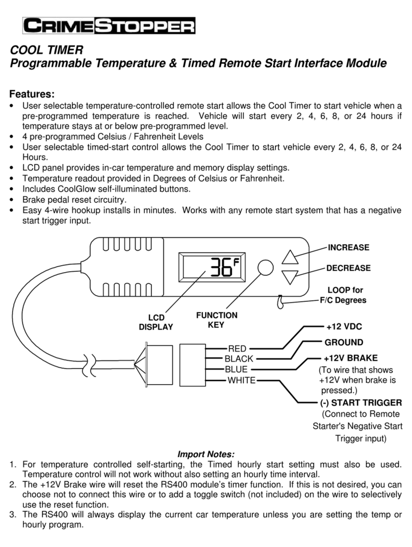
Other CrimeStopper Automobile Accessories manuals

CrimeStopper MIR-DVR User manual

CrimeStopper

CrimeStopper MIR-DVR User manual

CrimeStopper CS-5502 User manual

CrimeStopper

CrimeStopper CS-5502 User manual

CrimeStopper CS-9602PI Quick start guide

CrimeStopper

CrimeStopper CS-9602PI Quick start guide

CrimeStopper CA-504.BRKT User manual

CrimeStopper

CrimeStopper CA-504.BRKT User manual

CrimeStopper CS-870OEM Manual

CrimeStopper

CrimeStopper CS-870OEM Manual

CrimeStopper ST-604.4 User manual

CrimeStopper

CrimeStopper ST-604.4 User manual

CrimeStopper CS-9601PI Quick start guide

CrimeStopper

CrimeStopper CS-9601PI Quick start guide

CrimeStopper MIR-045 User manual

CrimeStopper

CrimeStopper MIR-045 User manual

CrimeStopper SecurView SV-6713 User manual

CrimeStopper

CrimeStopper SecurView SV-6713 User manual

CrimeStopper SV-6930.LM.IR User manual

CrimeStopper

CrimeStopper SV-6930.LM.IR User manual

CrimeStopper ST-202.2 User manual

CrimeStopper

CrimeStopper ST-202.2 User manual

CrimeStopper CS-6604 User manual

CrimeStopper

CrimeStopper CS-6604 User manual

CrimeStopper SV-9145 User manual

CrimeStopper

CrimeStopper SV-9145 User manual

CrimeStopper SV-6920.LM User manual

CrimeStopper

CrimeStopper SV-6920.LM User manual

CrimeStopper PlateCam SV-5200.IR User manual

CrimeStopper

CrimeStopper PlateCam SV-5200.IR User manual

CrimeStopper ST-252.2 Instruction Manual

CrimeStopper

CrimeStopper ST-252.2 Instruction Manual

CrimeStopper CS-9601PI Manual

CrimeStopper

CrimeStopper CS-9601PI Manual

CrimeStopper CS-840RKE User manual

CrimeStopper

CrimeStopper CS-840RKE User manual

CrimeStopper SecurView SV-6911.IR User manual

CrimeStopper

CrimeStopper SecurView SV-6911.IR User manual

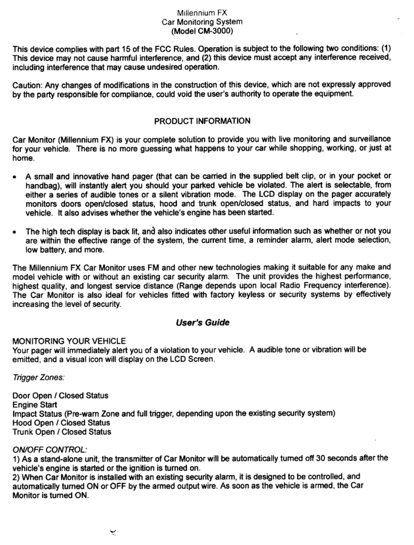
CrimeStopper CM-3000 Millenium FX User manual

CrimeStopper

CrimeStopper CM-3000 Millenium FX User manual

CrimeStopper SV-5500 PC-B User manual

CrimeStopper

CrimeStopper SV-5500 PC-B User manual

CrimeStopper SafetyPlus SV-9153 User manual

CrimeStopper

CrimeStopper SafetyPlus SV-9153 User manual

CrimeStopper SV-6712 User manual

CrimeStopper

CrimeStopper SV-6712 User manual

CrimeStopper CS-5601 User manual

CrimeStopper

CrimeStopper CS-5601 User manual

Popular Automobile Accessories manuals by other brands

VW 1K8 071 609 Fitting instructions

VW

VW 1K8 071 609 Fitting instructions

Ozonics Micro3 reference guide

Ozonics

Ozonics Micro3 reference guide

travall TDG 1534 Fitting instructions

travall

travall TDG 1534 Fitting instructions

Cartizan CHAMPION instruction manual

Cartizan

Cartizan CHAMPION instruction manual

FormFit Tough Guard TG 5D07 installation instructions

FormFit

FormFit Tough Guard TG 5D07 installation instructions

FormFit HDW 5M 05 quick start guide

FormFit

FormFit HDW 5M 05 quick start guide

Rhino-Rack Pioneer Front Rail Kit manual

Rhino-Rack

Rhino-Rack Pioneer Front Rail Kit manual

Thule 316 Roller user manual

Thule

Thule 316 Roller user manual

Pyle PLCMRV8B Black user manual

Pyle

Pyle PLCMRV8B Black user manual

Silverline 874797 manual

Silverline

Silverline 874797 manual

Scosche ITCFDOSB quick start guide

Scosche

Scosche ITCFDOSB quick start guide

Subaru F555EAJ200 installation instructions

Subaru

Subaru F555EAJ200 installation instructions

Carefree MARQUEE Service manual

Carefree

Carefree MARQUEE Service manual

FILTRON K 1165A-2x installation instructions

FILTRON

FILTRON K 1165A-2x installation instructions

Subaru H621SFG500 instructions

Subaru

Subaru H621SFG500 instructions

Safe Fleet Prime Design FBM-1051 Assembly instructions

Safe Fleet

Safe Fleet Prime Design FBM-1051 Assembly instructions

Code 3 XTP Series Installation and operation instructions

Code 3

Code 3 XTP Series Installation and operation instructions

Scania Interlock 700 Series Instructions for use

Scania

Scania Interlock 700 Series Instructions for use

manuals.online logo
manuals.online logoBrands
  • About & Mission
  • Contact us
  • Privacy Policy
  • Terms and Conditions

Copyright 2025 Manuals.Online. All Rights Reserved.