Cumberland Integra Feed-Link User manual

PNEG-1323
Integra Feed-Link
Installation and Operation Manual
PNEG-1323
Date: 05-03-08

2PNEG-1323 Integra Feed-Link
All information, illustrations, photos, and specifications in this manual are based on the latest
information available at the time of publication. The right is reserved to make changes at any
time without notice.

PNEG-1323 Integra Feed-Link 3
Table of Contents
Contents
Chapter 1 Getting Started.................................................................................................................................. 4
Introduction ........................................................................................................................................ 4
Selecting the Load Cell .................................................................................................................... 4
Tools Needed for Installation ............................................................................................................. 4
Chapter 2 Safety................................................................................................................................................. 5
Safety Guidelines .............................................................................................................................. 5
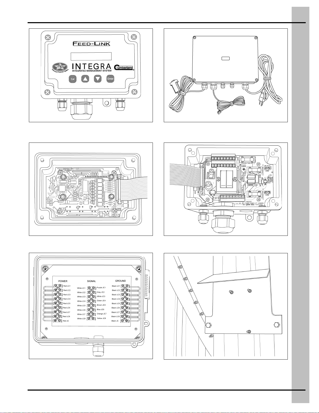
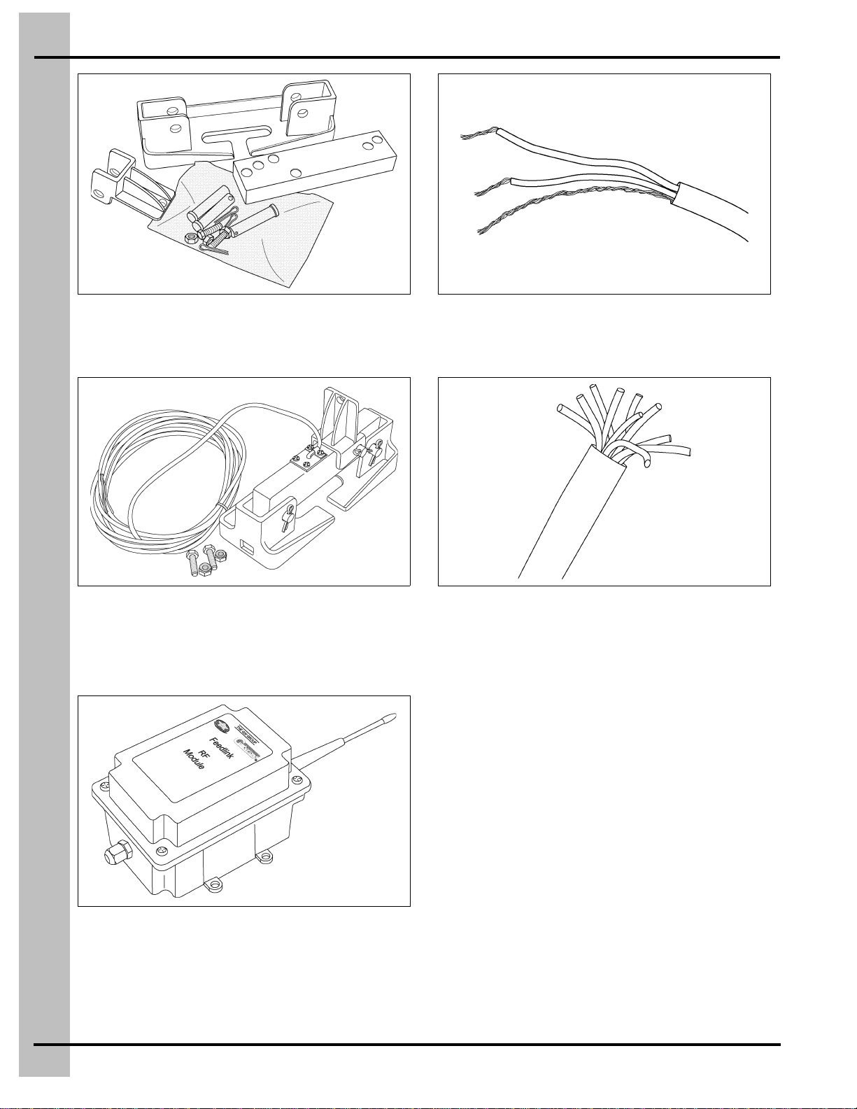
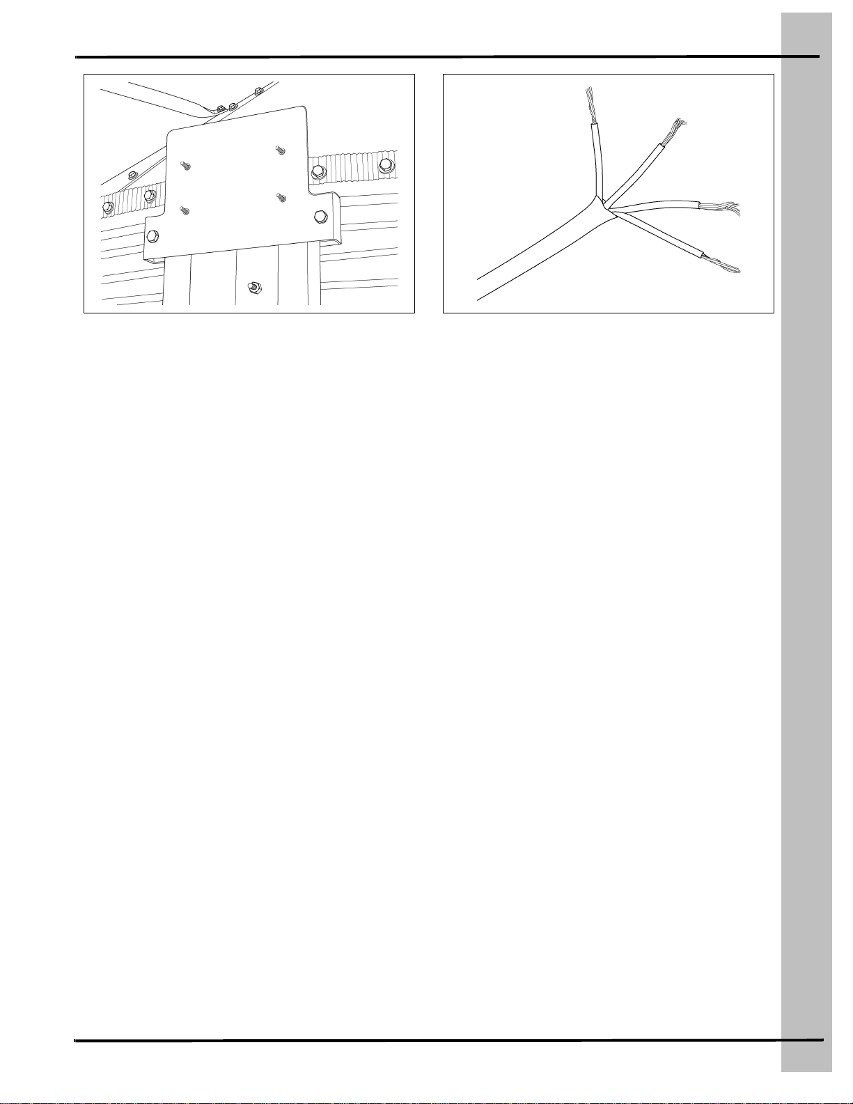
Chapter 3 Part Identification ............................................................................................................................. 7
Chapter 4 Load Cell Installation ..................................................................................................................... 10
Removing Anchor Nuts ................................................................................................................... 10
Raising the Bin ................................................................................................................................ 11
Installing the Load Cell Base ........................................................................................................... 12
Install Load Cell and Attach to Bin Leg ........................................................................................... 13
Installing Load Cell Spacer .............................................................................................................. 14
Running Load Cell Cables ............................................................................................................... 15
Chapter 5 Installing Stand Alone Display Units............................................................................................ 16
Mounting Display and Junction Boxes ............................................................................................ 16
Installing Stand Alone Bin Mounted Display Units .......................................................................... 17
Chapter 6 Stand Alone Remote Mounted Display Units............................................................................... 20
Junction Box .................................................................................................................................... 20
Junction Cable to Inside Mounted Display Unit ............................................................................... 21
Chapter 7 Networking...................................................................................................................................... 22
Explanation of Daisy Chain Network ............................................................................................... 22
Optional Networking Layouts ......................................................................................................... 23
Network Wiring of Display Unit ........................................................................................................ 24
Network Collector Wiring ................................................................................................................. 25
Chapter 8 Water Meter Option ........................................................................................................................ 28
Optional Water Meter ...................................................................................................................... 28
Chapter 9 RF Module Option........................................................................................................................... 29
Mount RF Module to Bin Leg ........................................................................................................... 29
Mount RF Module to Outside of Building ......................................................................................... 30
RF Module Wiring Diagram ............................................................................................................. 31
Possible RF Module Layouts ........................................................................................................... 32
Chapter 10 Display Unit Calibration and Setup............................................................................................. 33
Features ........................................................................................................................................ 33
Display Unit Setup ......................................................................................................................... 34
Troubleshooting Display Unit ........................................................................................................ 37
Chapter 11 Feed-Link Software ...................................................................................................................... 38
Feed-Link Software Installation Instructions ................................................................................. 38
Feed-Link Setup Instructions ......................................................................................................... 38
Chapter 12 Troubleshooting........................................................................................................................... 52
Chapter 13 Warranty........................................................................................................................................ 53

4PNEG-1323 Integra Feed-Link
1. Getting Started
Introduction
READ THIS MANUAL carefully to learn how to properly use and install equipment. Failure to do so could
result in personal injury or equipment damage.
INSPECT the shipment immediately upon arrival. The customer is responsible for ensuring that all
quantities are correct. The customer should report and note any damage or shortage on the bill of lading
to justify their claim to the transport company.
THIS MANUAL SHOULD BE CONSIDERED a permanent part of your equipment and should be easily
accessible when needed.
This warranty provides you the assurance that the company will back its products when defects appear
withinthewarrantyperiod.Insomecircumstances,thecompanyalsoprovidesfieldimprovements,often
without charge to the customer, even if the product isout of warranty. Should the equipment be abused,
or modified to change its performance beyond the factory specifications, the warranty will become void
and field improvements may be denied.
Selecting the Load Cell
Use the proper load cell for the application. Two sizes of load cells are available, a 5000 lbs. per leg load
cell and 10000 lbs. per leg load cell. To determine which load cell to use, add the empty bin weight to
the maximum weight of feed the bin will hold in lbs. Divide this total maximum weight by the number of
legs the bin has. If this number is 5000 lbs. or less, use the 5000 lbs. cell, (INT-4809). If this number is
over 5000 lbs., use the 10000 lbs. load cell (INT-4810). This system cannot be used if the weight is
greater than 10000 lbs.
Tools Needed for Installation
Tools
Tools that can be used during installation may include:
1. Drill
2. Crescent wrench
3. Reciprocating saw
4. Wire cutters
5. Jack lift
6. Impact or ratchet
7. Wire ties
NOTE: Follow all operating and safety guidelines that were provided with the tools.
Empty bin weight (lbs.)
+
Max weight of feed bin will hold (lbs.)
Number of bin legs = Load cell weight

PNEG-1323 Integra Feed-Link 5
2. Safety
Safety Guidelines
This manual contains information that is important for you, the owner/operator, to know and understand.
This information relates to protecting personal safety and preventing equipment problems. It is the
responsibility of the owner/operator to inform anyone operating or working in the area of this equipment
of these safety guidelines. To help you recognize this information, we use the symbols that are defined
below. Please read the manual and pay attention to these sections. Failure to read this manual and its
safety instructions is a misuse of the equipment and may lead to serious injury or death.
This is the safety alert symbol. It is used to alert you to
potential personal injury hazards. Obey all safety
messages that follow this symbol to avoid possible
injury or death.
WARNING indicates a potentially hazardous situation
which, if not avoided, could result in death or serious injury.
CAUTION indicates a potentially hazardous situation which,
if not avoided, may result in minor or moderate injury.
CAUTION used without the safety alert symbol indicates a
potentially hazardous situation which, if not avoided, may
result in property damage.
NOTE indicates information about the equipment that you
should pay special attention.
DANGER indicates an imminently hazardous situation
which, if not avoided, will result in death or serious injury.

6PNEG-1323 Integra Feed-Link
2. Safety
Install and Operate Electrical Equipment Properly
Electrical controls should be installed by a qualified electrician
and must meet the standards set by the National Electrical Code
and all local and state codes.
Disconnect and lock out all power sources before installing
wires/cables or servicing equipment.
Electric Shock Hazard
Prepare for Emergencies
Be prepared if fire starts.
Keep a first aid kit and fire extinguisher handy.
Keep emergency numbers for doctors, ambulance service,
hospital and fire department near your telephone. Keep Emergency Equipment
Quickly Accessible
Wear Protective Clothing
Wear close fitting clothing and safety equipment appropriate
to the job.
Remove all jewelry.
Long hair should be tied up and back.
Safety glasses should be worn at all times to protect eyes
from debris.
Wear gloves to protect your hands from sharp edges on
plastic or steel parts.
Wear steel toe boots to help protect your feet from falling
debris. Tuck in any loose or dangling shoe strings.
A respirator may be needed to prevent breathing potentially
toxic fumes and dust.
Wear hard hat to help protect your head.
Eye Protection
Gloves
Steel Toe Boots
Respirator
Hard Hat

PNEG-1323 Integra Feed-Link 7
3. Part Identification
Figure 3A INT-4807: Display Unit
Figure 3B INT-4813: Display Unit Lid Board
Figure 3C INT-4830 Junction Box
(Includes bin leg mounting bracket)
Figure 3D INT-4808: Network Collector
(Includes Feed-Link Software)
Figure 3E INT-4814: Display Unit Base Board
Figure 3F INT-4812: Bin Leg Mounting Bracket
(for display unit)

8PNEG-1323 Integra Feed-Link
3. Part Identification
Figure 3G INT-4817: Load Cell Spacer
Figure 3H
INT-4809: 5000 lbs. Load Cell
INT-4810: 10000 lbs. Load Cell
Figure 3I INT-4815: RF Module
Figure 3J
INT-4819: 1000' Roll of RS-485 Communication Wire
INT-4820: 500' Roll of RS-485 Communication Wire
Figure 3K
INT-4818-25: 25' of 10 Wire Cable for Junction Boxes
INT-4818-50: 50' of 10 Wire Cable for Junction Boxes
INT-4818-75: 75' of 10 Wire Cable for Junction Boxes
INT-4818-100: 100' of 10 Wire Cable for Junction Boxes

3. Part Identification
PNEG-1323 Integra Feed-Link 9
Figure 3L RF Mounting Bracket Figure 3M
INT-4822-25: 25' of 4 Wire Cable for RF Modules
INT-4822-50: 50' of 4 Wire Cable for RF Modules
INT-4822-75: 75' of 4 Wire Cable for RF Modules
INT-4822-100: 100' of 4 Wire Cable for RF Modules

10 PNEG-1323 Integra Feed-Link
4. Load Cell Installation
Removing Anchor Nuts
1. Use a 3/4" wrench or crescentto remove the
nut and washer from the anchor bolt on the
bin leg. (See Figure 4A.)
2. Remove side bolts using 9/16" wrench and
impact wrench or ratchet.
(See Figure 4B and Figure 4C.)
3. Repeat on all bin legs.
Figure 4A Removing Nut from Anchor Bolt
Figure 4B Remove leg anchor base plate side bolts
using impact wrench and wrench.
Figure 4C All bolts, nuts, and washers removed from
anchor base plate.
Anchor base plate
3/4" Wrench
Side bolts
9/16" wrench
Impact wrench
Anchor base plate
Bin leg

4. Load Cell Installation
PNEG-1323 Integra Feed-Link 11
Raising the Bin
1. Place 4 x 4 spanner board under bin hopper
braces. (See Figure 4D.)
2. Center lift jack under 4 x 4 spanner brace.
(See Figure 4D.)
3. Lift bin with jack about 4".This should lift two
(2) bin legs. (See Figure 4E.)
4. Remove leg anchor base plate.
Figure 4D Jacking Up the Bin
Figure 4E Lift Bin about 4"
Only install load cells on an
empty bin. Lifting a bin with
feed in it can result in damage
to the bin and potential
personal injury.
4 x 4 Spanner board
Jack
Lifted bin leg
Anchor base plate

12 PNEG-1323 Integra Feed-Link
4. Load Cell Installation
Installing the Load Cell Base
1. Shortening the anchor bolt may be required.
It can protrude no more than 1-1/4" above
the foundation. (See Figure 4F.) NOTE: You
may find it easier to put the nut on the bolt
and cut the bolt flush with the nut. This way
the threads are not stripped on the bolt, and
there is not a problem getting the nut on.
2. Position load cell base under bin leg and
around anchor bolt as shown.
(See Figure 4G.)
3. Replace washer and nut onto anchor bolt.
DO NOT tighten fully until assembly is
complete. (See Figure 4H.)
Figure 4F Cut anchor bolt so it sticks up less than
1-1/4" from foundation.
Figure 4G Slide Cell Base Under Leg
Figure 4H Leave anchor bolt loose until assembly
is complete.
Anchor bolt
Reciprocating saw
Bin leg
Load cell base
Load cell base
Wrench

4. Load Cell Installation
PNEG-1323 Integra Feed-Link 13
Install Load Cell and Attach to
Bin Leg
1. Place load cell into load cell base, lining up
the holes. Line up the holes in the side of the
load cell with the holes in the side of the load
cell base.
2. Place pins through the holes and fasten with
a cotter pin. (See Figure 4I.)
3.Attachloadcelltopbrackettotheloadcellby
lining up the holes on the side and fastening
with a pin and cotter pin. Make sure the
tongue on the bracket is on the inside side of
the bin leg.
NOTE: The bin leg should rest on the load cell
bracket. DO NOT drill mounting holes too
high on the leg or the bolts will be
supportingtheweightofthebinratherthan
the load cell bracket.
4. Fasten load cell top bracket to the bin leg
usingbolt,washerandnutthroughthe slot in
the bracket. (See Figure 4J.)
5. Drill a hole into the leg through the top hole
(holeaboveslot)fasteningtolegusingbolts,
washers, and nuts included.
6. Tighten nut on anchor bolt.
Figure 4I Install Load Cell
Figure 4J Drill top hole through bin leg, using top
bracket as a guide.
Load cell
Cotter pins
Pins
Top bracket
Drill bin leg through
top hole of bracket

14 PNEG-1323 Integra Feed-Link
4. Load Cell Installation
Installing Load Cell Spacer
1. The unique patented (Patent #6636820)
field calibration system utilized by Feed-Link
makes it possible to monitor the weight of
feedwithoutrequiringaloadcellunderevery
leg of the bin. This feature allows for the
most economical installation possible. For
monitoring feed consumption, placinga load
cell under every leg will provide maximum
accuracy. If a bin leg does not have a load
cell installed, a load cell spacer will
be needed.
2. To Install a load cell spacer to a bin leg,
follow the same steps as if you were
installing a load cell except substitute the
spacer for the load cell.
3. The same spacer is used for both the
5000 lbs. and 10000 lbs. bins, the
positioning of the spacer will determine if it is
a 5000 lbs. or 10000 lbs. spacer. The
5000 lbs. position will place the spacer
approximately 1/8" below the top of the cell
base. (See Figure 4L.) The 10000 lbs.
position will place the spacer approximately
1/8" above the top of the cell base.
(See Figure 4M.)
4. DO NOT position the spacer as in Figure 4N.
The top load cell bracket is too far from the
cell base and too close to the center of the
spacer, which puts the bin leg out
of alignment.
Figure 4K
Figure 4L Load Cell Spacer Position for 5000 lbs.
Figure 4M Load Cell Spacer Position for 10000 lbs.
Figure 4N Incorrect position of the load cell spacer.
Note how the load cell top bracket is too far from the
load cell base.
Minimum cost Maximum accuracy
Load cells
10000 lbs. Pin placement
5000 lbs. Pin placement
Hole for top bracket
Load cell
spacer
Spacer
Spacer

4. Load Cell Installation
PNEG-1323 Integra Feed-Link 15
Running Load Cell Cables
1. Label both ends of the load cell cable with
the load cell number. Numbers will range
from 1 through 8. Labeling the load cell
cables will identify what terminals to use
when connection wires to display unit
in Installing Stand Alone Display Units on
Page16.Itwillalsoexpeditetroubleshooting
if any problems should arise.
2.Runcablefromload cellupbinlegusingwire
ties (not included) to fasten into place. Run
cable along the cross brace to the center of
thebin. Then take cable around bin boot and
back up the leg that the display or junction
box is mounted to Figure 4O, Figure 4P and
Figure 4Q.
3. Repeat Step 1 and Step 2 for each load cell.
Figure 4O Fasten Wires with Wire Ties
Figure 4P Run wire tie through holes in
bin legs to attach cable to legs.
Figure 4Q Run wires around the boot of the bin.
Wire tie
Wire
Wire tie
Hole in leg
Load
cell
cable
Bin bootCross brace
Wire

16 PNEG-1323 Integra Feed-Link
5. Installing Stand Alone Display Units
Mounting Display and Junction Boxes
The display can be mounted either directly onto
the bin leg or remotely, up to 100' away, such as
inside a nearby building.
When mounted remotely, a junction box must be
used to extend the load cell wires from the bin to
the display unit. The junction box can be mounted
to the bin leg similar to the display shown.
See Figure 5C.
1. Attaching display unit mount to bin leg
a. Take display mount and slide it around
the bin leg. (See Figure 5A.)
b. Attach to leg using 3/8" x 1-1/2" HHCS
bolt and hex nylock nuts. No drilling is
required. (See Figure 5B.)
c. Attach display box to the mount using the
three (3) #10 nuts provided.
2. Attaching junction box to bin leg (Bin leg
mounting bracket is included with
junction box.)
a. Attach junction box and bin leg mounting
bracket to bin leg using 3/8" x 1-1/2"
HHCS bolt and hex nylock nuts. No
drilling is required. (See Figure 5B.)
3. Attaching RF module mount to bin
a. See RF Module Option on Page 29.
Figure 5A Bin Mount Bracket Attached to Bin Leg
Figure 5B Close-up of Bin Mount Bracket on Leg
Figure 5C Display Mounted Outside on Bin Leg
Binmount
bracket
Bin leg
Nut
3/8" x 1-1/2"
HHCS Bolt
Bracket
Bracket
Display
unit

5. Installing Stand Alone Display Units
PNEG-1323 Integra Feed-Link 17
Installing Stand Alone Bin
Mounted Display Units
1. Load cell wires
a. Slide all load cell cables through
grommet cap. (See Figure 5E-A.)
b. Run load cell cables into multi-hole
grommetbyslidingcables throughsliton
side of grommet. (See Figure 5D-A.)
c. Run cables through hole in display box,
giving some extra cable length for
easier installation.
d. To make load cell connections, remove
terminals strips. Insert wires into correct
terminalsandtightenlugs.
(SeeFigure5F
and
Wiring Diagram on Page 18.)
e. Gently pull out any excess length of
cable out through the grommet.
f. Wedge grommet into hole.
(See Figure 5D-B.)
g. Tighten grommet nut cap.
(See Figure 5E-B.)
NOTE: If only three (3) or four (4) holes are used
in the grommet, you need to seal the open
holes using the plugs supplied to make it
water tight. (See Figure 5D-A.)
Figure 5D A) Load cell wire in multi-hole grommet.
B) Grommet wedged into connector.
Figure 5E A) Load cell wires going into display box.
B) Cap tightened onto load cell wires.
Figure 5F Load Cell Connections to Display Box
Always make sure all power is
disconnected and locked out
while display unit cover is OFF.
A
B
Multi-hole grommet
Plug
Multi-hole grommet Connector
B
Load cell wires Power wires
(grommet not included)
Water
meter wires
Grommet cap
Daisy chain “IN” wires
Daisy chain
“OUT” wires
or RF wires
A
Terminal strips
Load cell 3
ground (Black)
Load cell 1 and 2
ground (Black)
Load cell 3
power (Red)
Load cell 1 and
2 power (Red) Load cell 1 signal (White)
Load cell 2
signal (White)

18 PNEG-1323 Integra Feed-Link
5. Installing Stand Alone Display Units
Figure 5G

5. Installing Stand Alone Display Units
PNEG-1323 Integra Feed-Link 19
Installing Stand Alone Bin
Mounted Display Units
(Continued)
2. Set voltage jumpers
a. For 110V line up the two (2) jumpers
with 110V holes.
(See Figure 5H and
Figure 5I-A.)
b. For 220V line up the two (2) jumpers
with 220V holes.
(See Figure 5H and
Figure 5I-B.)
3. Connect power wires
a. Run power wire ends through water tight
heyco nut cap and then into display box
as shown in Figure 5E-A on Page 17.
b.Placelinewire(black)ontoline1,ground
wire (green) onto earth, and neutral wire
(tan or white) onto line 2.
(SeeFigure5J.)
c. Pull excess length of wire down through
water tight heyco nut and tighten.
d. Close display box lid and fasten using
supplied hardware.
Figure 5H Voltage Jumper Location
Figure 5I A) Close-up of 110V Jumper Setting.
B) Close-up of 220V Jumper Setting.
Figure 5J Power Connections
BA
Line 1
(line)
Earth
(ground)
Line 2
(neutral)

20 PNEG-1323 Integra Feed-Link
6. Stand Alone Remote Mounted Display Units
Junction Box
NOTE: If display units are mounted inside, then
you will need a junction box.
1. Remove the multi-hole grommet from the
display unit and exchange it with the
grommet provided with the junction box.
2. Connect the Red wire from load cell 1 to the
POWER terminal labeled RED LC1. Repeat
for each consecutive load cell cable.
ConnecttheREDwire from the10conductor
junction cable to the POWER terminal
labeled RED JC.
3. Connect the
Black
wirefromloadcell 1 to the
GROUND terminal labeled BLACK LC1.
Repeat for each consecutive load cell cable.
Connect the BLACK cable from the 10
conductor junction cable to the GROUND
terminal labeled BLACK JC.
Figure 6A Junction Box Terminals
4. Connect the White wire from load cell 1 to
the left side center SIGNAL terminal labeled
White LC1. Repeat for each consecutive
load cell cable. (See Figure 6B.)
5. Connect the remaining wires (up to 8) from
the 10 wire junction cable to the terminals
opposite the already installed White
SIGNAL load cell wires. Matchthe wire color
to the corresponding terminal labeled with
the same color. Fasten all wires into
terminals using a flat head screw driver.
Then run junction cable from junction box to
thedisplaybox.Junctioncablelengthshould
not exceed 100'.
Figure 6B
Always make sure all power is
disconnected and locked out
while any electrical work is
being performed.
NOTE: Only four (4) load
cell cables shown.
Other manuals for Integra Feed-Link
1
This manual suits for next models
1
Table of contents
Other Cumberland Farm Equipment manuals

Cumberland
Cumberland PNEG-240 User manual

Cumberland
Cumberland Farm Hand Swine Finisher User manual

Cumberland
Cumberland Hi-Lo User manual

Cumberland
Cumberland Integra Feed-Link User manual

Cumberland
Cumberland U-Series User manual

Cumberland
Cumberland FLX-5639 User manual

Cumberland
Cumberland 6500 Series Specification sheet

Cumberland
Cumberland Hi-Lo User manual

Cumberland
Cumberland Hi-Lo Flood Feeder User manual