Z.R. Tools MS25-1 User manual

03/12/2013 Z.R. Tool Inc. (905) 836-0590 - Strapping Machinery, Tools & Parts
www.zrtool.com/html/MS25Manual.htm 1/8
MS25 OPERATION MANUAL
SAFETY INSTRUCTIONS
SPECIFICATIONS
OPERATING INSTRUCTIONS
MAINTENANCE
ADJUSTMENTS
REPLACEMENT OF PARTS
MS25 DIAGRAM
MS25 PARTS LIST
SAFETY INSTRUCTIONS
Please read these instructions carefully. Failure to follow these instructions could result in
severe injury.
1. Before using the tool read the entire operation manual thoroughly.
2. Always wear safety glasses and face protection when operating the tool.
3. Always wear protective gloves when handling strapping.
4. Always use only replacement parts from an authorized dealer.
These tools are designed for use with high tensile strapping and all parts are
manufactured or treated for these extreme conditions. Performance of your tool will be
affected if any other parts are used, which may cause injury.
top of page
SPECIFICATIONS
Model Number Strap Width Strap Thickness
MS25-1 1/2" (13 mm) .020" - .025" (0.5 mm - 0.635 mm)
MS25-2 5/8" (16 mm) .020" - .025" (0.5 mm - 0.635 mm)
MS25-3 3/4" (19 mm) .020" - .025" (0.5 mm - 0.635 mm)
*.015" - .019 (038 mm - 0.48 mm)
requires knife ZR-0070
This tool is not to be used with material above .025" thickness.
Weight: 9.4 lbs (4.25 kg)
Base Length: 4.5" (115 mm)
Base Width: 2.4" (60 mm)
Height: 4.2" (105 mm)
STRAPPING QUALITIES
Designed for use with regular duty strapping (107,000 PSI / 750 N/mm2) to high tensile
strapping (156,000 PSI / 1100 N/mm2).
top of page
OPERATING INSTRUCTIONS
A
Place strapping tightly around the
package and hold in place with left
hand.
Take tool with right hand and pull the
feedwheel lever towards the sealing
lever.
Insert both portions of the strap with

03/12/2013 Z.R. Tool Inc. (905) 836-0590 - Strapping Machinery, Tools & Parts
www.zrtool.com/html/MS25Manual.htm 2/8
Insert both portions of the strap with
left hand into the sealing section.
Release the feedwheel lever and make
certain strapping is held by strap
guide.
B
Hold tool firmly with left hand on the
sealing lever.
With right hand move the tension lever
forward and backward until the desired
tension is obtained.
C
Place right hand firmly on the tension
lever for supporting the tool.
With left hand push the sealing lever
forward until it reaches the stop.
D
Move the sealing lever back to its
original position.
To release the tool, with right hand
pull the feedwheel lever towards the
sealing lever, pushing the lever to the
left away from the sealing section.
top of page
MAINTENANCE
Clean the sealing section regularly with compressed air to remove any dust and particles.
Lubricate daily with a thin grade of oil the die (position 16) and punch (position 26).
This will reduce friction and extend tool as well as part life.
top of page

03/12/2013 Z.R. Tool Inc. (905) 836-0590 - Strapping Machinery, Tools & Parts
www.zrtool.com/html/MS25Manual.htm 3/8
top of page
ADJUSTMENTS
TO ADJUST SEALING DEPTH
Loosen nut (position 33), adjust hexagon socket set screw (position 46) with a hexagon
key, turn counterclockwise to increase sealing depth, or turn clockwise to decrease sealing
depth, re-tigthen nut.
TO ADJUST CLEARANCE BETWEEN THE FEEDWHEEL (POSITION 5) AND GRIPPER
(POSTION 27)
The clearance between the feedwheel and the gripper should be .012" (.31 mm). If the
clearance is more or less than this, it must be adjusted.
To reduce the clearance: loosen nut (position 33A), turn hexagon socket set screw
(position 32) counterclockwise with a ball hexagon key, re-tighten nut.
To increase the clearance: loosen nut (position 33A), turn hexagon socket set screw
(position 32) clockwise with a ball hexagon key, re-tighten nut.
top of page
REPLACEMENT OF PARTS
*Please Note: If you are not familiar with the following replacement procedures, please
contact your authorized dealer for a demonstration or for service.
To Replace The Feedwheel (Position 5)
1. Remove external retaining ring (position 3).
2. Remove tensioning assembly (consisting of tension lever (position 11) and feedwheel
shaft (position 2)).
3. Install new feedwheel with the "O" marking facing the strap guide (position 4), re-
install tensioning assembly observing the key way position during assembly.
4. Re-position strap guide onto the protruding feedwheel shaft.
5. Re-install external retaining ring.
To Replace The Gripper (Position 27)
Note: The gripper is held in a non-adjustable position with spring tension pin (position 28).
1. To remove gripper, use drift pin matching the dimension of the spring tension pin
(position 28) and drive the tension pin into the tool base, until the gripper comes loose
from it's position.
2. Lift feedwheel lever (position 7) to access gripper.
3. Clean cavity area and add one drop of a thin grade of oil in the cavity.
4. To install new gripper, place the gripper into the cavity of the tool base. Re-install the
spring tension pin and drive it into the hole of the tool base, until it is flush with the
tool base.
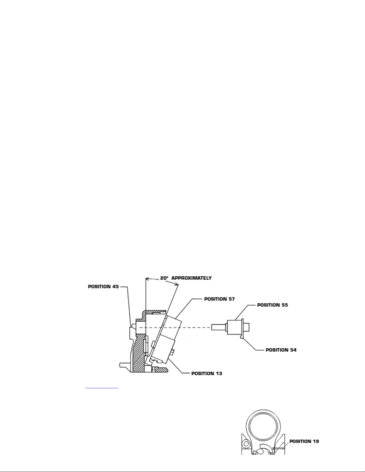
To Replace The Knife (Position 17)
1. Remove housing cover (position 52), by removing 4 hexagon socket shoulder screws
(position 50).
2. With pliers pull knife from slot on die and knife block (position 13).
3. Install new knife observing spring tension pin (position 18) aligns with same slot on die
and knife block.
4. Make sure area is clean and well greased.
5. Re-install housing cover, then re-install hexagon socket shoulder screws with a drop of
Loctite* No. 222 on the thread of each screw.
To Replace The Punch (Position 26)
1. Remove 2 cheese head machine screws (position 24) located on the underside of the
tool base.
2. Remove punch, clean area, replace with new punch, then re-install cheese head

03/12/2013 Z.R. Tool Inc. (905) 836-0590 - Strapping Machinery, Tools & Parts
www.zrtool.com/html/MS25Manual.htm 4/8
2. Remove punch, clean area, replace with new punch, then re-install cheese head
machine screws with a drop of Loctite* No. 222 on each screw.
To Replace The Die (Position 16)
1. Remove housing cover (position 52), by removing 4 hexagon socket shoulder screws
(position 50).
2. Remove sealing lever (position 49), by loosening hexagon socket cap screw (position
48).
3. Remove woodruff key (position 1).
4. Remove eccentric shaft (position 55).
5. Remove the total internal assembly by titling it at a 20 degree angle (see diagram
below) and pull out with pliers by eccentric shaft plunger (position 57), at the same
time making sure to hold internal assembly together with other hand, exposing die on
the underside of the die and knife block (position 13).
6. Remove 2 cheese head machine screws (position 15).
7. Remove die, clean area, and replace with new die, then re-install cheese head
machine screws with a drop of Loctite* No. 222 on each screw.
8. To re-install the internal assembly follow above procedures in reverse order.
9. Re-install the eccentric shaft observing it's relative position to the cam (position 36).
10. The cam lever (position 54) must engage with it's tip into the cavity of the cam. The
components should align together and operate smoothly, please do not force the parts
together.
11. Make sure area is clean and well greased.
12. Re-install housing cover, then re-install hexagon socket shoulder screws with a drop of
Loctite* No. 222 on the thread of each screw.
13. Re-install woodruff key and sealing lever.
*Loctite is a registered trademark of the Loctite Corporation.
Removal of Internal Assembly MS25
top of page
Installation of Internal Assembly MS25
Figure 1A
Place the cam as per drawing, with the long
width sitting flat in the die and knife block.
Add white grease throughout. Then place the
eccentric shaft plunger on top of the cam and
fasten by pushing the connection pin, position

03/12/2013 Z.R. Tool Inc. (905) 836-0590 - Strapping Machinery, Tools & Parts
www.zrtool.com/html/MS25Manual.htm 5/8
19,(making sure the groove on this pin is
facing the outside of the die and knife block)
through hole in die and knife block and into
like hole on eccentric shaft plunger.
Figure 1B
Tilt the internal assembly approximately 20
degrees and place into housing making sure
the back up hook is sitting in its slot in the
housing.
Figure 1C
Make sure the cam lever is attached to the
eccentric shaft. Then push it through the hole
of eccentric shaft plunger and the housing
until it is flush.
Figure 1D
Turn the cam with pliers in a clockwise
direction until it sits in position shown in this
drawing.
Figure 1E
Turn cam lever in a clockwise direction with
fingers until it sits in front of the cavity of the
cam.
Important: Make certain that the roller
(position 59) is in its position.
Then install the housing cover and the sealing
lever making sure they sit properly and
operate smoothly, do not force.
top of page

03/12/2013 Z.R. Tool Inc. (905) 836-0590 - Strapping Machinery, Tools & Parts
www.zrtool.com/html/MS25Manual.htm 6/8
MS25 DIAGRAM
Click here to view larger image
This Diagram is available in a Portable Document Format (PDF) file. To view it, you need to
have Adobe Acrobat Reader version 4.0 installed on your system. Acrobat Reader is
available as a free download from the Adobe Acrobat Reader site.
These documents are fully printable and searchable. For complete information on using
Adobe Acrobat features, including the option of downloading a free copy of Acrobat Reader
4.0, go to the Adobe Acrobat Reader site.
Top of page
MS25 PARTS LIST
Position Part
Number Part Name Parts per Tool
1,1A ZR-0001 Woodruff Key 2
2 ZR-0002 Feedwheel Shaft 1
3 ZR-0003 External Retaining Ring 1
4 ZR-0004 Strap Guide 1/2" (13mm) 1
4 ZR-0005 Strap Guide 5/8" (16 mm) 1
4 ZR-0006 Strap Guide 3/4" (19 mm) 1
5 ZR-0007 Feedwheel 25 1
6 ZR-0008 Roller Bearing 1
7 ZR-0009 Feedwheel Lever 1
8 ZR-0010 Washer 1
9 ZR-0011 Roller Clutch and Bearing Assembly 1
10 ZR-0012 Roller Clutch 1
11 ZR-0013 Tension Lever 1
12 ZR-0014 Handle 2
13 ZR-0015 Die and Knife Block 1
14 ZR-0016 Dowel Pin 2
15 ZR-0017 Cheese Head Machine Screw 2
16 ZR-0018 Die 1/2" (13 mm) 1
16 ZR-0019 Die 5/8", 3/4" (16mm, 19mm) 1
17 ZR-0020 Knife (includes ZR-0021) 1
17 ZR-0070 Knife 15 for strap thickness of .015" - .019"
(0.38 - 0.48mm) only. (includes ZR-0021) 1
18 ZR-0021 Spring Tension Pin 1
19 ZR-0022 Connection Pin 1
20 ZR-0023 Back Up Hook 1
21 ZR-0024 Spring Tension Pin 2

03/12/2013 Z.R. Tool Inc. (905) 836-0590 - Strapping Machinery, Tools & Parts
www.zrtool.com/html/MS25Manual.htm 7/8
21 ZR-0024 Spring Tension Pin 2
22 ZR-0025 External Retaining Ring 2
23 ZR-0026 Shaft 1
24 ZR-0027 Cheese Head Machine Screw 2
25 ZR-0028 Dowel Pin 2
26 ZR-0029 Punch 1/2" (13mm) 1
26 ZR-0030 Punch 5/8", 3/4" (16mm, 19mm) 1
27 ZR-0031 Gripper 1
28 ZR-0032 Spring Tension Pin 1
29 ZR-0033 Cheese Head Machine Screw 2
30 ZR-0034 Spring Tension Pin 2
31 ZR-0035 Strap Stop Front 1/2" (13mm) 1
31 ZR-0036 Strap Stop Front 5/8" (16mm) 1
31 ZR-0037 Strap Stop Front 3/4", 1 1/4" (19mm, 32mm) 1
32 ZR-0038 Hexagon Socket Set Screw 1
33,33A ZR-0039 Nut 2
34 ZR-0040 Extension Spring 1
35 ZR-0041 Hexagon Socket Cap Screw 1
36 ZR-0042 Cam 1
37 ZR-0043 Ball 1
38 ZR-0044 Compression Spring 1
39 ZR-0045 Die Block Back Up 1
40 ZR-0046 Spring Tension Pin 1
41 ZR-0047 Spacer 1
42 ZR-0048 Pin 1
43 ZR-0049 Strap Stop Rear 1/2" (13mm) 1
43 ZR-0050 Strap Stop Rear 5/8" (16mm) 1
43 ZR-0051 Strap Stop Rear 3/4" (19mm) 1
44 ZR-0052 Nut 1
45 ZR-0053 Housing MS25 1
46 ZR-0054 Hexagon Socket Set Screw 1
47 ZR-0055 Roller Bearing 1
48 ZR-0056 Hexagon Socket Cap Screw 1
49 ZR-0057 Sealing Lever 1
50 ZR-0058 Hexagon Socket Shoulder Screw 4
51 ZR-0059 Roller Bearing 1
52 ZR-0060 Housing Cover 1
53 ZR-0061 Cheese Head Machine Screw 2
54 ZR-0078 Cam Lever 1
55 ZR-0063 Eccentric Shaft 1
56 ZR-0064 Roller Bearing 1
57 ZR-0065 Eccentric Shaft Plunger
(includes ZR-0043, ZR-0044, ZR-0064, ZR-0075) 1
58 ZR-0075 Spring Tension Pin 1
59 ZR-0076 Roller 1
60 ZR-0077 Roller Pin 1
-- ZR-0066 Operation Manual and Parts List for MS25 Series
Tools 1
This manual suits for next models
3
Table of contents
Popular Packaging Equipment manuals by other brands

Minipack-Torre
Minipack-Torre Tunnel 50 instruction manual

ITW Mima
ITW Mima Girotec RDL 1800 Service and installation manual

Tepack
Tepack ?4?-12 operating instructions

R.G.V.
R.G.V. 110760 User’s Reference: Use and Maintenance

U-Line
U-Line S-15188 Assembly

ITATOOLS
ITATOOLS ITA18 Operation manual & spare parts list