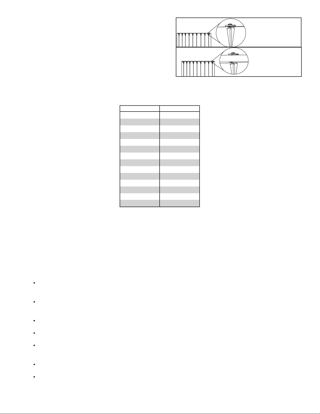
Figure 3.1 - Slide the splice over and tighten.
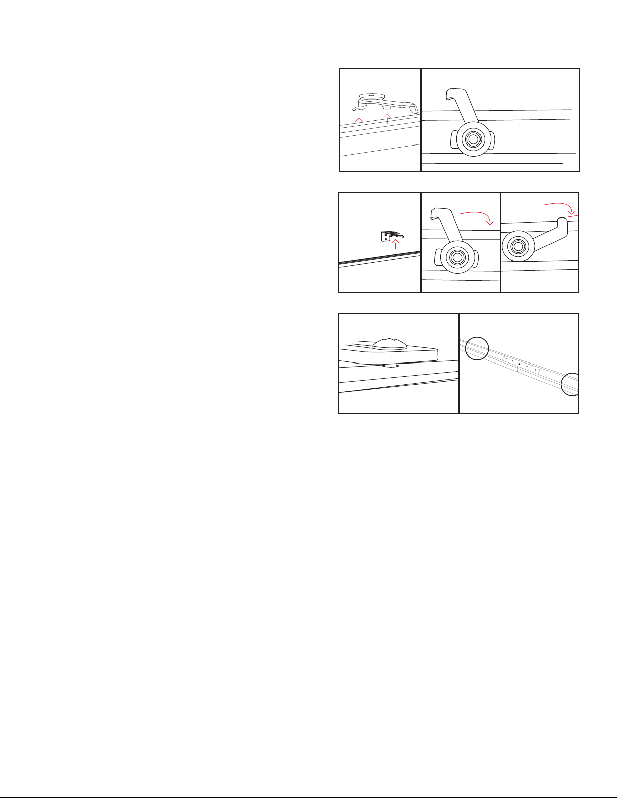
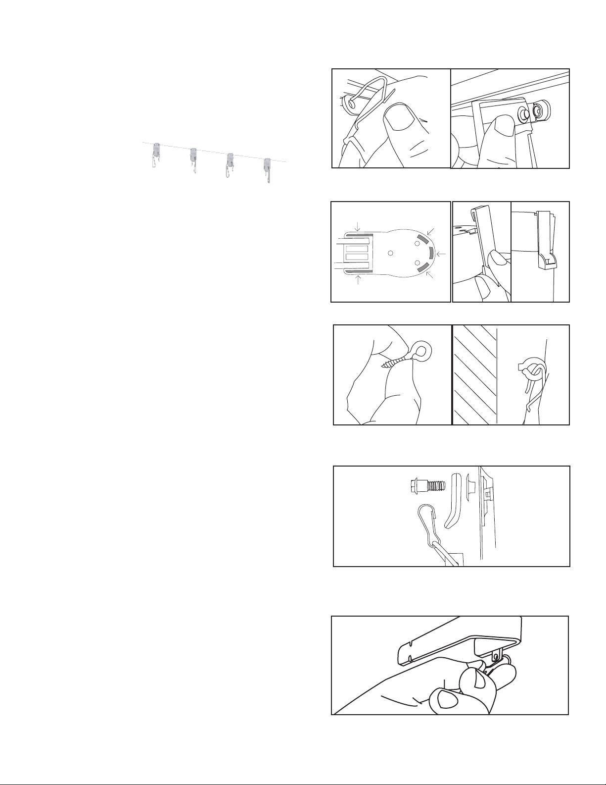
Figure 2.2 - Insert Retaining Plate
I. Splicing the Track
If your track is UNSPLICED, proceed to Section 2: Drapery Track Installation
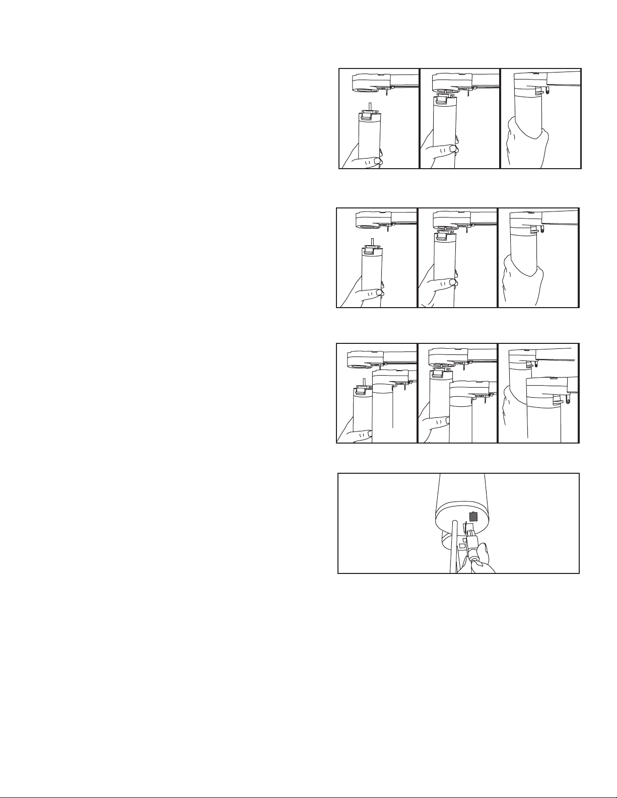
1. Unpack the Track
1.1 - Remove track from plastic and take out the foam block inside
the track that secures the belt.
NOTE: On any spliced track over 12’ in length, be sure to use two or more people to lift the track to prevent bending the splice.
Do not pick up any spliced track upside down or the splice will bend.
1.2 - With the track positioned upside down (carriers pointed up),
apply tension to the belt by gripping both pieces of the
master carrier and pulling them together as you straighten the
track sections. This will help prevent the belt from coming out of
the channels.
2. Install Master Carrier Retaining Plate
2.1 - With the straighten track remaining upside down,
continue moving the master carrier pieces towards each
other while unfolding the track sections.
2.2 - Insert the master carrier retaining plate into both
plastic sections. On center draw applications, do this for both
master carriers.
2.3 - On tracks with string carriers be sure the metal master
carrier retaining plate is oriented correctly to ensure a fit over the
inserted string end.
3. Secure Splice
3.1 - Flip the track on its side, so that the top of the track is
facing towards you. The metal track splice will be inserted into
one side of the track.
3.2 - Loosen the four set screws in the splice using the provided
tool, then slide the splice over the joint where the halves come
together. Maintain good alignment and tighten the four set screws.
Do not over tighten.
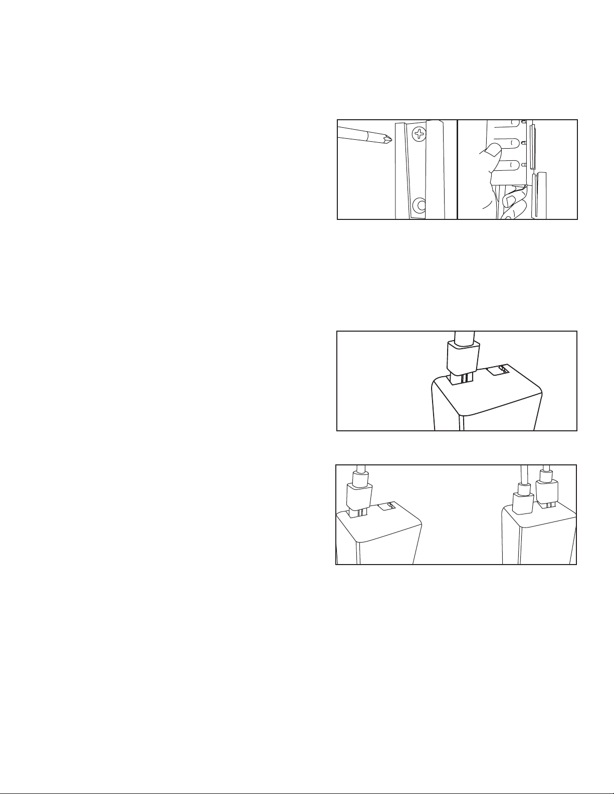
4. Assemble the Master Carrier and Arms
4.1 - Using the diagram inserted with this manual, assemble the master carrier by affixing the wheeled carrier attachment and
carrier arm to the master carrier. Use the provided screws to retain all pieces together.
cOn enter draw applications, be sure to do this for both master carriers.
On side draw applications, be sure the arm is facing the full close direction of the track.
Figure 1.1
Figure 1.2
3