manuals.online logo
Brands
  1. Home
  2. •
  3. Brands
  4. •
  5. CyberData
  6. •
  7. Intercom System
  8. •
  9. CyberData RAL 9003 Manual

CyberData RAL 9003 Manual

Quick Reference 930464B © 2013, CyberData Corporation, ALL RIGHTS RESERVED© 2013, CyberData Corporation, ALL RIGHTS RESERVED 930464B Quick Reference
The IP Endpoint Company
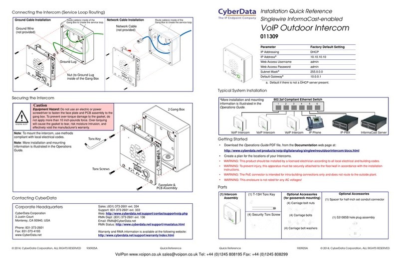
Installation Quick Reference
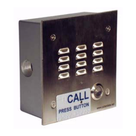
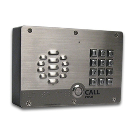
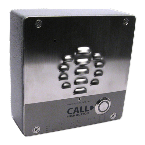
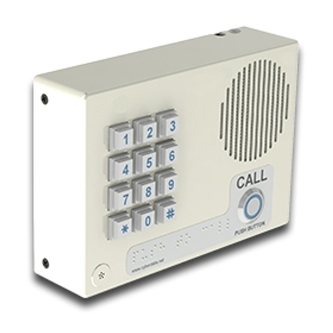
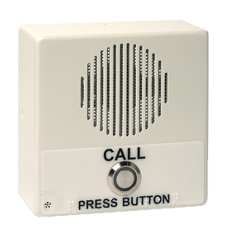
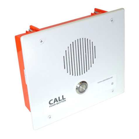
VoIP Remote Call Button
011185, RAL 9003, Signal White
Mounting Options—Metal Bracket
Mounting Options—Plastic Bracket
Contacting CyberData
Mounting
Screw (2x)
Remote
Call Button
Assembly
Wall
Opening
One-Gang
Low Voltage
Mounting Bracket
(Metal)
Gasket
Bend Tabs Up/Down
Against Inside Wall
to Secure Bracket
Wall Plate Mounting Bracket (Metal)
Tools Required: Wall board saw, Pliers
Instructions:
1. Use the inside area of the bracket to trace the hole
cut onto the wall.
2. Using a wall board saw or matt knife, cut along the
stencil line.
3. Place bracket against the wall opening.
4. Bend tabs up and down against the inside wall to
secure the bracket.
5. Place the optional gasket over the metal bracket.
6. Mount the flush mount wall plate to the bracket.
To be installed and or used in accordance with the
appropriate electrical codes and regulations.
Optional
Gasket
Remote Call
Button Assembly
Wall Opening
Bend tabs up and
down against
inside wall to
secure bracket.
One-Gang
Low Voltage
Mounting Bracket
(Metal)
Mounting
Screw (2x)
Mounting
Screw (2x)
Remote
Call Button
Assembly
Wall
Opening
Gasket
Tighten Screws
to Pull WingNuts
Against Inside Wall
to Secure Bracket
One-Gang
Low Voltage
Mounting Bracket
(Plastic)
To be installed and or used in accordance with the
appropriate electrical codes and regulations.
Wall Plate Mounting Bracket (Plastic)
Tools Required: Wall board saw, Philips screwdriver
Instructions:
1. Use the inside area of the bracket to trace the hole
cut onto the wall.
2. Using a wall board saw or matt knife, cut along the
stencil line.
3. Place bracket through the wall opening.
4. Tighten screws to pull Flagnuts against the inside
wall to secure the bracket.
5. Place the optional gasket over the plastic bracket.
6. Mount the flush mount wall plate to the bracket.
Optional
Gasket
Remote Call
Button Assembly
One-Gang
Low Voltage
Mounting Bracket
(Plastic)
Wall Opening
Tighten screws to
pull Flagnuts against
inside wall to secure
bracket.
Mounting
Screw (2x)
Sales: (831) 373-2601 ext. 334
Support: 831-373-2601 ext. 333
Web: http://www.cyberdata.net/support/contactsupportvoip.html
RMA Dept: (831) 373-2601 ext. 136
Email: [email protected]
RMA Status: http://www.cyberdata.net/support/rmastatus.html
Warranty information is available at:
Web: http://www.cyberdata.net/support/warranty/index.html
Corporate Headquarters
CyberData Corporation
3 Justin Court
Monterey, CA 93940, USA
Phone: 831-373-2601
Fax: 831-373-4193
www.CyberData.net
Typical Call Button System Installation
Getting Started
• Create a plan for the locations of your Call Buttons.
• Prior to installation, consult local building and electrical code requirements.
• WARNING: This enclosure is not rated for any AC voltages!
Parts
As an option to the CyberData V2 speaker, the V2 Remote Call Button enables calls to the V2 Speaker that
can be initiated or answered from a remotely-mounted switch.
When enabled through the Web interface, if the Remote Call Button is pressed, the speaker would initiate a
SIP call to a predetermined extension.
When the V2 Speaker is called from a remote phone and Auto-Answer is not enabled within the unit’s Web
interface, the LED on the Remote Button will blink. The call will be answered when the button is pressed.
This document can also be downloaded as a pdf from the following web page:
http://www.cyberdata.net/products/voip/accessories/remotebutton/docs.html
802.3af Compliant Ethernet Switch
IP Phone IP PBX Server
12 34 56
Remote Call Button Speaker
(1) Call Button Assembly
(1) Optional Gasket
(1) Optional One-Gang, Low Voltage,
Mounting Bracket (Metal)
(1) Optional One-Gang, Low Voltage,
Mounting Bracket (Plastic)
(1) Wall Mounting Kit
(2) Mounting screws
Optional Parts (Not Included) (1) Optional One-Gang
Box (Metal)
(1) Optional One-Gang
Box (Plastic)
© 2013, CyberData Corporation, ALL RIGHTS RESERVED 930464B Quick Reference Quick Reference 930464B © 2013, CyberData Corporation, ALL RIGHTS RESERVED
Dimensions
Mounting Options—One-Gang Box (Metal or Plastic)
DIMENSIONS ARE IN INCHES [MILLIMETER]
4.62 [117.5]
2.87 [73.0] SIDE VIEW
1.17 [29.7]
Mounting
Screw (2x)
Remote
Call Button
Assembly
Gasket
Wall
Opening
One-Gang Box
(Metal)
One-Gang Box
(Plastic)
To be installed and or used in accordance with the
appropriate electrical codes and regulations.
Wall Plate Mounting Bracket
One-Gang Box (Metal or Plastic)
Tools Required: Wall board saw
Instructions:
1. Use the outside area of the One-Gang Box to trace
the hole cut onto the wall.
2. Using a wall board saw or matt knife, cut along the
stencil line.
3. Place One-Gang Box through the wall opening.
4. Optional: Nail the One-Gang Box to the stud or
connect it to the set screw connect and conduit.
5. Place the optional gasket over the One-Gang Box.
6. Mount the flush mount wall plate to the One-Gang
Box.
Optional
Gasket
Mounting
Screw (2x)
Remote Call
Button Assembly
One-Gang Box
(Plastic)
Wall Opening
One-Gang Box
(Metal)
Connections
J10 J9
(+12VDC @ 1A)
AUX POWER (-)
RELAY COM
RELAY NO
BUTTON LED (+)
BTN SENSE
AUX SPEAKER (-)
AUX SPEAKER (+)
BTN SENSE GND
LINE OUT (-)
LINE OUT (+)
BUTTON LED (-)
AUX POWER (+)
Back View
VoIP Speaker
Terminal Block

Other manuals for RAL 9003

2

This manual suits for next models

1

Other CyberData Intercom System manuals

CyberData 011311 Manual

CyberData

CyberData 011311 Manual

CyberData #011123 Manual

CyberData

CyberData #011123 Manual

CyberData 011211 series Manual

CyberData

CyberData 011211 series Manual

CyberData 11304 Manual

CyberData

CyberData 11304 Manual

CyberData 011309 Manual

CyberData

CyberData 011309 Manual

CyberData 11214 User manual

CyberData

CyberData 11214 User manual

CyberData VoIP Desktop Intercom Manual

CyberData

CyberData VoIP Desktop Intercom Manual

CyberData 011414 Manual

CyberData

CyberData 011414 Manual

CyberData 11272 User manual

CyberData

CyberData 11272 User manual

CyberData 11304 User manual

CyberData

CyberData 11304 User manual

CyberData 11113 User manual

CyberData

CyberData 11113 User manual

CyberData 011123x User manual

CyberData

CyberData 011123x User manual

CyberData 11113 User manual

CyberData

CyberData 11113 User manual

CyberData 11035 User manual

CyberData

CyberData 11035 User manual

CyberData 11035 User manual

CyberData

CyberData 11035 User manual

CyberData #011123 Manual

CyberData

CyberData #011123 Manual

CyberData 11186 Manual

CyberData

CyberData 11186 Manual

CyberData 11111 User manual

CyberData

CyberData 11111 User manual

CyberData VoIP Intercom 010935F User manual

CyberData

CyberData VoIP Intercom 010935F User manual

CyberData 011530 Manual

CyberData

CyberData 011530 Manual

CyberData 011490 Manual

CyberData

CyberData 011490 Manual

CyberData 11214 User manual

CyberData

CyberData 11214 User manual

CyberData 11305 User manual

CyberData

CyberData 11305 User manual

CyberData #011123 Manual

CyberData

CyberData #011123 Manual

Popular Intercom System manuals by other brands

Matrix COSEC ATOM RD100 Quick installation guide

Matrix

Matrix COSEC ATOM RD100 Quick installation guide

Carus Adapto CAI1100 Product information

Carus

Carus Adapto CAI1100 Product information

urmet domus 1723 Installation handbook

urmet domus

urmet domus 1723 Installation handbook

LAON TECHNOLOGY LT150 MOBILE operating instructions

LAON TECHNOLOGY

LAON TECHNOLOGY LT150 MOBILE operating instructions

Alphatech IP-VarioBell Installation and operating instructions

Alphatech

Alphatech IP-VarioBell Installation and operating instructions

GAINWISE TECHNOLOGY SS1603-08 manual

GAINWISE TECHNOLOGY

GAINWISE TECHNOLOGY SS1603-08 manual

Electra KIT AUDIO DOOR PHONE basic1 family user manual

Electra

Electra KIT AUDIO DOOR PHONE basic1 family user manual

Comelit MAESTRO Series Technical sheet

Comelit

Comelit MAESTRO Series Technical sheet

Aiphone JV-1MD Operation manual

Aiphone

Aiphone JV-1MD Operation manual

LEGRAND D45 SYSTEM installation guide

LEGRAND

LEGRAND D45 SYSTEM installation guide

GVS H Series user manual

GVS

GVS H Series user manual

Commax DRC-40K user manual

Commax

Commax DRC-40K user manual

Look-C H424 Technical manual

Look-C

Look-C H424 Technical manual

CAME PLACO-C installation manual

CAME

CAME PLACO-C installation manual

PSA Panacom PAN920SKHD instruction manual

PSA

PSA Panacom PAN920SKHD instruction manual

Intelligent Home CAT-5 Series Installation and user manual

Intelligent Home

Intelligent Home CAT-5 Series Installation and user manual

Alpha VH30ANC Series Installation and use instructions

Alpha

Alpha VH30ANC Series Installation and use instructions

iCentral M200 user manual

iCentral

iCentral M200 user manual

manuals.online logo
manuals.online logoBrands
  • About & Mission
  • Contact us
  • Privacy Policy
  • Terms and Conditions

Copyright 2025 Manuals.Online. All Rights Reserved.