manuals.online logo
Brands
  1. Home
  2. •
  3. Brands
  4. •
  5. CycleOps
  6. •
  7. Bicycle Accessories
  8. •
  9. CycleOps PowerTap SL User manual

CycleOps PowerTap SL User manual

Other manuals for PowerTap SL

1

Other CycleOps Bicycle Accessories manuals

CycleOps PowerTap SLC+ User manual

CycleOps

CycleOps PowerTap SLC+ User manual

CycleOps PowerTap User manual

CycleOps

CycleOps PowerTap User manual

CycleOps Joule 3.0 User manual

CycleOps

CycleOps Joule 3.0 User manual

CycleOps Joule 2.0 User manual

CycleOps

CycleOps Joule 2.0 User manual

CycleOps Cervo 2.4 User manual

CycleOps

CycleOps Cervo 2.4 User manual

Popular Bicycle Accessories manuals by other brands

Galeo Galeo user guide

Galeo

Galeo Galeo user guide

Shimano DURA-ACE FC-R9100 Dealer's manual

Shimano

Shimano DURA-ACE FC-R9100 Dealer's manual

BAFANG BT C01.340.UART Customer's manual

BAFANG

BAFANG BT C01.340.UART Customer's manual

Minshine T154 Series manual

Minshine

Minshine T154 Series manual

Cateye TRIPLE SHOT PRO HL-EL830RC instruction manual

Cateye

Cateye TRIPLE SHOT PRO HL-EL830RC instruction manual

Navad Trail 200 Quick manual guide

Navad

Navad Trail 200 Quick manual guide

Specialized Elite CylcoComputer user manual

Specialized

Specialized Elite CylcoComputer user manual

Sigma BC 16.16 manual

Sigma

Sigma BC 16.16 manual

Playcore Dero Setbacks installation instructions

Playcore

Playcore Dero Setbacks installation instructions

VDO Cyclecomputing x3dw instruction manual

VDO Cyclecomputing

VDO Cyclecomputing x3dw instruction manual

Cateye RAPID X2 manual

Cateye

Cateye RAPID X2 manual

buratti meccanica Clorofilla Trail Use and maintenance manual

buratti meccanica

buratti meccanica Clorofilla Trail Use and maintenance manual

Shimano SG-8R20 Service instructions

Shimano

Shimano SG-8R20 Service instructions

BOB YAK owner's manual

BOB

BOB YAK owner's manual

APLIC 303303/20190717TW012 user manual

APLIC

APLIC 303303/20190717TW012 user manual

Polini HI-SPEED E-BIKE quick start guide

Polini

Polini HI-SPEED E-BIKE quick start guide

SRAM AXS BlipBox user manual

SRAM

SRAM AXS BlipBox user manual

Shimano FD-RX810 Dealer's manual

Shimano

Shimano FD-RX810 Dealer's manual

manuals.online logo
manuals.online logoBrands
  • About & Mission
  • Contact us
  • Privacy Policy
  • Terms and Conditions

Copyright 2025 Manuals.Online. All Rights Reserved.

PowerTap SL
OWNER’S MANUAL
2
CCooppyyrriigghhtt
Copyright 2003. All rights reserved. No part of this publication may be copied, photographed,
reproduced, translated, transmitted electronically or placed on digital media without the prior
written consent of Saris Cycling Group,Inc.
TTrraaddeemmaarrkkss
Saris Cycling Group,Inc , PowerTap and the PowerTap logo, are all registered trademarks of Saris
CyclingGroup,Inc.Allotherproduct,brand,ortradenamesusedinthismanualmaybetrademarks
or registered trademarks of their respective owners.
MMooddiiffiiccaattiioonnss
Saris Cycling Group,Inc reserves the right to make improvements and/or updates to the products
described herein at any time without notice.
Saris Cycling Group,Inc.
5253Verona Road
Madison,WI USA
www.cycleops.com
1-800-783-7257
16034 A 12/04
Patents Issued and Pending
Patent #6,418,797
3
CCOONNTTEENNTTSS
Introduction
System Overview
Wheel Building
System Installation
PowerTap SL Receiver Installation
PowerTap SL General Operation
PowerTap SL Computer Navigation
PowerTap SL Interval Mode
PowerTap SL Computer Set Up
Maintenance &Specifications
Hub Batteries/O-ring Replacement
Test Mode
Trouble Shooting
Warranty andTechnical Support
4
5
6
7
9
11
12
14
15
23
27
28
30
38
4
IINNTTRROODDUUCCTTIIOONN&&PPRREECCAAUUTTIIOONNSS
Thank you for your purchase of the CycleOps PowerTapTM . Power is the ultimate measure of
performance.No other equipment will give you greater return on your investment.For more
information regarding training with power,please go to ourWeb site at www.cycleops.com
PPRREECCAAUUTTIIOONNSS::IIMMPPOORRTTAANNTT
1.Beforebeginning anytraining program,alwayscheck with yourphysician.
2.KKeeeeppyyoouurreeyyeessoonntthheerrooaadd.Do not become overly engaged with the PowerTap display.We recom-
mendfamiliarizing yourself with computerfunctionswhile stationary.
3.Thecomputer,receiver,andhubarewaterresistant.However,avoidextendedsubmersionorhigh-pres-
surespraysdirectedat PowerTapcomponents.
4.Washoffdirtwithamilddetergentonasoftcloth.Wipeexcesswateroffwithadrycloth.Donotapply
kerosene,paintthinner,alcohol,benzine or othersuch solventsto any PowerTapcomponents.
5.The plastic cover on the hub should be removed only when replacing batteries,or when allowing the
unit to dry after submersion in water. Repeated disassembly may compromise the effectiveness of the
O-ring seals. O-rings should be inspected and replaced if necessary whenever the battery cover is
removed.Use alightcoating of greasewhen reinstallingthebatterycap ontheO-rings.
6.ThePowerTapwheel doesnot include aquick release skewer.CycleOps recommendsusing a
steelskewer.
7.Both sides of the PowerTap should be built using a 3x spoke lacing pattern.Because of the design of
thePowerTap,torqueis transmittedthrough the hubtothe non-drive side.
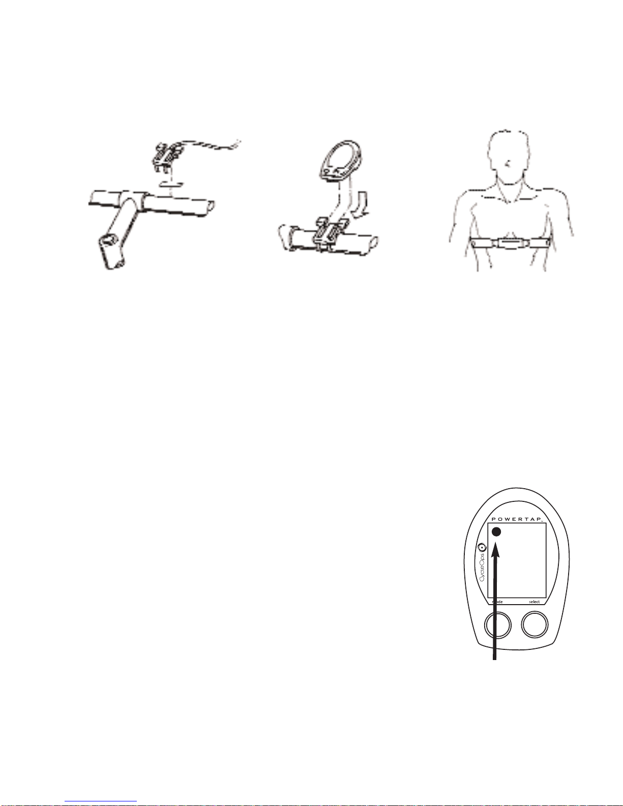
8.Electromagneticinterference,suchas interferencecaused byhigh powerlines,maybriefly disruptthe
communicationbetweenthe hub,cheststrap andcomputer.
9.The PowerTap is available only in a 130 & 135mm range of axle lengths to accommodate different
frames and uses.Only use similarly sized frames and hubs. FFaaiilluurreettooaaddhheerreettootthheesseepprreeccaauuttiioonnssmmaayy
ccaauusseepprreemmaattuurreeffaaiilluurreeoorriinnccoorrrreeccttooppeerraattiioonnoofftthheeuunniittaannddmmaayyvvooiiddtthheewwaarrrraannttyy..
10. PleaseregisteryourPowerTapat www.cycleops.com.
5
SSYYSSTTEEMMOOVVEERRVVIIEEWW
TThheePPoowweerrTTaappSSyysstteemm
The PowerTap system includes a power-measuring hub which measures torque and wheel
speed. This information is then transmitted via digital radio frequency to a receiver mounted on
the seat stay. The data is wired to the PowerTap computer mounted on the handlebar. The com-
puter receives the signal from the heart rate monitor chest strap to provide heart rate information.
All of this information is then processed for display on the computer.
PPrreeppaarriinnggffoorrIInnssttaallllaattiioonn
The PowerTap hub comes either in a pre-built wheel or alone, ready to build into a wheel. The
power measuring hub must be built into a complete wheel prior to installation. Other items nec-
essary for installation are a cassette, spoke protector, reflectors, skewer, rim strip, tire, and tube
(clincher rim) or glue and tubular tire (tubular rim). Please read all instructions prior to installation.
Also take a moment to verify the package contents. The installation procedure with a complete
wheel requires only a trimmer to clip the cable ties. However, assembling the wheel, cassette and
other parts requires the proper tools and experience. If you are unsure of any step of the proce-
dure or do not have all of the tools necessary for installation, contact your local dealer
for assistance.
1 PowerTap hub (or built wheel)
1 PowerTap computer
1 Receiver
1 Chest strap
4 Foam mounting tapes
12 Cable ties
1 Training With Power guide by CTS
1 Product registration card
1 PowerLink Lite CD
1 Link cable
1 Cadence Magnet (Pro Model Only)
10 Cadence Sensor Cable Ties
1 Extra CPU Battery
Qty Item
PPaacckkaaggeeCCoonntteennttss
Measurements Drive Non-Drive
Hub center to flange 17.4mm 31.7mm
Flange Diameter 70mm 70mm
Spoke hole diameter: 2.5mm
WWhheeeellBBuuiillddiinnggDDiimmeennssiioonnss
6
SSYYSSTTEEMMOOVVEERRVVIIEEWW
CCoommppaattiibbiilliittyy
The PowerTap SL hub is compatible with Shimano 8, 9, and 10 speed systems or
Campagnolo 8, 9, and 10 speed. Free hub bodies may be interchanged. See page 24 for
instructions.
Only insert the correctly spaced PowerTap hub into your frame.
For example, only use a 130mm-spaced hub in a 130mm road frame. Do not force the hub
into any frame. Doing so may cause failure of the frame, hub, or both, and will void the
warranty. Contact your dealer or PowerTap to address any special compatibility issues.
WWHHEEEELLBBUUIILLDDIINNGG
Contact your local wheel building professional or dealer for assistance in building the PowerTap
hub if not provided as a complete wheel. The flanges are drilled for 14 or 15 gauge spokes. Use
at least a two-cross pattern on both sides of the hub. Due to the design of the hub, the load path
is not the same as with a conventional hub. Slotting the hub flanges to accommodate bladed
spokes is not recommended and will void the warranty.
RReeffeerreenncceeaassppookkee--lleennggtthhccaallccuullaattoorrwwhheennbbuuiillddiinnggaawwhheeeell..
7
Mount the bottom of the
receiver a maximum of
3 inches from the axle
SSYYSSTTEEMMIINNSSTTAALLLLAATTIIOONN
11..IInnsseerrttWWhheeeellIInnttooFFrraammee
Insert thecomplete builtPowerTap wheelinto the frame.Make sure theaxle iscorrectlypositioned
in the dropouts and secure wheel in place with a steel skewer.
22..AAttttaacchhRReecceeiivveerrTTooSSeeaattSSttaayy
Place foam tape between the receiver and frame for
a slip-free fit. If necessary, rotate receiver to within 5
degrees of parallel with the hub battery cover before
tightening cable ties. Mount receiver a maximum of 3
inches from the axle.
Receiver Standard Pro SL
7 inch Compatible Compatible Compatible
3-5 inch Compatible Compatible Incompatible
Max 3 inch Compatible Compatible Compatible
RReecceeiivveerrCCoommppaattiibbiilliittyyCChhaarrtt
Mount receiver within 5
degrees of parallel with
the hub battery cover.
SSYYSSTTEEMMIINNSSTTAALLLLAATTIIOONN
8
Figure3:Mounting ofcomputer shoe
33..AAttttaacchhCCoommppuutteerrMMoouunnttttooHHaannddlleebbaarr
The computer mounts to the handlebar in a similar fashion. Position the foam mounting tape
beneath the mount and secure with cable ties to handlebar. The head of the cable tie fits flush
into a recessed cavity on the mount.
44..PPllaacceeCCoommppuutteerr
Place the computer into the mounting shoe on the handlebar. Line up the slots on the base of the
computer with the bracket. Slide completely into computer mount.
(see figure 4)
55..HHeeaarrttRRaatteeMMoonniittoorrSSttrraapp
Position the heart rate monitor strap on your torso as pictured in figure 6.
Thestrap shouldrestjustbeneath thepectoral musclesof the chest.Make
sure the electrodes on the strap are slightly moist where it contacts the
skin for best results. The heart rate strap must be worn to enable the heart
rate functionality of the PowerTap.
(see figure 5)
The chest strap is not
coded.
66..VVeerriiffyyIInnssttaallllaattiioonn
Check all the components to make sure they are securely attached.
Spin the rear wheel and verify that the transmission icon on the computer
display is illuminated. This indicates that the hub is sending a valid signal
through the receiver to the cpu. (see figure 6). Adjust the receiver
if necessary.
Figure4:Attaching ofcomputer Figure5:Placementofheartratestrap
Figure6:Transmissioniconin
upperleft cornerofdisplay
9
CCaaddeennccee
WWiirree
PPoowweerrTTaappPPrrooCCaaddeenncceeWWiirree
-Attach cadence magnet to crank arm so
the center of the magnet passes the wired
end of the sensor unit. Do not center the
magnet in relation to the sensor.
PPOOWWEERRTTAAPPSSLLRREECCEEIIVVEERRIINNSSTTAALLLLAATTIIOONN
10
1sec. 2 sec. 5 sec. 10 sec. 30 sec.
Black 3.5 7 NA NA NA
Yellow 1 7.5 15 30 60 180
Yellow 2 15 30 60 120 360
43,690 data points available
Black CPU Yellow 1 CPU Yellow 2 CPU
PowerTap Recording Rates
PowerTap Models