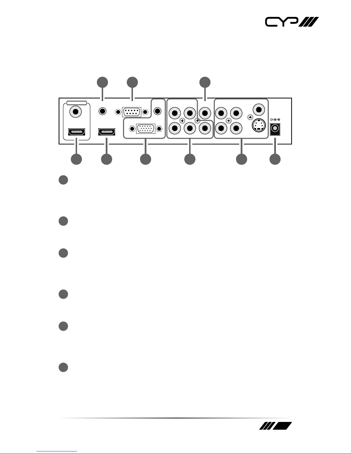
CYP CP-255I User manual

CP-255I
Analogue to HDMI Scaler / Converter
OPERATION MANUAL


3
DISCLAIMERS
The information in this manual has been carefully checked and is
believed to be accurate. CYP (UK) Ltd assumes no responsibility for any
infringements of patents or other rights of third parties which may result
from its use.
CYP (UK) Ltd assumes no responsibility for any inaccuracies that may be
contained in this document. CYP (UK) Ltd also makes no commitment to
update or to keep current the information contained in this document.
CYP (UK) Ltd reserves the right to make improvements to this document
and/or product at any time and without notice.
COPYRIGHT NOTICE
No part of this document may be reproduced, transmitted, transcribed,
stored in a retrieval system, or any of its part translated into any language
or computer le, in any form or by any means—electronic, mechanical,
magnetic, optical, chemical, manual, or otherwise—without express
written permission and consent from CYP (UK) Ltd.
© Copyright 2011 by CYP (UK) Ltd.
All Rights Reserved.
Version 1.1 August 2011
TRADEMARK ACKNOWLEDGMENTS
All products or service names mentioned in this document may be
trademarks of the companies with which they are associated.

4
SAFETY PRECAUTIONS
Please read all instructions before attempting to unpack, install or operate
this equipment and before connecting the power supply.
Please keep the following in mind as you unpack and install this
equipment:
• Always follow basic safety precautions to reduce the risk of re,
electrical shock and injury to persons.
• To prevent re or shock hazard, do not expose the unit to rain,
moisture or install this product near water.
• Never spill liquid of any kind on or into this product.
• Never push an object of any kind into this product through any
openings or empty slots in the unit, as you may damage parts inside
the unit.
• Do not attach the power supply cabling to building surfaces.
• Use only the supplied power supply unit (PSU). Do not use the PSU if
it is damaged.
• Do not allow anything to rest on the power cabling or allow any
weight to be placed upon it or any person walk on it.
• To protect the unit from overheating, do not block any vents or
openings in the unit housing that provide ventilation and allow for
sucient space for air to circulate around the unit.
REVISION HISTORY
VERSION NO. DATE SUMMARY OF CHANGE
v1.01 21/10/13 First release

5
CONTENTS
1. Introduction...........................................6
2. Applications ...........................................6
3. Package Contents ..................................6
4. System Requirements ...........................6
5. Features..................................................7
6. Operation Controls and Functions.......8
6.1 Front Panel................................................... 8
6.2 Rear Panel..................................................... 9
6.3 OSD Operation .........................................11
6.4. Remote Control.......................................12
7. RS-232 Remote Control Protocol....... 13
7.1 Pins denition of modem cable.........13
7.2 Set Command:..........................................14
7.3 Status Command.....................................16
8. Connection Diagram .......................... 17
9. Specications...................................... 18
9.1. General Specication............................18
9.2. Supported Resolutions.........................19

6
1. INTRODUCTION
Cypress's CP-255I Scaler Box is designed to upscale digital/analog
video signals from Composite, S-Video, PC, Component (HD) and HDMI
input sources, to digital HDMI output of a wide range of HDTV and PC
resolutions including 1080p and WUXGA (1920 x 1200).
Aswell as upscaling video, the scaler box also converts digital/analog
audio signals to digital format, which can then be output either through
HDMI combined with the video signal or separately via the discrete
Coaxial S/PDIF output.
Cypress CP-255I has a comprehensive on-screen display (OSD) menu that
allows the user to select a variety of output resolutions and adjust them
for the best picture quality.
2. APPLICATIONS
Upscale the video from standard denition sources or a PC/Laptop to a
HDMI equipped display
3. PACKAGE CONTENTS
Cypress CP-255I Scaler Box
D-Sub (15pin) Cable
3 × RCA Cable (Composite Video and Stereo Audio)
Remote Controller
5V DC Power Supply Adaptor
Operation Manual
4. SYSTEM REQUIREMENTS
INPUT: Composite, Component, S-Video or HDMI, or PC VGA video/
audio source.
OUTPUT: HDMI equipped TV or monitor, optional Coaxial (S/PDIF)
equipped receiver/amplier.

7
5. FEATURES
HDMI, HDCP 1.1 and DVI 1.0 compliant.
Scales any PC (VGA~WUXGA) or HD (480i~1080p) resolutions to from
another PC/HD resolutions.
Automatically detects the correct settings of the connected display
and outputs the corresponding resolution and refresh rate, when the
NATIVE output is selected.
Supports 50/60 Hz frame rate conversion.
Supports 3D motion video adaptive, 3D de-interlacing, and 3:2 / 2:2
pull-down detection and recovery.
Provides output picture adjustment on contrast, brightness, hue,
saturation, sharpness, RGB (color tone) level, and aspect ratio size.
Supports high resolution input/output:
PC: VGA, SVGA, XGA, SXGA, UXGA, WXGA, WSXGA, WUXGA
HDTV: 480i, 576i, 480p, 576p, 720p, 1080i and 1080p
Supports digital and analog audio input and digital output.

8
6. OPERATION CONTROLS AND FUNCTIONS
6.1 Front Panel
POWER CV SV COMP PC
MENU ENTER
Digital Video Scaler Processor
-
+
HDMI
21 3 4 5 6
1
POWER Button and LED Indicator
Press the button power the unit on or o. When the power is turned
on, the LED will illuminate.
2
IR remote control sensor
3
Input Selection Buttons and LED Indicators
Press the required button (CV/SV/COMP/PC/HDMI) to select
the desired input source. The LED will illuminate to indicate the
corresponding input is selected.
4
MENU Button
Press the MENU button to bring up OSD operation menu (see section
4.3 OSD Operation for reference.)
5
+/− Buttons
A. On the rst level of OSD menu, use + and − buttons to move up/
down the menu to highlight the item for selection.
B. Once the desired option is selected, use + and − buttons to toggle
between setting values.
6
ENTER Button
In the OSD menu, use the ENTER button to conrm the selection.

9
6.2 Rear Panel
HDMI OUT
AUX IN RS-232 PC IN
HDMI IN
PC IN
R
Cr/Pr
L
Cb/Pb
CO-AX
Y
R
R
LCV
DC 5V
LSV
CO-AX OUT
31 5 6 8
742
9
1
HDMI OUT and CO-AX OUT
Connect the HDMI OUT port to the HDMI input port of your display
such as HDTV or monitor. Connect the CO-AX OUT port to the Coaxial
(S/PDIF) input port of your amplier for separate digital audio output.
2
AUX IN Input
When the video signal input through the HDMI IN port is from a DVI
source such as a PC, use the AUX IN port to input the audio signal.
3
HDMI IN Input
Connect the HDMI IN port to the HDMI output port of your source
equipment such as a DVD player or Set-top box. You can also use a
HDMI to DVI cable to connect to the DVI output of your PC.
4
RS-232
The port is for rmware update and RS-232 control (refer to section 7.2
for RS-232 commands).
5
PC IN for Video and Audio Input
Connect the PC IN D-Sub (15-pin) port to the D-Sub output port of
your PC and connect the PC IN 3.5mm phone jack to the audio output
port of your PC.
6
Y Pb/Cb Pr/Cr Video and L/R Audio Input
Connect the Y Pb/Cb Pr/Cr (Component) 3 RCA input ports to the
Component output port of your video source equipment such as a
DVD player or Set-top box and connect the L/R audio input ports to
the audio output port of your audio source equipment.

10
7
CO-AX Input
The CO-AX port provides the digital audio input support, and can be
assigned to any of the video inputs (CV/SV/COMP/PC/HDMI). Once
connected, it can be assigned in the OSD Menu under Audio Source
Selection by selecting between Coaxial (S/PDIF) or other audio source
(see section 4.3 OSD Operation for reference).
8
Composite Video / S-Video and L/R Audio Input
Connect the Composite or S-Video input port to the Composite or
S-Video output port of your video source equipment such as DVD
player or Set-top box and connect the L/R audio input ports to the
audio output port of your audio source equipment.
9
Power
Plug the 5V DC power supply into the unit and connect the adaptor to
AC wall outlet.

11
6.3 OSD Operation
1ST MENU
LEVEL 2ND MENU LEVEL ADJUSTMENT
VIDEO - PICTURE MODE USER / STANDARD / VIVID / MOVIE
- CONTRAST 0~100 of Contrast Level
- BRIGHTNESS 0~100 of Brightness Level
- HUE 0~100 of Hue Level
- SATURATION 0~100 of Saturation Level
- SHARPNESS 0~100 of Sharpness Level
- SCALE OVERSCAN/UNDERSCAN/LETTERBOX/
PANSCAN/FULL
- NR LOW/MIDDLE/HIGH/OFF
- EXIT Back to the 1st Menu Level
COLOR - COLOR TONE USER/NORMAL/WARM/COOL
- RED 0~100 of Red Color Level
- GREEN 0~100 of Green Color Level
- BLUE 0~100 of Blue Color Level
- EXIT Back to the 1st Menu Level
OUTPUT - NATIVE, VGA, SVGA, XGA, SXGA, UXGA,
480i, 480p, 720p@60 Hz, 1080i@30 Hz,
1080p@60 Hz, 576i, 576p, 720p@50 Hz,
1080i@25 Hz, 1080p@50Hz, WXGA, WSXGA,
WUXGA
OSD - HPOSITION 0~100 of OSD Horizontal Position
- VPOSITION 0~100 of OSD Vertical Position
- TIMER 0~100 of OSD Show Time (sec)
- TRANSP 0 ~ 100 of OSD Transparent Level
- EXIT Back to the 1st Menu Level
AUDIO - SOURCE HDMI / L/R / COAXIAL
- DELAY OFF / 40 ms / 110ms / 150ms
- SOUND ON/MUTE
- EXIT Back to the 1st Menu Level
INFORMATION - SOURCE (Input interface)
INPUT (Input resolution)
OUTPUT (Output resolution)
VERSION (Firmware version)
EXIT - Close the OSD Menu

12
6.4. Remote Control
1. POWER:
Press the button once to power on the unit. Press
again to enter standby mode.
2. INPUT:
Press the button repeatedly to toggle through
various input sources.
3. HD INPUT:
Press the button to directly select component
input.
4. PC INPUT:
Press the button to directly select PC input.
5. HDMI/DVI INPUT:
Press the button to directly select DVI (or HDMI) input.
6. OUTPUT RESOLUTION:
Press appropriate button to directly select the preferred output resolution.
Other output resolutions that are not covered by these buttons can be
selected from the OSD Menu.
7. MENU:
Press the button to bring up the OSD main menu page.
8. EXIT:
Press the button to exit from a sub menu or main menu.
9. UP/DOWN/LEFT/RIGHT:
Press the Up/Down button to move the highlight bar to your desired
parameter during the OSD operation. Press the Left/Right button to
increase/decrease the value of a selected parameter.
10. OK ENTER:
Press the button to conrm your selection.
11. RESET:
Press the button to reset the unit's rmware setting to the factory default
value.
12. AUTO ADJUST:
Press the button to optimize the positioning of the picture (picture
centering) on the screen.
2
6
8
11 12
9
7
5
4
1
10
3

13
7. RS232 REMOTE CONTROL PROTOCOL
7.1 Pins denition of modem cable
The connection between the unit and remote controller with
RS-232 modem cable*.
UNIT REMOTE CONTROLLER
PIN DEFINITION
PIN DEFINITION
1 NC 1 NC
2 TXD 2 RXD
3 RXD 3 TXD
4 NC 4 NC
5 GND 5 GND
6 NC 6 NC
7 NC 7 NC
8 NC 8 NC
9 NC 9 NC
*RS-232 transmission format:
Baud Rate: 19200 bps
Data Bit: 8-bits
Parity: None
Stop Bit: 1-bit

7.2 Set Command:
COMMAND CODE RESPONSE DESCRIPTION
S POWER 0 > POWER OFF POWER OFF
S POWER 1 > POWER ON POWER ON
S SOURCE 0 > SOURCE CV CV INPUT
S SOURCE 1 > SOURCE SV SV INPUT
S SOURCE 2 > SOURCE COMP COMP INPUT
S SOURCE 3 > SOURCE PC PC INPUT
S SOURCE 4 > SOURCE HDMI HDMI INPUT
S OUTPUT 0 > OUTPUT NATIVE NATIVE RESOLUTION OUTPUT
S OUTPUT 1 > OUTPUT VGA VGA RESOLUTION OUTPUT
S OUTPUT 2 > OUTPUT SVGA SVGA RESOLUTION OUTPUT
S OUTPUT 3 > OUTPUT XGA XGA RESOLUTION OUTPUT
S OUTPUT 4 > OUTPUT SXGA SXGA RESOLUTION OUTPUT
S OUTPUT 5 > OUTPUT UXGA UXGA RESOLUTION OUTPUT
S OUTPUT 6 > OUTPUT 480I 480I RESOLUTION OUTPUT
S OUTPUT 7 > OUTPUT 480P 480P RESOLUTION OUTPUT
S OUTPUT 8 > OUTPUT 720P 720P 60HZ RESOLUTION OUTPUT
S OUTPUT 9 > OUTPUT 1080I 1080I 60HZ RESOLUTION OUTPUT
S OUTPUT 10 > OUTPUT 1080P 1080P 60HZ RESOLUTION OUTPUT
S OUTPUT 11 > OUTPUT 576I 576I 60HZ RESOLUTION OUTPUT
S OUTPUT 12 > OUTPUT 576P 576P 60HZ RESOLUTION OUTPUT
S OUTPUT 13 > OUTPUT 720P 720P 50HZ RESOLUTION OUTPUT
S OUTPUT 14 > OUTPUT 1080I50 1080I 50HZ RESOLUTION OUTPUT
S OUTPUT 15 > OUTPUT 1080P50 1080P 50HZ RESOLUTION OUTPUT
S OUTPUT 16 > OUTPUT WXGA WXGA RESOLUTION OUTPUT
S OUTPUT 17 > OUTPUT WSXGA WSXGA RESOLUTION OUTPUT
S OUTPUT 18 > OUTPUT WUXGA WUXGA RESOLUTION OUTPUT
S SIZE 0 > SIZE FULL SCALER FULL OUTPUT
S SIZE 1 > SIZE OVERSCAN SCALER OVERSCAN OUTPUT
S SIZE 2 > SIZE UNDERSCAN SCALER UNDERSCAN OUTPUT
S SIZE 3 > SIZE LETTERBOX SCALER LETTERBOX OUTPUT
S SIZE 4 > SIZE PANSCAN SCALER PANSCAN OUTPUT
S PICTUREMODE 0~3 > PICTUREMODE STANDARD~USER 0:STANDARD; 1:MOVIE; 2:VIVID;
3:USER, PICTURE MODE OUTPUT
S CONTRAST 0~100 > CONTRAST 0~100 CONTRAST 0~100 ADJUST [DEFAULT:50]
S BRIGHTNESS 0~100 > BRIGHTNESS 0~100 BRIGHTNESS 0~100 ADJUST [DEFAULT:45]
S HUE 0~100 > HUE 0~100 HUE 0~100 ADJUST [DEFAULT:50]
S SATURATION 0~100 > SATURATION 0~100 SATURATION 0~100 ADJUST [DEFAULT:60]

COMMAND CODE RESPONSE DESCRIPTION
S SHARPNESS 0~100 > SHARPNESS 0~100 SHARPNESS 0~100 ADJUST [DEFAULT:32]
S NR 0~3 > NR OFF~HIGH 0:OFF; 1:LOW; 2:MIDDLE; 3:HIGH, NR CONTROL
S PCHPOSITION 0~100 > PCHPOSITION 0~100 H POSITION 0~100 ADJUST
S PCVPOSITION 0~100 > PCVPOSITION 0~100 V POSITION 0~100 ADJUST
S PCCLOCK 0~100 > PCCLOCK 0~100 PC MODE COLCK 0~100 ADJUST
S PCPHASE 0~63 > PCPHASE 0~63 PC MODE PHASE 0~63 ADJUST
S COLORTEMP 0~3 > COLORTEMP NORMAL~USER 0:NORMAL; 1:WARM; 2:COOL;
3:USER, COLOR TEMP SETTING
S RED 0~100 > RED 0~100 COLOR TEMP "RED" ADJUST [DEFAULT:47]
S GREEN 0~100 > GREEN 0~100 COLOR TEMP "GREEN" ADJUST [DEFAULT:47]
S BLUE 0~100 > BLUE 0~100 COLOR TEMP "BLUE" ADJUST [DEFAULT:47]
S OSDHPOSITION 0~100 > OSDHPOSITION 0~100 OSD H POSITION 0~100 ADJUST [DEFAULT:50]
S OSDVPOSITION 0~100 > OSDVPOSITION 0~100 OSD V POSITION 0~100 ADJUST [DEFAULT:50]
S OSDTIMEOUT 0~100 > OSDTIMEOUT 0~100 OSD TIMEOUT 0~100 SETTING [DEFAULT:10]
S OSDBACKGROUND 0~8 > OSDBACKGROUND 0~8 OSD OSDBACKGROUND 0~8 ADJUST [DE-
FAULT:5]
S AUDIOMUTE 0~1 > AUDIOMUTE OFF~ON 0:OFF; 1:ON, AUDIO MUTE CONTROL
S AUDIODELAY 0~3 > AUDIODELAY OFF~150MS 0:OFF; 1:40MS; 2:110MS; 3:150MS,
AUDIO DELAY SETTING
S RESET 1 > RESET ON RESET ACTION

16
7.3 Status Command
COMMAND CODE RESPONSE DESCRIPTION
R POWER > POWER ON SHOW POWER STATUS
R SOURCE > SOURCE CV~HDMI SHOW SOURCE STATUS
R OUTPUT > OUTPUT NATIVE~WUXGA SHOW OUTPUT STATUS
R SIZE > SIZE FULL~PANSCAN SHOW SIZE STATUS
R PICTUREMODE > PICTUREMODE STANDARD~USER SHOW PICTURE MODE STATUS
R CONTRAST > CONTRAST 0~100 SHOW CONTRAST STATUS
R BRIGHTNESS > BRIGHTNESS 0~100 SHOW BRIGHTNESS STATUS
R HUE > HUE 0~100 SHOW HUE STATUS
R SATURATION > SATURATION 0~100 SHOW SATURATION STATUS
R SHARPNESS > SHARPNESS 0~100 SHOW SHARPNESS STATUS
R NR > NR OFF~HIGH SHOW NR STATUS
R PCHPOSITION > PCHPOSITION 0~100 SHOW PC H-POSITION STATUS
R PCVPOSITION > PCVPOSITION 0~100 SHOW PC V-POSITION STATUS
R PCCLOCK > PCCLOCK 0~100 SHOW PC COLOK STATUS
R PCPHASE > PCPHASE 0~63 SHOW PC PHASE STATUS
R COLORTEMP > COLORTEMP NORMAL~USER SHOW COLOR TEMP STATUS
R RED > RED 0~100 SHOW COLOR TEMP RED STATUS
R GREEN > GREEN 0~100 SHOW COLOR TEMP GREEN STATUS
R BLUE > BLUE 0~100 SHOW COLOR TEMP BLUE STATUS
R OSDHPOSITION > OSDHPOSITION 0~100 SHOW OSD H-POSITION STATUS
R OSDVPOSITION > OSDVPOSITION 0~100 SHOW OSD V-POSITION STATUS
R OSDTIMEOUT > OSDTIMEOUT 0~100 SHOW OSD TIMEOUT STATUS
R OSDBACKGROUND > OSDBACKGROUND 0~8 SHOW OSD BACKGROUND STATUS
R AUDIOMUTE > AUDIOMUTE OFF~ON SHOW AUDIO MUTE STATUS
R AUDIODELAY > AUDIODELAY OFF~150MS SHOW AUDIO DELAY STATUS

17
8. CONNECTION DIAGRAM
HDMI OUT
AUX IN RS-232 PC IN
HDMI IN
PC IN
R
Cr/Pr
L
Cb/Pb
CO-AX
Y
R
R
LCV
DC 5V
LSV
CO-AX OUT
VGA video and
stereo audio (via
3.5 mm jack) from
PC/Laptop
TV or Monitor
Composite video and stereo audio
from DVD player
S-Video and stereo audio from
Blu-ray player
Component and stereo audio from
DVD player
HDMI from Digital Set-top Box
(and optional stereo audio
via 3.5 mm jack for DVI–HDMI
connections)

18
9. SPECIFICATIONS
9.1. General Specication
Frequency
bandwidth
1.65Gbps (single link)
Input Ports 1 × Composite/1 × Stereo Audio (L/R)
1 × S-Video/1 × Stereo Audio (L/R)
1 × Component (3 RCA)/1 × Stereo Audio (L/R)`
1 × PC D-Sub (15-pin)/1 × Stereo Audio (3.5mm
Phone Jack)
1 × HDMI/1 × Stereo Audio (3.5mm Phone Jack
for DVI)
1 × Stereo Audio (3.5mm Phone Jack) Coaxial
(S/PDIF)
Output Ports: 1 × HDMI
1 × Coaxial (S/PDIF)
Power Supply 5 V/3A DC (US/EU standards, CE/FCC/UL certied)
Dimensions 215 mm (W) × 154 mm(D) × 47 mm(H)
Chassis Material Plastic
Colour Black
Weight 1 Kg

19
9.2. Supported Resolutions
RESOLUTION
INPUT
RESOLUTION
OUTPUT
Component
D-SUB
DVI/HDMI
DVI/HDMI
480i/576i *480i/576i *
480p/576p 480p/576p
720p@50/60Hz 720p@50/60Hz
1080i@25/30Hz 1080i@25/30Hz
1080p@50/60Hz 1080p@50/60Hz
VGA@60/72/75/85Hz VGA@60/72/75/85Hz
SVGA@56/60/72/75/85Hz SVGA@56/60/72/75/85Hz
XGA@60/70/75/85Hz XGA@60/70/75/85Hz
SXGA@60/72/75//85Hz SXGA@60/72/75//85Hz
UXGA@60 UXGA@60
WXGA@60Hz (1280×800) WXGA@60Hz (1280×800)
WSXGA@60Hz (1650×1050) WSXGA@60Hz (1650×1050)
WXGA@60Hz (1920×1200) WXGA@60Hz (1920×1200)
*480i@30×2/576i@30×2 *480i@30×2/576i@30×2

CYP (UK) Ltd., Unit 7, Shepperton Business Park, Govett Avenue, Shepperton,
Middlesex, TW17 8BA
Tel: +44 (0) 20 3137 9180 | Fax: +44 (0) 20 3137 6279
Email: [email protected]
www.cypeurope.com
v1.01
Other manuals for CP-255I
2
Table of contents
Other CYP Media Converter manuals