CYP PU-444HBTE User manual

PU-444HBTE
4 x 8 HDMI / HDBaseT™ Matrix (4 x HDBaseT & 4 x HDMI
Outputs, 5Play™ inc. PoE & Single LAN, up to 100m)
OPERATION MANUAL


3
DISCLAIMERS
The information in this manual has been carefully checked and is
believed to be accurate. CYP (UK) Ltd assumes no responsibility for any
infringements of patents or other rights of third parties which may result
from its use.
CYP (UK) Ltd assumes no responsibility for any inaccuracies that may be
contained in this document. CYP (UK) Ltd also makes no commitment to
update or to keep current the information contained in this document.
CYP (UK) Ltd reserves the right to make improvements to this document
and/or product at any time and without notice.
COPYRIGHT NOTICE
No part of this document may be reproduced, transmitted, transcribed,
stored in a retrieval system, or any of its part translated into any language
or computer le, in any form or by any means—electronic, mechanical,
magnetic, optical, chemical, manual, or otherwise—without express
written permission and consent from CYP (UK) Ltd.
© Copyright 2011 by CYP (UK) Ltd.
All Rights Reserved.
Version 1.1 August 2011
TRADEMARK ACKNOWLEDGMENTS
All products or service names mentioned in this document may be
trademarks of the companies with which they are associated.

4
SAFETY PRECAUTIONS
Please read all instructions before attempting to unpack, install or operate
this equipment and before connecting the power supply.
Please keep the following in mind as you unpack and install this
equipment:
• Always follow basic safety precautions to reduce the risk of re,
electrical shock and injury to persons.
• To prevent re or shock hazard, do not expose the unit to rain,
moisture or install this product near water.
• Never spill liquid of any kind on or into this product.
• Never push an object of any kind into this product through any
openings or empty slots in the unit, as you may damage parts inside
the unit.
• Do not attach the power supply cabling to building surfaces.
• Use only the supplied power supply unit (PSU). Do not use the PSU if
it is damaged.
• Do not allow anything to rest on the power cabling or allow any
weight to be placed upon it or any person walk on it.
• To protect the unit from overheating, do not block any vents or
openings in the unit housing that provide ventilation and allow for
sucient space for air to circulate around the unit.
REVISION HISTORY
VERSION NO. DATE SUMMARY OF CHANGE
v1.00 14/04/2014 First release

5
CONTENTS
1. Introduction...........................................6
2. Applications ...........................................6
3. Package Contents ..................................6
4. System Requirements ...........................7
5. Features..................................................7
6. Operation Controls and Functions .......8
6.1 Front Panel................................................... 8
6.2 Rear Panel..................................................... 9
6.3 Side Panel...................................................10
6.4 Remote Control........................................10
6.5 IR Pin Assignment....................................11
6.6 RS-232 Protocols......................................11
6.7 RS-232 & Telnet Commands.................12
6.8 Telnet Control............................................14
6.9 Web GUI Control ......................................16
7. Connection Diagram .......................... 18
8. Specications...................................... 20
8.1 Technical Specication ..........................20
8.2 CAT5e/6/7 Cable Specication ...........20
8.3 Input Timing Support Chart ................21

6
1. INTRODUCTION
The PU-444HBTE Matrix enables distribution of four HDMI sources to four
HDBaseT™outputs and four HDMI outputs. Each input is independently
routed to any output for maximum source to screen exibility within any
AV system. The four HDBaseT outputs support the transmission of video
(resolutions up to 1080p Full HD and 1920x1200@60Hz), multi-channel
audio, single LAN serving, and control via 2-way IR, RS-232 or Web GUI/
Telnet IP over a single CAT5e/6/7 cable (up to 100m) for each output.
HDMI outputs support the same video resolutions and high denition
audio via certied HDMI cables up to 15m.
The HDBaseT outputs are designed to be used with any compatible
HDBaseT Receiver as follows: PU-507RX / PU-507RX-2H / PU-507RX-SCD /
PU-507WPRX / PU-1109RX. These Receivers support Power over Ethernet
(PoE) function so do not require a separate PSU for power.
Use the LAN serving capabilities of the matrix to add internet connectivity
to every HDBaseT output zone. In addition, this matrix also features IP
control allowing users to access and control the matrix remotely and also
allow additional options for integration of third-party control systems.
2. APPLICATIONS
HDMI system controls
Video/TV wall display and control
Security surveillance and control
Commercial advertising, displaying and control
Lecture room display and control
3. PACKAGE CONTENTS
1 x 4 by 8 Matrix
8 x IR Extender
8 x IR Blaster
x 24V/3.75A DC Power Supply
1 x Remote Control
1 x Operation Manual

7
4. SYSTEM REQUIREMENTS
Source equipment with HDMI connection cables
Certied CAT5e/6/7 cables
HDMI over CAT5e/6/7 receivers with Certied CAT5e/6/7 cables
Output displays or AV receivers with HDMI connection cables
5. FEATURES
HDMI, HDCP and DVI complaint
Common supported resolutions: HDTV: 480p, 576p, 720p, 1080i,
1080p, 1080p24; PC: VGA, SVGA, XGA, WXGA, SXGA, UXGA, WUXGA,
1920x1200@60Hz
High Denition Audio supported: Dolby TrueHD, Dolby Digital Plus
and DTS-HD Master Audio plus LPCM (up to 192kHz)
Uncompressed data transfer over single CAT cable for HDBaseT
outputs (100m - CAT6/7; 80m - CAT5e)
Supports HDMI input up to 15m 1080p 8bit or 10m 1080p 12bit.
Supports RS-232, 2-Way IR, Manual Selection Buttons, and Web GUI/
Telnet IP for control
HDBaseT outputs support Power over Ethernet (PoE) with compatible
receiver units
Selectable EDID settings - TV (downstream) and STD (xed)
Supports LAN serving to all connected HDBaseT zones
Supports 3D signals

8
6. OPERATION CONTROLS AND FUNCTIONS
6.1 Front Panel
POWER LOCK MENU OUT
C3
B2
A1D4
IN
HGFE
1 2 3 4 5 6
1LCM: This monitor displays your setting information with each input
and output selection.
2IR: This IR window accepts the remote control signal of this device
only.
3Power Button & LED: Press this button to turn ON the device and
the green LED will illuminate when the power is ON. When the LED
illuminate in red it is in standby mode.
4LCOK: Press this button to lock all the buttons on the panel and the
LED will illuminate. To unlock, just press it again.
5Menu: Press this button once to select EDID setting from STD(internal)
1 or TV(external) 2 then press it again to conrm the selection. Press
this button every time to conrm the selection.
61~4/A~H & OUT/IN button: Press OUT/IN button rst to select the
output/input then press the number button to make the selection
accordingly. For example, output A~B wish to select input 1 and C~E
wish to select input 2. Press OUT→A→B→IN→1→Menu, and then
press OUT→C→D→E→IN→2→Menu. If the menu button is not
pressed the selection will not be changed.

9
6.2 Rear Panel
SERVICE
RS232
IP &
ETHERNET
B DA F HE
DC 24V
1
2
3
4
GND
GND GND
IR OUT
IR IN
ALL
V+
V+
1
IR IN IR OUT
2
IR IN IR OUT
3
IR IN IR OUT
4
IR IN IR OUT
HDMI IN 1 HDMI IN 2 HDMI IN 3 HDMI IN 4
HDMI OUT CAT5e/6/7 OUT CAT5e/6/7 OUT
G
HDMI OUT
C
HDMI OUT
2 3 4 45 5 5 10 115 6
1
7
8
7
8
7
8
7
8 9
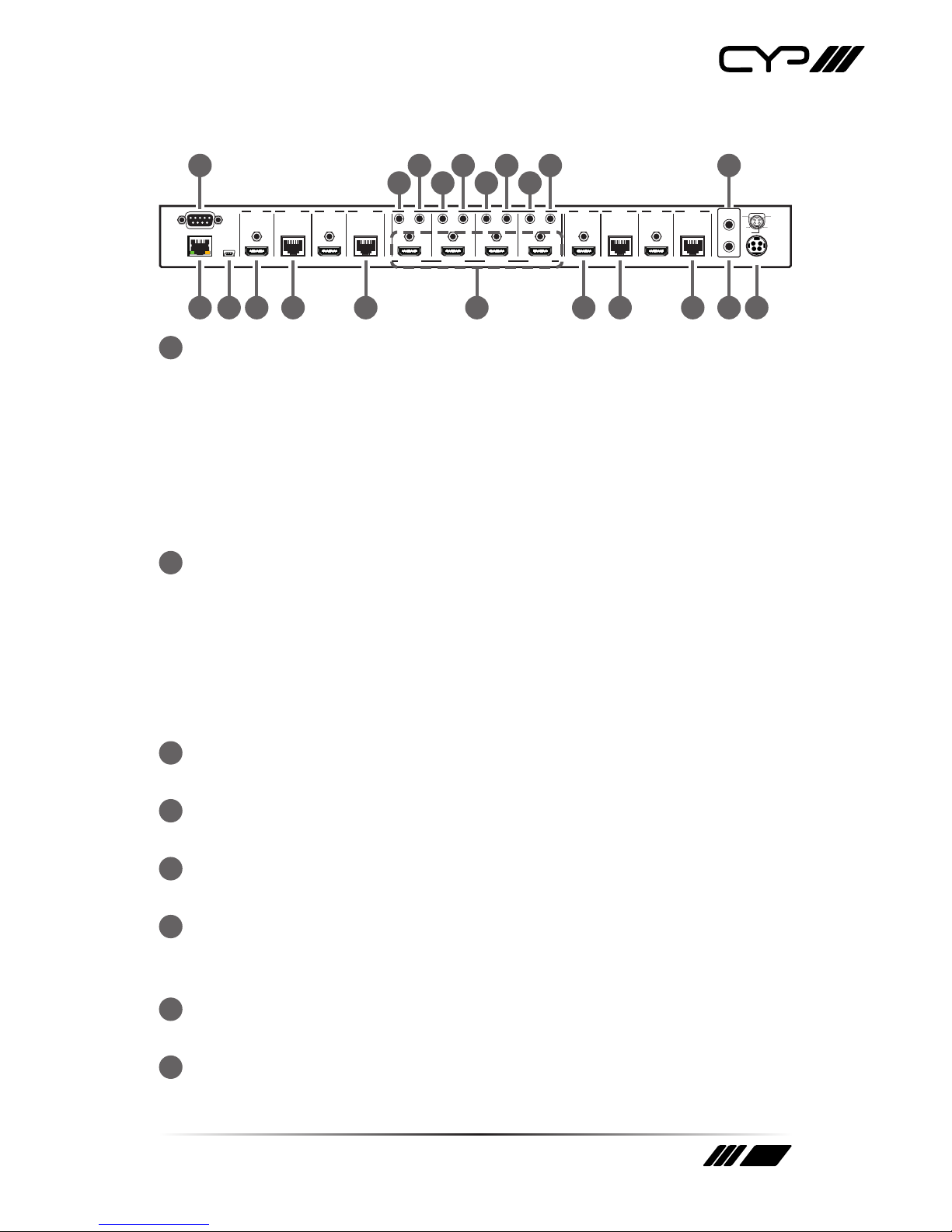
1RS-232: This slot is to connect with D-Sub 9pin cable from the PC/
Laptop device for RS-232 control.
Note: This RS-232 obtain routable function that is, from the Matrix it can
send commands to all receivers or from receiver sides it can also send
commands to control the Matrix. In order to allow the receivers to send
command to control the Matrix, a null modern cable/adaptor is required.
In order to allow the receivers to send command to control the Matrix, a
null modern cable/adaptor is required.
2IP & Ethernet: This port is for Telnet and Web GUI control. Connect
and active network system with RJ45 terminated cable (for details,
please refers to RS-232 & Telnet commands and Web GUI Control
sections). Also, it allows Ethernet access when connecting to an active
network source or when any of the CAT outputs has the Ethernet link.
Warning: Please do not connect this port directly to the PC/Laptop as the
Telnet function will not work.
3Service: This slot is to connect with mini USB B type cable for rmware
update only.
4HDMI OUT A/C/E/G: These slots are to connect with HD TV/display for
instant display.
5CAT5e/6/7 OUT B/D/F/H: These slots are to connect with HDMI over
CAT5e/6/7 Receiver for signal extension up to 100m.
6HDMI IN 1~4: These slots are to connect to input source equipment
such as DVD player or Set-Top-Box with HDMI cable or DVI to HDMI
converter cable for input signal sending.
7IR IN 1~4: These slots are to connect with IR Extender included in the
package for IR signal receiving.
8IR OUT 1~4: These slots are to connect with IR Blaster included in the
package for IR signal sending.

10
9ALL IR OUT: This slot is to connect with the IR Blaster for IR signal
received from receiver sides and send to the source side.
10 ALL IR IN: This slot is to connect with the IR extender for IR signal
receiving and send out to receiver sides.
11 DC24V: This slot is to plug the power cord with adaptor included in
the package and then connect them with AC wall outlet for power
supply.
6.3 Side Panel
1
1Ventilator: These are fan ventilator area, DO NOT block these area or
cover it with any object.
6.4 Remote Control
1Power: Press this button to
switch ON the device or set it to
standby mode.
2IN: Input ports selection 1~4.
3OUT: Output ports selection
A~H.
H
8
1A
B
2
C
3
4D
5E
6F
7G
CR-110
IN OUT
3
2
1

11
6.5 IR Pin Assignment
3
1
3
2
2
1Power 5V
IR Blaster Signal
NC
IR Signal
Power 5V
Ground
IR Extender
IR Blaster
6.6 RS-232 Protocols
PU-444HBTE Remote Control Console
PIN Assignment PIN Assignment
1 NC 1 NC
2Tx 2 Rx
3 Rx 3 Tx
4 NC 4 NC
5 GND 5 GND
6 NC 6 NC
7 NC 7 NC
8 NC 8 NC
9 NC 9 NC
Baud Rate: 19,200bps
Data bit: 8 bits
Parity: None
Flow Control: None
Stop Bit: 1

12
6.7 RS-232 & Telnet Commands
Command Description
A1~A4 Switch output A to 1~4
B1~B4 Switch output B to 1~4
C1~C4 Switch output C to 1~4
D1~D4 Switch output D to 1~4
E1~E4 Switch output E to 1~4
F1~F4 Switch output F to 1~4
G1~G4 Switch output G to 1~4
H1~H4 Switch output H to 1~4
A0~H0 Switch output A to F mute
ABCD…1~ABCD…4 Switch output ABCD… to 1~4
ABCD….0 Mute output ABCD… at the same time
SETIP<IP> <SubNet>
<GW>
Setting IP. SubNet. GateWay (Static IP)
RSTIP IP Conguration Was Reset to Factory
Defaults <DHCP>
IPCONFIG Display the current IP conguration
P0 POWER OFF
P1 POWER ON
I1~I4 Switch all the output to 1~4
I0 Mute all the output
ST Display the current matrix status and F/W version
RS System Reset to A1, B1, C2, D2, E3, F3, G4, H4
EM Setting EDID MODE. 1-STD 2-TV
?Display all the available commands

13
UARTBAUD? Display baud rate setting 1~6
1: 9600bps
2: 14400bps
3: 19200bps
4: 38400bps
5: 57600bps
6: 115200bps
UARTBAUD2 Set output B’s baud rate from 1~6
UARTBAUD4 Set output D’s baud rate from 1~6
UARTBAUD6 Set output H’s baud rate from 1~6
UARTBAUD8 Set output H’s baud rate from 1~6
UARTSW? Display output’s UART status Allowing Matrix to
send commands to Receiver’s connected device.
UARTSW0 Switch to MCU. Allowing Receivers to
send commands to Matrix.
UARTSW2 Switch to output B and allow Matrix to send com-
mands to Receiver’s connected device.
UARTSW4 Switch to output D and allow Matrix to send com-
mands to Receiver’s connected device.
UARTSW6 Switch to output F and allow Matrix to send com-
mands to Receiver’s connected device.
UARTSW8 Switch to output H and allow Matrix to send com-
mands to Receiver’s connected device.
Quit Exit (for telnet only)
Note: Commands will be not executed unless followed by a carriage
return. All commands are not case-sensitive. Commands are under
RS-232 control only.

6.8 Telnet Control
Before attempting to use the telnet control, please ensure that both the
Matrix (via the 'CONTROL' port) and the PC/Laptop are connected to the
active networks.
To access the telnet control in Windows 7, click on the 'Start' menu and
type "cmd" in the Search eld then press enter
Under Windows XP go to the 'Start' menu and click on "Run", type "cmd"
with then press enter.
Under Mac OS X, go to Go→Applications→Utilities→Terminal See below
for reference.
Once in the command line interface (CLI) type "telnet", then the IP address
of the unit and "23", then hit enter.
Note: The IP address of the Matrix can be displayed on the device's LCM
monitor by pressing the Menu button twice.

This will bring us into the device which we wish to control. Type "HELP" to
list the available commands.
Type “IPCONFIG”To show all IP congurations. To reset the IP, type “RSTIP”
and to use a set static IP, type ”SETIP” (For a full list of commands, see
Section 6.7).
Note: All the commands will be not executed unless followed by a carriage
return. Commands are case-insensitive. If the IP is changed then the IP
Address required for Telnet access will also change accordingly.

16
6.9 Web GUI Control
On a PC/Laptop that is connected to the active network as the Matrix,
open a web browser and type device's IP address on the web address
entry bar. The browser will display the device's status, control and User
setting pages.
Click on the 'Control' tab to control power, input/output ports, EDID and
reset mode.

17
Clicking on the 'User Setting' tab allows you to reset the IP conguration.
The system will ask for a reboot of the device every time any of the
settings are changed. The IP address needed to access the Web GUI
control will also need to be changed accordingly on the web address
entry bar.

18
7. CONNECTION DIAGRAM
SERVICE
RS232
IP &
ETHERNET
BDA
F HE
DC 24V
IR OUT
IR IN
ALL
1
IR IN IR OUT
2
IR IN
IR OUT
3
IR IN IR OUT
4
IR IN IR OUT
HDMI IN 1HDMI IN 2
HDMI IN 3 HDMI IN 4
HDMI OUT CAT5e/6/7 OUT CAT5e/6/7 OUT
G
HDMI OUT
C
HDMI OUT
1
2
3
4
V+
GND
GND GND
V+
IR BLASTER
1.5m
60°
IR EXTENDER
7m
3m 3m
60°
m
ZONE
DZONE EZONE FZONE GZONE H
1
2 3 4
ZONE
CZONE AZONE
B
C
D
E
F
B
A
G
H
RX Power
Extender Blaster
IR 2
IR 1
RS232 Out CAT5e/6In
Link
RX Power
Extender Blaster
IR 2
IR 1
RS232 OutCAT5e/6In
Link
RX Power
Extender Blaster
IR 2
IR 1
RS232 OutCAT5e/6In
Link
RX Power
Extender Blaster
IR 2
IR 1
RS232 Out CAT5e/6In
Link
RS-232 Equipped PC
or Control System
Network Router
with Ethernet
Blu-ray Player
HDMI
Input
HDMI
Input
HDMI
Input
HDMI
Input
HDMI
Output Power
Supply
CAT5e/6/7
Outputs
IR In/Out
IR In/Out IR In/Out IR In/Out
IR OUT
ALL
IR IN ALL
Media Server
Set-top BoxSatellite Receiver
RS-232

19
7. CONNECTION DIAGRAM
SERVICE
RS232
IP &
ETHERNET
BDA
F HE
DC 24V
IR OUT
IR IN
ALL
1
IR IN IR OUT
2
IR IN IR OUT
3
IR IN IR OUT
4
IR IN IR OUT
HDMI IN 1HDMI IN 2
HDMI IN 3 HDMI IN 4
HDMI OUT CAT5e/6/7 OUT CAT5e/6/7 OUT
G
HDMI OUT
C
HDMI OUT
1
2
3
4
V+
GND
GND GND
V+
IR BLASTER
1.5m
60°
IR EXTENDER
7m
3m 3m
60°
m
ZONE DZONE
EZONE
FZONE
GZONE H
1 2
3 4
ZONE CZONE AZONE B
C
D
E
F
B
A
G
H
RX Power
Extender Blaster
IR 2
IR 1
RS232 Out CAT5e/6In
Link
RX Power
Extender Blaster
IR 2
IR 1
RS232 OutCAT5e/6In
Link
RX Power
Extender Blaster
IR 2
IR 1
RS232 OutCAT5e/6In
Link
RX Power
Extender Blaster
IR 2
IR 1
RS232 Out CAT5e/6In
Link
RS-232 Equipped PC
or Control System
Network Router
with Ethernet
Blu-ray Player
HDMI
Input
HDMI
Input
HDMI
Input
HDMI
Input
HDMI
Output
Power
Supply
CAT5e/6/7
Outputs
IR In/Out IR In/Out
IR In/Out IR In/Out
IR OUT
ALL
IR IN ALL
Media Server
Set-top BoxSatellite Receiver
RS-232

20
8. SPECIFICATIONS
8.1 Technical Specication
Video Bandwidth 225MHz/6.75Gbps
Input Ports 4 x HDMI, 5 x IR Extender, 1 x RS-232, 1 x LAN
(Control only), 1 x RJ45 (Control Only), 1 x USB
Mini-B (Service Only)
Output Ports 4 x HDMI, 4 x CAT5e/6/7, 5 x IR Blaster
Power Supply 24V / 3.75A DC (US/EU standards, CE/FCC/UL
certied)
ESD Protection Human Body model:
± 8kV (air-gap discharge)
± 4kV (contact discharge)
Dimensions (mm) 436(W) x 249(D) x 44(H)
436(W) x 255(D) x 48(H)/Including Jacks
Weight 3344g
Chassis Material Metal
Colour Black
Operating Temperature 0˚C~40˚C / 32˚F ~ 104˚F
Storage temperature -20˚C~60˚C / -4˚F ~ 140˚F
Relative Humidity 20~90% RH (no condensation)
Power Consumption 40W
8.2 CAT5e/6/7 Cable Specication
Cable
Type
Range Pixel clock
rate
Video Data
Rate
Supported Video
CAT5e/6/7 100 m <=225 MHz <=5.3 Gbps
(HD Video)
Up to 1080p, 60 Hz,
36 bits, 3D (data rates
lower than 5.3 Gbps or
below 225 MHz TMDS
clock).
Table of contents
Other CYP Switch manuals