2
ENGLISH
Front Panel Connectors
Figure 3: Front panel connectors
# Interface Description
1Ports 1 - 4
10/100 Mbps PoE-capable ports,
used for connecting Ethernet
devices and PoE-powered devices.
2
10/100 Mbps Ethernet ports
for uplink connections to
NVR, storage or core switch.
Table 2: Front connector description
Rear Panel Connectors
Figure 4: Rear panel connectors
# Connector Description
1DC Power Input Input jack for the power adapter.
2SWITCH GND Screw used to secure a grounding
wire to connect the switch to ground.
Table 3: Rear connector description
DIP Switch
Before You Begin
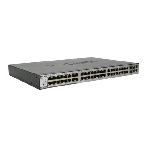
This Quick Installation Guide gives you step-by-step
instructions for setting up your DSS-100E-6P 6-port
PoE Surveillance Switch. The model you have purchased
may appear slightly dierent from the one shown
in the illustrations.
Package Contents
This DSS-100E-6P package should include the
following items:
• 1 x DSS-100E-6P
• 1 x Power adaptor
• 1 x Quick Installation Guide
If any of the above items are damaged or missing,
please contact your local D-Link reseller.
Hardware Overview
LED Indicators
Figure 1, 2: LEDs
# LED Status Description
1Power
Solid
green
The switch is powered on.
O The switch is turned o.
2
Link/
ACT
(Left
Led)
Solid
green
There is an active link negotiated
on this port.
Blinking
green
There is trac on the port.
O There is no active link on this port.
3
PoE
(Right
Led)
Solid
green
The port is providing power to the
connected PoE-powered device.
Blinking
green
Indicates a PoE-powered device
is connected to this PoE port,
but the switch has insufficient
remaining power budget to
power the device.
O There is no PoE-powered device
connected to this port.
Table 1: LED overview
DSS-100E-6P
1
2
3
12
Ports 5 - 6
1 2
The DIP switch on the rear panel allows you to
configure the operating mode of the DSS-100E-6P.
DIP
Switch Function Controlled
Standard
Switch all ports can communicate with each
other port and work as a common Unmanaged
Switch. *1 to 4 port supports Power over Ethernet
and transmit data at 10/100 Mbps.** 1 to 2 port
supports port priority to optimize port cache.
Extend &
Isolate 1 to 4 port can’t communicate with
each other, but each of them can
communicate with port 5 and 6.
The data rate of 1 to 4 port is limited to 10 Mbps,
whereas the maximum transmission distance
of the port is increased to 250 meters.
Table 4
