ENGLISH
13
4FUNCTION
The electronics automatically control starting and stopping (ON/OFF) of the pump depending on the request for water.
The electronics protect the pump from faults in the Non Return Valve (NRV) in the pump casing, which are generally caused by dirt or sand
deposits. The deposits may prevent the NRV from closing, even in the absence of water. Adequate maintenance of the NRV is therefore
recommended.
The pump is automatically switched off every hour; if everything is normal, the user only notices a very slight drop in pressure lasting a few
seconds. If the NRV is blocked, the pump will go into alarm and can be restarted after removing the causes of the obstruction, preferably by
disconnecting and reconnecting it to the power supply. However, the alarm stops if the valve is released mechanically.
The electronics protect the pump from dry running, that is without water (see anti-DRYRUN function).
The electronics protect the pump from false starts in the event of water bubbling (see anti-burping function).
4.1 Pump start and stop conditions
When water is consumed in the water supply network, the pump starts when the starting conditions are met. This is done, for example, by
turning on a tap and lowering the pressure in the system. The pump stops again when the water consumption stops, that is when the tap is
turned off.
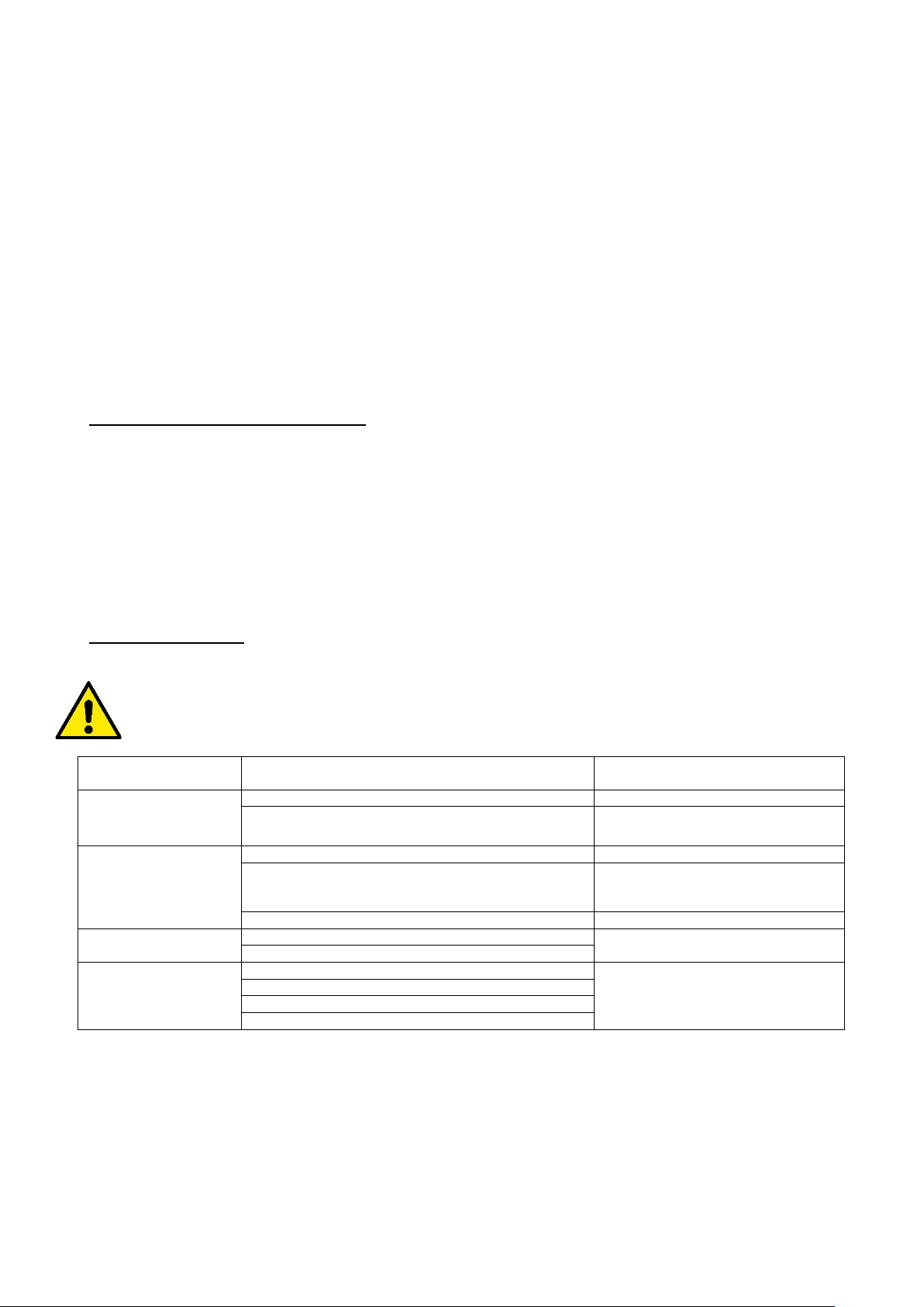
Start conditions
The pump starts when one of the following conditions is met:
- The flow rate is higher than the minimum flow rate of 2 l/min (0.53 rpm).
- The pressure is lower than the starting pressure (CUT-IN). The cut-in is factory set at 2.4 bar (34.8 psi).
If the pump is equipped with a control panel, the cut-in is variable.
Stop conditions
The pump stops with a delay of 10 seconds when:
-The flow rate is lower than the minimum flow rate with pressure above the CUT-IN.
-The pump stops even when there is no water, safeguarding the motor (see ANTI DRYRUN function).
- Various alarms.
4.2 Pump On – OFF
The pump motor is powered by the electronic control board, located inside the pump body, with an alternating voltage equal to that of the
electrical power mains.
The pump power supply is supplied to the motor according to the evolution of the user's requirements and the hydraulic conditions of the
system, as described below.
CUT-IN / Flow – Normal operation
Normally (in the absence of alarms and when the pump has been primed) the motor is switched on immediately if the pressure is lower than the
cut-in (see paragraph 4.1) or if there is flow. The motor is switched off if the pressure is greater than the CUT-IN and the flow is absent
(however, after 10 seconds of permanence in this condition).
Connection to the power mains - first priming of the pump
After connecting the pump to the mains, the pump motor is switched off and the non-return valve is at rest: if this is not the case, the pump stops
and the motor will never start (see ANTIFLOOD paragraph).
In the normal case, however, the pump behaves as follows:
• If the hydraulic circuit upstream from the pump has a pressure higher than CUT-IN, the pump motor does not start, the priming is finished
regularly.
• If the circuit is not under pressure (P<CUT-IN), the pump motor is started. In this case:
oIf the hydraulic circuit goes under pressure (P>CUT-IN) and there is no flow, for example because the delivery tap is closed,
the motor is switched off 10 seconds after starting: the pump is primed.
oIf there is no flow or pressure for 20 seconds (P<CUT-IN), the pump goes into DRYRUN alarm and is switched off: the pump
is not primed.
oFinally, if there is flow, the pump is primed and runs normally.
Anti DRYRUN
If no pressure and flow is detected during normal operation (or during pump start-up) for 20 seconds, the pump will go into DRYRUN alarm and
the motor will be switched off.
The pump control electronics will try to restart the pump until the dry running condition, i.e. the absence of flow and pressure, is no longer
detected.
These restart attempts will be scheduled as follows: