Daewoo DX-C811N User manual

Operating Instructions
channel DVR
(Digital VIdeo Recorder)
8
Model : DX-C811N

DIGITAL VIDEO RECORDER
2
SAFETY PRECAUTIONS
CAUTION
RISK OF ELECTRIC SHOCK
DO NOT OPEN
CAUTION:
TO REDUCE THE RISK OF ELECTRIC SHOCK, DO NOT REMOVE COVER (OR BACK).
NO USER SERVICEABLE PARTS INSIDE. REFER SERVICING TO QUALIFIED
SERVICE PERSONNEL.
The lightning flash with arrowhead symbol, within an equilateral
triangle, is intended to alert the user to the presence of un
insulated “dangerous voltage”within the product’s enclosure that
may be of sufficient magnitude to constitute a risk of electric
shock to persons.
The exclamation point within an equilateral triangle is intended to
alert the user to the presence of important operating and
maintenance (servicing) instructions in the literature accompanying
the appliance.
WARNING:
TO PREVENT FIRE OR ELECTRIC SHOCK HAZARD, DO NOT EXPOSE THIS
APPLIANCE TO RAIN OR MOISTURE.

DIGITAL VIDEO RECORDER
3
PRECAUTIONS
• Refer all work related to the installation of this product to qualified service personnel or system
installers.
• Do not block the ventilation opening or slots on the cover.
To prevent the appliance from overheating, place it at least 5 cm (2 inches) away from the wall.
• Do not drop metallic parts through slots.
This could permanently damage the appliance. Turn the power off immediately and contact qualified
service personnel for service.
• Do not attempt to disassemble the appliance.
To prevent electric shock, do not remove screws or covers. There are no user-serviceable parts inside.
Contact qualified service personnel for maintenance.
• Handle the appliance with care.
Do not strike or shake, as this may damage the appliance.
• Fully charge up the backup battery.
Keep the appliance turned on for at least 48 hours to recharge the backup battery. This procedure is
necessary when using the appliance for the firs time or after it has been unplugged for a long time from the
AC outlet. Insufficient charging of the battery may cause erasure of settings if the AC power supply should
fail. The battery, if fully charged, will back up the settings for 480 hours in an ordinary environment.
• Do not expose the appliance to water or moisture, nor try to operate it in wet areas.
Do take immediate action if the appliance becomes wet. Turn the power off and refer servicing to qualified
service personnel. Moisture may damage the appliance and also cause electric shock.
• Do not use strong or abrasive detergents when cleaning the appliance body.
Use a dry cloth to clean the appliance when it is dirty. When the dirt is hard to remove, use a mild
detergent and wipe gently.
• Do not operate the appliance beyond its specifiedtemperature, humidity or power source ratings.
Do not use the appliance in an extreme environmentwhere high temperature or high humidity exists.
Use the appliance at temperatures within +5°C-+40°C (41°F -104°F) and a humidity below 90 %.
The input power source for this appliance is 110V-220V AC 50/60Hz.

DIGITAL VIDEO RECORDER
4
Contents
ⅠControls
1. Front Panel ------------6
2. Rear Panel ------------8
3. Remote Controller ------------9
ⅡInstallation & Connections ----------- 10
1. Camera, Monitor, Microphone, Alarm sensor and Power cord
2. Alarm inputs and Alarm outs
3. PAN/TILT/ZOOM Camera connections
4. PC system requirement for NETWORK Connection
ⅢOperation
1. Time & Date setting. ------------- 12
2. Screen Position Adjustment. ------------- 12
3. Live View ------------- 13
1) Live view mode switching
2) Border Line color
3) Brightness, Contrast & Color adjustment
4. Basic Recording ------------- 16
5. Alarm Recording ------------- 19
6. Pre Recording ------------- 21
7. Schedule Recording ------------- 22
8. Motion Detection Recording ------------- 24
9. Time & Date Search ------------- 26
10.Playback ------------- 27
1) Basic playback
2) Reverse playback
3) Field by field playback
4) Adjusting playback speed
5) Audio Play back
11. Alarm / Motion List Search ------------- 30
12. System Set ------------- 31

DIGITAL VIDEO RECORDER
5
13. Network Set ------------- 35
14. Information & Log List ------------- 36
15. Zoom ------------ 37
16. PAN/TILT/ZOON Camera Control ------------- 37
17. External Backup Device Control (DAT24)------------- 38
ⅣClient Program
1. How to install and connect?------------- 41
2. Features ------------- 43
3. Image file down load from the DVR server ------------- 45
4. DVR Setting ------------- 46
5. Local Player ------------- 50
ⅤHow to connect modem ------------- 52
ⅥSpecification & Contents
1. Specification ------------- 60
2. Contents

DIGITAL VIDEO RECORDER
6
Ⅰ
Controls
1. Front Panel Controls
1) POWER button
Press this button to turn the power on; press again to turn the power off. The POWER
LED (red) lights/goes off when the power is on/off. It flashes when switching during
initializing and disk checking.
2) LOCK button
Press this button to lock all unit’s key buttons including the remote controller.
The LOCK LED (green) lights/goes off when the lock is on/off. To release press it
again and enter the password.
3) RESTORE button
Press this button to restore recorded data to the main hard disk from an archive
device only when an external USB DAT24 is connected.
4) SCHEDULE button
Press this button to make scheduled recording standby. The SCHEDULE LED (green)
lights/goes off when the schedule is on/off.
5) INFO button
Press the button to display current system information; press again to display log list.
6) BACKUP button
Press this button to begin making a backup copy of the hard drive. If there is no
peripheral recording device connected, this button cannot be used.
7) PAN/TILT/ZOOM button
Press this button to control a PAN/TILT/ZOOM camera via RS-232 connection.
8) ZOOM button
Press this button to display zoom area box; press again to enlarge the image.
1 2
6 7 8 10 13 19 201615
3 4 5 9 12 14 1711 18

DIGITAL VIDEO RECORDER
7
Pressing cursors can move this zoom area.
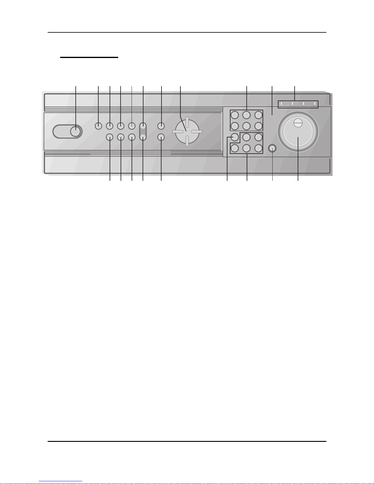
9) MENU button
Press this button to display the MAIN MENU screen.
It is also used as EXIT button to exit all kinds of OSD screen.
10) CLEAR button.
In Zoom mode, pressing this button reduces the image.
In stop mode and playback mode, pressing this button disappears time & date OSD.
Pressing it again appears the OSD.
On ‘RECORD GROUP SET’menu, it sets each channel ‘Motion Detection’.
11) Direction (€•ƒ„) buttons.
In Menu setup mode, used to move the cursor.
In Zoom mode, used to move the zoom area.
12) TIME SEARCH button
Press this button to display the Time Search menu.
13) ALARM SEARCH button
Press this button to display the Alarm Search menu.
14) Numeric buttons (NO. 1~9)
Used to enter the password and select the camera numbers.
15) Quad/Sequence, 0 button
Press this button to display the cameras in quad mode or to switch sequence function.
In addition, this button can be used as number 0 to set the password.
16) AUDIO PB button
Press this button to synchronize the sound track with the scenes.
17) Remote control signal receiver.
18) Mode Indicator.
19) SHUTTLE HOLD button
This button retains the selected playback or reverse playback speed.
Rotate the SHUTTLE ring to the desired search speed, and then press the SHUTTLE
HOLD button while holding the SHUTTLE ring at the selected search speed. Search
speed will be maintained even when the SHUTTLE ring is returned to its original
position.
20) Jog and shuttle operation
SHUTTLE ring
Use the ring to set various menus and search functions, to adjust the playback speed,
and to rewind or forward the image.
JOG dial
Use the dial to set various menus and search functions, and to forward or reverse the
image during playback (field-by-field).

DIGITAL VIDEO RECORDER
8
2. Rear Panel Connectors
INOUT
USB
CAMERA
IN
AUDIO MIC
5
1
6 7
2 3
S-VIDEO8
4COMPOSITE
ETHERNET RS-232C
1 2
63 4 5 7 8 9 10
11
12
VIDEO OUT
ALARM IN1
ALARM IN2
ALARM IN3
ALARM IN4
GND
ALARM IN5
ALARM IN6
ALARM IN7
ALARM IN8
GND
ALARM OUTPUT
GND
100V 230V
AC IN
1) CAMERAIN connectors
These are BNC input connectors for 8 cameras
2) VIDEOOUT connectors
A BNC standard composite video output connector
3) AUDIO OUT connector
This is an RCA output for an audio signal.
4) AUDIO IN connector
This is an RCA input for an audio signal.
5) MIC jack
This is an input connector for a microphone.
6) S-VHS OUT connector
An S-VHS connector for separate luminance and chrominance (Y/C) signals This is
an RCA input connector for an audio signal.
7) USB 2.0 connector
This connector is for peripheral recording device.
8) ALARM IN/OUT terminal.
9) RJ-45 ETHERNET connector
10)RS-232C
11)AC power socket
12)Power Fan

DIGITAL VIDEO RECORDER
9
3. Remote Controller
DVR ID
ZOOM
-._
P/T/Z
ABC DEF
MNOJKLGHI
VWXSTU
YZ@
MENU
DISPLAY
PQR
AUDIO-PB
STANDBY/ON
F1 F2 F3 F4
F5 F6 F7 F8
ENTER
A-
S
E
A
RC
H
C
A
N
C
E
L
T
-
S
EA
RCH
L-SEARCH
STEP
REW
REC
INFO LOG ALARM
STOP TIMER
PLAY FF
BACKUP RESTORE
Option (Not used)
Zoom AUDIO-PB
DISPLAY/QUAD
CANCEL
ALARM SEARCH
FF
TIMER
ALARM NOISE OFF
BACKUP
STOP
PLAYBACK
RESTORE
POWER
Number/Letter
MENU
CURSOR
ENTER
TIME SEARCH
LIST SEARCH
REW
REC
SYSTEM INFORMATION
LOG
Field by Field
Pan/Tilt/Zoom
Option (Not used)

DIGITAL VIDEO RECORDER
10
ⅡInstallation & Connections.
1. Camera, Monitor, Microphone, Alarm sensor and Power cord.
VIDEOOUT
or
S-VIDEO OUT
AUDIOOUT
Up to 8 cameras
MICIN
MONITOR
CAMERA#1
MICROPHONE
POWER CORD
SENSOR#1
ALARM IN
GND
INOUT
USB
CAMERA
IN
AUDIO MIC
5
1
6 7
2 3
S-VIDEO8
4COMPOSITE
ETHERNET RS-232C
VIDEO OUT
AL ARM IN1
AL ARM IN2
AL ARM IN3
AL ARM IN4
GN D
AL ARM IN5
AL ARM IN6
AL ARM IN7
AL ARM IN8
GN D
AL ARM OUT PU T
GN D
2. Alarm inputs and Alarm outs.
ALARMIN1
ALARMIN2
ALARMIN3
ALARMIN4
GND
GND
ALARMIN6
ALARMIN7
ALARMIN8
ALARMOUTPUT
ALARMIN5
GND
±Connection of N.O (Normally Open)

DIGITAL VIDEO RECORDER
11
3. PAN/TILT/ZOOM Camera
1) C&B Technology (Model: PTZ102)
2) The other models: as buyers request; the camera sample and protocol should be
supported.
RS485 to RS232C Converter
PTZ CAMERA
CAM1 CAM2 CAM3 CAM4
CONTROL LINE
IN
OUT
USB
CAMERA
IN
AUDIO MIC
5
1
6 7
2 3
S-VIDEO8
4COMPOSITE
ETHERNET RS-232C
VIDEO OUT
A LARM IN 1
A LARM IN 2
A LARM IN 3
A LARM IN 4
G ND
A LARM IN 5
A LARM IN 6
A LARM IN 7
A LARM IN 8
G ND
A LARM OU TPUT
G ND
CAM5 CAM6 CAM7 CAM8
4. PC system requirementfor Network connection.
(a) 500MHz CPU
(b) 128MB RAM
(c) 4MB Video Card
(d) Windows 98SE, 2000, ME
(e) Spare 10/100-BaseT Ethernet Port
(f) RJ-45 Network Cable
NOTE:
We do not guarantee for all kind of PC even though the PC meets the
specification.

DIGITAL VIDEO RECORDER
12
ⅢOperation
1. Time / Date Setting
1) When the DVR is turned on, ‘TIME/DATE SET’menu appears after initializing.
2) Then enter Time & Date with numeric buttons (0-9).
3) After that, press the “Menu”button to set-up and exit.
<**> Note: There is a rechargeable battery inside the DVR to keep the DVR’s setting information.
The battery needs to be recharge at least 6 hours when the DVR is installed. The battery
would keep the setting information for 10 days if there is a power failure.
<**> Note: Factory default password is “000000”. It is recommended to change the “Password”
when you install the DVR. See the 30 page
2. Screen Position Adjustment.
While live view or playback, press the direction (€•ƒ„) buttons.
€: The screen moves downward.
•: The screen moves upward.
ƒ: The screen moves left.
„: The screen moves right.

DIGITAL VIDEO RECORDER
13
3. Live View
1) Live view mode switching
Press the ‘QUAD’(田口) Button to switch display modes
: 9 à6à8àQuad
To switch one of small view to main view on 6 or 8 channel display mode
-Press the“NO 9”button.
-While the boarder line of CH1(main) flashes press the desired channel
number.
2) Border Line Color
è
a. Press the “MENU”button to go in the “MAIN MENU”
b. While the “DISPLAY SET”flashes press the„button or turn the SHUTTLE
ring to the right to enter
c. Press the €button to move the cursor to the “BORDER LINE”.
d. Then, press the„button to select a line color.
BLACK (default) ©ª DARK GRAY ©ª GRAY ©ª WHITE

DIGITAL VIDEO RECORDER
14
3) Brightness, Contrast & Color adjustment
è
a. Press the “MENU”button to go in the “MAIN MENU”
b. While the “DISPLAY SET”flashes press the„button or turn the SHUTTLE
ring to the right to enter
c. Press the €button to move the cursor to the “CAMERA SELECT”.
d. Then, press the„buttonto select adesired camera.
CAM1 (default) ©ª CAM2 ©ª CAM3 ©ª CAM4©ª CAM5
©ª CAM6©ª CAM7©ª CAM8
e. After camera selection, press the €button to move the cursor down to the
“BRIGHT NESS”, “CONTRAST”or “COLOR”
f. Then, press the„button to adjust.
ITEMDEFAULT ADJUTMENT
BRIGHTNESS
50%
-Camera number can be switched by pressing the number
buttons (1,2,3,~8 )
-The brightness of each camera can be adjusted by
pressing tubuttons or by turning the SHUTTLE ring
CONTRAST
50%
-Camera number can be switched by pressing the number
buttons (1,2,3~8)
-The contrast of each camera can be adjusted by pressing
tubuttons or by turning the SHUTTLE ring

DIGITAL VIDEO RECORDER
15
COLOR
50%
-Camera number can be switched by pressing the number
buttons (1,2,3~8)
-The contrast of each camera can be adjusted by pressing
tubuttons or by turning the SHUTTLE ring
SEQ. BYPASS
(Camera By
pass)
NO YES, or NO
If the SEQ. BYPASS is YES, the selected camera will not be
shown in the sequential display mode.
To complete the setting and exit, press MENU button or SHUTTLE HOLD
button.

DIGITAL VIDEO RECORDER
16
4. Basic Recording.
è
1) Press the “MENU”button to go intothe “MAIN MENU”
2) Press the €button to move the cursor to the “RECORD GROUP SET”
3) While the “RECORD GROUP SET”flashes press the„button or turn the
SHUTTLE ring to the right to enter
4) Then, set the picture quality and recording rate of each camera.
ITEM DEFAULT ADJUTMENT
DIFINE GROUP
GROUP1
Up to 4 different recording modes (GROUP) can be pre-
determined.
GROUP1
⇔
GROUP2
⇔
GROUP3
⇔
GROUP4
PICTURE
QUALITY
HIGH+
Select the picture quality
SUPER+ ©ª SUPER ©ªHIGH+ ©ª HIGH ©ª
MID+ ©ª MID ©ª LOW+ ©ª LOW
3F/S
Select the capture rate of each camera.
NTSC setting
30F/S©ª15F/S©ª10F/S©ª7F/S©ª6F/S ©ª5F/S©ª4F/S
©ª3F/S©ª2F/S©ª1F/S ©ª30F/M (minute) ©ª20F/M©
ª12F/M©ª6F/M©ª4F/M©ª3F/M©ª2F/M©ª1F/M©ª00F/S
4F/S PAL setting
25F/S©ª12F/S©ª10F/S©ª7F/S ©ª6F/S©ª5F/S©ª4F/S
©ª2F/S©ª3F/S©ª1F/S©ª30F/M(minute)©ª20F/M©ª12F/
M©ª6F/M©ª4F/M ©ª3F/M©ª2F/M©ª01F/M©ª00F/S
CAMERA1 ~
CAMERA 8
Real-Time Recording
If you wish to record in real-time mode, set only camera 1 & camera 2.
NTSC: 30F/S, PAL: 25F/S
<Note> when real-
time recording (camera 1 & 2 or one of two cameras),
the others will not activate at all, even the network image transmission of
the camera 3 ~8.

DIGITAL VIDEO RECORDER
17
5) Press the“MENU”button to set up and go back to the “MAIN MENU”
è
6) Then, go into the“RECORD SET”
7) On the “RECORD GROUP”, select one of four Recording modes (Group) you
wish to record.
8) Select an audio recording source (MIC or LINE) if audio is connected.
9) After that, press the “MENU”button to exit.
10)Press the REC button. Then, the red REC LED lights on the front panel and
recording starts.
11)To stop recording, pres the “STOP”button.
cRecording Speed (F/S)
CH1
1
-
30
1
-
15
1
-
10
1
-
7
…
0
CH2
1
-
30
1
-
15
1
-
10
1
-
7
…
0
CH3
X
1
-
15
1
-
10
1
-
7
…
0
CH4
X
1
-
15
1
-
10
1
-
7
…
0
CH5
X
X
1
-
10
1
-
7
…
0
CH6
X
X
1
-
10
1
-
7
…
0
CH7
X
X
X
1
-
7
…
0
CH8
X
X
X
1
-
7
…
0
<Note> Recording Speed setting.
①NTSC 30F/S(PAL: 25F/S) : Only for Channel 1 and 2.
If you select the real-time recording speed (NTSC: 30F
/S,
PAL: 25F/S), it automatically makes disable to record for the
rest channels 3~8.
②NTSC 15F/S(PAL: 12F/S) : It applies to Ch 1~Ch4.
③NTSC 10F/S(PAL: 10F/S) : It record 6 channels-Ch 1~Ch6.

DIGITAL VIDEO RECORDER
18
<Note>Estimated Recording Time varies due to picture quality and capture rate and is updated every
20 seconds due to variation of picture size.
When REPEAT RECORD is NO;
Estimated Recoding Time shows the time when HDD is reached to the end.
When REPEAT RECORD is YES; Estimated Recording Time shows overwriting time of whole HDD.
Estimated Recording Time
Indicate there was Power Loss
Recording Mode
Indicate there is Video Loss
Month, Date, Year, Day, Time Available HDD space
Current Recording Channels
: Turn to Yellow color

DIGITAL VIDEO RECORDER
19
5. Alarm Recording
è
1) Press the“MENU”button to go into the “MAIN MENU”
2) Press the€button to move the cursor to the “ALARM RECORD SET”
3) While the “ALARM RECORD SET”flashes press the„button or turn the
SHUTTLE ring to the right to enter.
4) Settings
ITEM DEFAULT ADJUTMENT
ALARM
DURATION
60SEC
Determines the alarm recording duration after an input of
alarm signal.
20SEC ©ª 40SEC ©ª 60SEC©ª 80SEC ©ª 100SEC
©ª120SEC ©ª 180SEC ©ª 240SEC
RECORD
CAMERA
ALL
-ALL: It records all channels when Alarm occurs.
-1:1 : It records 1 channel by 1 alarm input. (SUPER+, 7 F/S)
AUDIO
RECORD
NO
Determines whether audio is recorded with images when an
alarm signal is input. It disregards the setting of audio recording
on the “RECORD SET
NO©ª MIC ©ª LINE
ALARM
BUZZER
NO YES: The buzzer Sounds if an alarm is triggered.
Stops when the alarm recording stops.
NO: inactivates the ALARM BUZZER function.
ALARM OUT LOW LOW ( 0V) ©ª HIGH (5V)
<Note>
When an alarm signal is input, the recording mode
is changed to the SUPER+ picture quality and 7 F/S for the
all cameras. When the
alarm is cleared, the recording
mode resumes to the previous recording mode.

DIGITAL VIDEO RECORDER
20
ALARM INPUT
SENSOR1
Select a sensor you wish to determine input and output type of
the alarm.
SENSOR1 ©ª SENSOR2 ©ª SENSOR3 ©ª SENSOR4
SENSOR5 ©ª SENSOR6 ©ª SENSOR7 ©ª SENSOR8
INPUT TYPE
OFF
OFF : Alarm recording OFF.
N.C (Normally Closed): Accepts alarm signals in the open state.
N.O (Normally Open): Accepts alarm signals in the closed state.
To complete the setting and exit, press MENU button or SHUTTLE HOLD button.
5) Alarm recording starts when an ALARM IN terminal is triggered by an alarm
sensor.
6) If the unit receives a new alarm signal while in the alarm recording mode, the
alarm duration is recounted from the beginning.
7) When the alarm is cleared, the recording mode resumes to the previous
recording mode.
Alarm
recording mode
Shows there is an
alarm recording
<Note> REC LED on the front panel flashes on the standby mode of Alarm recording.
Other manuals for DX-C811N
1
Table of contents
Other Daewoo DVR manuals

Daewoo
Daewoo VQ230K User manual

Daewoo
Daewoo DS-360 User manual

Daewoo
Daewoo Q253 User manual

Daewoo
Daewoo SV-871 User manual

Daewoo
Daewoo MC2128 User manual

Daewoo
Daewoo EQ250K User manual

Daewoo
Daewoo DV-K88 series User manual

Daewoo
Daewoo SV-250E User manual

Daewoo
Daewoo DX-C811N User manual

Daewoo
Daewoo DV-K224D User manual

Daewoo
Daewoo Video recorder User manual

Daewoo
Daewoo Video recorder User manual

Daewoo
Daewoo DV-K824DY User manual

Daewoo
Daewoo DVR-1989D User manual

Daewoo
Daewoo PROline VR516 User manual

Daewoo
Daewoo SQ200K User manual

Daewoo
Daewoo ST441S User manual

Daewoo
Daewoo DX-N111N User manual

Daewoo
Daewoo DSD-9502T User manual

Daewoo
Daewoo CT Series User manual