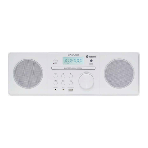
Daewoo AMI-V225M User manual

for professional technicians
INTRODUCTION OF NEW ACCESS ARRANGEMENTS
BACK
RTV servis HORVAT supplies service information documents, in PDF format, for a wide
range of electronic equipment, both consumer and professional.
Existing customers will know that, previously, service documents had to be specifically
requested by exchange of emails, to be subsequently downloaded from an address we
would notify to you. This was a cumbersome procedure, and we have now introduced a
new system to allow you to directly access our database, and to immediately download the
documents you require. Individual documents may be selected for download as required,
and we also offer CD image packs containing a selection of documents covering related or
popular equipment models.
You may register for periods covering six months or one year, which will entitle you to
download specific numbers of documents, as follows:
1. Membership 30 days, 10 documents maximum - 15 EURO
2. Membership 6 months, 600 documents maximum - 65 EURO
3. Membership 12 months, 1200 documents maximum - 125 EURO
Our new document access service is based on INTERBASE server software, which we
provide for your use, and which must be downloaded and installed on your own system.
BUT – IF YOU ARE ALREADY AN INTERBASE USER, WITH AN EXISTING INTERBASE
INSTALLATION, YOU SHOULD NOT ATTEMPT TO LOAD OUR SOFTWARE WITHOUT
FIRST CONTACTING US FOR ADVICE.
You must also note that this first release of our new system must be installed on a machine
with a direct connection to the internet for downloading. The new software will function over
your local network, you have to install our remotebrowser.exe on your local machines. For
this software, contact us.
For the installation:
1. You must download the two application programs you will need:
Interbase Server.exe
www.rtv-horvat-dj.hr
Pa
g
e 2 of 3We are a team of TV technicians who re
p
air TV's, video's, HIFI, camcorders, satelite r...
13.8.2004file://D:\more.htm

rtvhdemosetup.exe
2. First install Interbase, restart the computer, then install rtvhdemosetup.exe.
3. You will now have a working but unregistered version of our system and will be able to
download and open the demo PDF documents which have permissions already
embedded in the Demo software you have downloaded and installed, but no others. To
see these demo documents:
3.1 Launch (run) the RTV-HORVAT program.
3.2 Click on the Search tab.
3.3 Click in the box titled ‘Show Documents With Permission Only’.
3.4 Select a document by clicking on the adjacent ‘+’ button, connect to the internet and
then clicking the ‘Download’ button above the list.
3.5 The document will be downloaded, and when received can be viewed via the ‘View
Document’ button.
3.6 Note that you can only view the downloaded RTV PDF files via the RTV software,
using the Search and View procedure described above. If you attempt to open an
RTV PDF file directly from the RTV download folder, then the Acrobat reader will
open, but display of the file will be denied.
3.7 For more detailed information about facilities and use of the RTV-HORVAT system,
please consult the information available via the ‘INFORMATION’ tab in the program
display.
4. Please download a few of the sample documents to which we have provided
immediate access.
5. If everything works OK, and you wish to register for our service, then please follow the
instructions in para 10 (Registration Process) given under the program ‘INFORMATION’
tab.
We do not think you will find any major problems with this software, and will be grateful for
your forbearance for anything that does arise.
Regards
Marijan
BAC
K
Pa
g
e 3 of 3We are a team of TV technicians who re
p
air TV's, video's, HIFI, camcorders, satelite r...
13.8.2004file://D:\more.htm

Service Manual
S/N No. :
Sep.2002
DAEWOO ELECTRONICS CO., LTD.
http ://svc.dwe.co.kr
Mini Component S stem
Model:
AMI-V225M
AMI-V325M
www.rtv-horvat-dj.hr

- 1 -
TABLE OF CONTENTS
SAFETY PRECAUTIONS.................................................................................................................... 2
ADJUSTMENTS ................................................................................................................................. 4
EXPLODED VIEW AND PARTS LIST ................................................................................................ 5
WIRING DIAGRAM .............................................................................................................................7
BLOCK DIAGRAM ..............................................................................................................................8
SCHEMATIC DIAGRAM ..................................................................................................................... 9
POWER / AMP .................................................................................................................................................................. 9
CD ......................................................................................................................................................................................10
TUNER .............................................................................................................................................................................. 11
TAPE ................................................................................................................................................................................ 12
CONTROL ......................................................................................................................................................................... 13
PCB PATTERN LAYOUT.................................................................................................................... 14
ELECTRICAL PARTS LIST.................................................................................................................. 16
www.rtv-horvat-dj.hr

- 2 -
WARNING
: TO PREVENT FIRE OR ELECTRIC SHOCK, DO NOT EXPOSE
THIS APPLIANCE TO RAIN OR MOISTURE.
CAUTION :
TO REDUCE THE RISK IF ELECTRIC SHOCK, DO NOT
REMOVE COVER (OR BACK). NO USER SERVICEABLE PARTS
INSIDE.
REFER SERVICING TO QUALIFIED SERVICE PERSONNEL.
THIS SYMBOL IS INTENDED TO ALERT THE USER TO THE
PRESENCE OF UNINSULTED "DANGEROUS VOLTAGE"
WITHIN THE PRODUCT'S ENCLOSURE THAT MAY BE
SUFFICIENT MAGNITUDE TO CONSTITUTE A RISK OF
ELECTRIC SHOCK TO PERSONS.
THIS SYMBOL IS INTENDED TO ALERT THE USER TO THE
PRESENCE OF IMPORTANT OPERATING AND MAINTENANCE
(SERVICING) INSTRUCTIONS IN THE LITERATURE
ACCOMPANYINGTHEAPPLIANCE.
CAUTION
TO PREVENT ELECTRIC SHOCK, DO NOT USE THIS POLARIZED AC
PLUG WITH AN EXTENSION CORD, RECEPTACLE OR OTHER OUTLET
UNLESS THE BLADES CAN BE FULLY INSERTED TO PREVENT BLADE
EXPOSURE.
LASER SAFETY
THISUNIT EMPLOYSA LASER.ONLY QUALIFIEDSERVICE PERSONNEL
SHOULD REMOVE THE COVER OR ATTEMPT TO SERVICE THIS DEVICE
DUE TO POSSIBLE EYE INJURY.
CAUTION :
USEOFANYCONTROLS,ADJUSTMENTS, ORPROCEDURES
OTHER THAN THOSE SPECIFIED HEREIN MAY RESULT IN HAZARDOUS
RADIATION EXPOSURE.
CAUTION :
TO PREVENT ELECTRIC SHOCK, MATCH WIDE BLADE OF
PLUG TO WIDE SLOT, FULLY INSERT.
ATTENTION :
POUR EVITER LES CHOCS ELECTRIQUES, INTRODUIRE
LA LAME LA PLUS LARGE DE LA FICHE DANS LA BORNE CORRESPON-
DANTE DE LA PRISE ET POUSSER JUSQU'AU FOND.
Important Safety Instructions
- All the safety and operating instructions should be read before
the appliance is operated.
- The safety and operating instructions should be retained for
futurereference.
- All warnings on the appliance and in the operating instructions
shouldbe adhered to.
- All operating and use instructions should be followed.
1. Water and Moisture - The appliance should not be used near
water - for example, near a bathtub, washbowl, kitchen sink,
laundry tub, in a wet basement, or near a swimming pool,
and the like. 2. Carts and Stands - The appliance
should be used only with a cart or
stand that is recommended by th
manufacturer.
3. An appliance and cart combination
shouldbe moved withcare. Quick
stops, excessive force, and uneven
surfaces may cause the appliance
andcart combination to overturn.
4. Wall or Ceiling Mounting - The appli-
ance should be mounted to a wall or
ceiling only as recommended by the manufacturer.
5. Ventilation - The appliance should be situated so that its
location or position does not interfere with its proper
ventilation. Forexample, theapplianceshouldnotbesituated
on a bed, sofa, rug, or similar surface thatmay block the
ventilation openings; or, placed in a built-in installation, such
as a bookcase or cabinet that may impede the flow of air
through the ventilation openings.
6. Heat -The appliance shouldbe situated awayfrom heat
sources such as radiators, heat registers, stoves, or other
appliances (includingamplifiers) that produce heat.
7. Power Sources - The appliance should be connected to a
power supply only of the type described in the operating
instructions or as marked on the appliance.
8. Grounding or Polarization - The precautions that should be
taken so that the grounding or polarization means of an
appliance is not defeated.
9. Power - Cord Protection - Power-supply cords should be
routed so that they are not likely to be walked on or pinched
by items placed upon or against them, paying particular
attention to cords at plugs, convenience receptacles, and the
point where they exit from the appliance.
10.Protective Attachment Plug - If the appliance is equipped with
an attachment plug having overload protection. This isa
safety feature.See Instruction Manual for replacement or
resettingof protective device. If replacement ofthe plug is
required, be sure the service technician has used a
replacement plug specified by the manufacturer that has the
same overload protection as the original plug.
11.Cleaning - The appliance should be cleaned only as
recommended by the manufacturer.
12.Power Lines - An outdoor antenna should be located away
from power lines.
CAUTION
RISK OF ELECTRIC SHOCKS
DO NOT OPEN
PORTABLE CART
Figure2
Safety Precautions
www.rtv-horvat-dj.hr

- 3 -
13.Outdoor AntennaGrounding - Ifan outside antenna is
connected to the receiver be sure the antenna system is
grounded so as to provide some protection against voltage
surges and built-up static charges. Article 810 of the National
ElectricalCode, ANSI/NFPA 70, provides information with
regard to proper grounding of the mast and supporting
structure, grounding of the lead-in wire to an antenna-dis
charge unit, size of grounding conductors,location of antenna-
discharge unit, connection to grounding electrodes and
requirements for the grounding electrode. See Figure 1.
14.Non-use Periods - The power cord of the appliance should be
unplugged from theoutlet when left unused for a long period
of time.
15.Objectand Liquid Entry-Care shouldbetakenso thatobjects
donotfallandliquidsarenotspilledintotheenclosurethrough
openings.
16.Damage Requiring Service - The appliance should be
serviced by qualified service personnel when:
a) The power-supply cord or the plug has been damaged; or
b) Objects have fallen, or liquid has been spilled into the
appliance; or
c) The appliance has been exposed to rain; or
d) The appliance does not appear to operate normally or
exhibits a marked change in performance; or
e) The appliance has been dropped, or the enclosure
damaged.
17.Servicing - The user should not attempt to service the
appliance beyond that described in the operating instructions.
All other servicing should be referred to qualified service
personnel.
ANTENNADISCHARGE UNIT
(NECSECTION 810-20)
ANTENNALEAD
INWIRE
POWERSERVICE GROUNDING
ELECTRODESYSTEM
(NECART 250 PARTH)
GROUNDCLAMP
ELECTRIC
SERVICE
EQUIPMENT
GROUNDINGCONDUCTORS
(NECSECTION 810-21)
GROUNDCLAMPS
EXAMPLEOFANTENNA
GROUNDING
NEC- NATIONALELECTRICAL CODE
Safety Precautions
www.rtv-horvat-dj.hr

- 4 -
TAPE SECTION
Test Tape be used
HEAD ADJUSTMENT (AZIMUTH)
1. 10KHz test tape(example: MTT-114N) must be used for this adjustment.
2. Connect to VTVM or oscilloscope to the headphone jack or speaker terminal.
3. Press the play button.
4. Adjust the azimuth by using a screw driver to maintain the max. L&R output voltage.
5. Adjust tape A(1), tape B(2) respectively, Please secure the azimuth position by using locking paint.
RECORDING BIAS OSCILLATOR FREQUENCY ADJUSTMENT
1. Connect the frequency counter to TP603, GND.
2. Press the REC button.
3. Adjust L603 to obtain 80 KHz
±
100Hz
Tape Contents Use
MTT-111N 3 KHz Tape Speed Adjustment
MTT-114N 10 KHz Head Azimuth Adjustment
MTT-5511 Blank Record Frequency Property
VTVM
Scope
R-CH
L-CH
47 kohm
47 kohm
Input Level
Measurement
Point
Input Point
Output Level
Measurement
Point
TAPE ALIGNMENT CHART
Step Item Reference Value Test Tape Adjust Point Test Point Note FIG.
1
Tape Speed
Adjustment Normal
3,015~3,025Hz MTT-111N RV601 Line Out L/R
Channel Confirm Wow & Flut-
ter is within 0.35% FIG.1
3,000~3,010Hz MTT-111N RV601 Line Out L/R
Channel
Confirm Tape Speed
of end position after
adjustment at tape
start position FIG.1
2Azimuth Adjustment Maximum Level
Phase:Within90° MTT-114N Head Screw Line Out L/R
Channel FIG.2,3,4
3Recording Bias Oscilla-
tor Frequency Adjust-
ment 80 KHz±0.5 MTT-5511 L603 TP603,GND Adjustwith frequency
counter connected. FIG.1
FIG. 1 : Tape Speed & Record Bias Oscillator
Frequency Adjust Circuit
Test Tape MTT-111N(3kHz)
MTT-5511(Blank) Frequenc
y
Counte
r
Output Level
Measurement Point
Set
FIG. 2 : Tape Azimuth Adjust Location
(Record/Playback Head)
FIG. 3 : Tape Azimuth Adjust Head Screw & Waveform FIG. 4 : Tape Azimuth Adjust Circuit & Waveform
Forward
Side
Adjust with Frequency
Counter Connected
L-CH
Peak
R-CH
Peak
Screw
Angle
Output Level
within
1 dB
within
1 dB
L-CH
Peak
R-CH
Peak Screw Angle
VH
Oscilloscope
L-CH
Output Level
Measurement Point
Set
p
MTT-114N
(10kHz)
Screen Pattern
In Phase 45 90 135 180
Good Wrong
Adjustments
www.rtv-horvat-dj.hr

EXPLODED VIEW AND PARTS LIST
1. AMI-V225M/V325M
- 5 -
www.rtv-horvat-dj.hr

EXPLODED VIEW AND PARTS LIST
No. Parts Name Parts Code Description
Q'ty
218M
1 WINDOW DOOR A 9CD16145A0 ACRYL 1
2 WINDOW DOOR B 9CD16145B0 ACRYL 1
3 SPRING DOOR EJECT 9CD3004500 PW-1 2
4 DOOR CASS A 9CD18098A0 MIPS 1
5 DOOR CASS B 9CD18098B0 MIPS 1
6 SPRING C HOLDER 9713008900 STS (T=0.2) 4
7 WINDOW FLT 9CD1614600 ACRYL 1
8 DOOR CD 9CD1809900 MIPS 1
9 BADGE DAEWOO 9CD1500900 ABS 1
10 PLATE EON 9CD0910100 PV SHEET 1
11 PANEL FRONT 9CD0306600 MIPS 1
12 SHAFT WASHER 9CD3601600 ACETAL 1
13 KNOB VOLUME 9CD1336300 ABS 1
14 CUSHION FOOT 9CD4207700 URETHAN FOAM RUBBER 2
15 SHAFT VR 9CD3601500 ACETAL 1
16 DAMPER ASSY 9CD2602800 2
17 BRKT SIDE 9CD2412900 ABS 1
18 KNOB FUNCTION 9CD1336200 ACRYL 1
19 KNOB CONTROL 9CD1336100 ABS 1
20 GUIDE FLT 9CD2505600 ABS 1
21 HEAT SINK 9CD4402800 BSP 1
22 CD MECHANISM 9CD6006900 1
23 COVER TOP 9CD0409600 MIPS 1
24 COVER SIDE L 9CD0409900 MIPS 1
25 COVER SIDE R 9CD0401000 MIPS 1
26 CHASSIS BOTTOM 9CD0607500 MIPS 1
26-1 CHASSIS BOTTOM 9CD0607100 SECC ---
27 HEAT SINK1 9CD4404500 AL ---
27-1 HEAT SINK05 9CD4405100 AL 1
27-2 HEAT SINK2 9CD4405000 AL ---
28 RUBBER SILICON 9CD4207900 RUBBER 1
29 BRKT HEAT TR 9CD2413900 STS 1
30 COVER BACK 9CD0409801 MIPS 1
31 KNOB DECK A 9CD1332900 ABS 1
32 KNOB DECK B 9CD1333000 ABS 1
33 DECK MECHANISM 9CD6006200 1
S1 SCREW TT2 BIN 2.6X10 11
S2 SCREW TT2 BIN 3X10 32
S3 WASHER SCREW 1
S4 SCREW TT2 BIN 3X12 BK 5
S5 SCREW TT2 BIN 4X6 -
S5-1 SCREW TT2 BIN 4X10 4
W1 WASHER PLAIN 1
P1 PCB FRONT 1
P2 PCB MAIN 1
P3 PCB POWER 1
No. Parts Name Parts Code Description
Q'ty
218M
- 6 -
Remarks Remarks
www.rtv-horvat-dj.hr

Model No:AMI-V225M/V325M
MM
CASETTE DECK
PCB MAIN
S/N:9CD6581900
OPTICAL JACK PCB
S/N:
Pick-Up
POWER TRANS
AC CORD
PCB POWER
S/N:9CD6582000
MM
CD MECHA. ASS'Y
MM
WIRING DIAGRAM
- 7 -
www.rtv-horvat-dj.hr

- 8 -
Model No:AMI-V225M/V325M
BLOCK DIAGRAM
www.rtv-horvat-dj.hr

Schemetic Diagram
- 9 -
Model No:AMI-V225M/V325M
Ass'y Name: POWER/AMP
www.rtv-horvat-dj.hr

Schemetic Diagram
- 10 -
Model No:AMI-V225M/325M
Ass'y Name: CD
www.rtv-horvat-dj.hr

Schemetic Diagram
- 11 -
Model No:AMI-V225M/325M
Ass'y Name: TUNER 2BAND FTZ
MAIN GND
3
14
13
1
210
6 5 4 9 8 7 11 12
6
5
3
2
41 7
9
813
11 14
1210
L101
21 20 19
11
15
14
2
12 17
4
5
7
8
6
18
9
16 13
3
10
22
1
VSS VT
N.C
MUTE
AM OSC 1/2
VT-IN FM/AM IF N.C VDD
IF REQ
DO
DI
CL
C B
I/F
AM/FM
PD
FM OSC
ST/MO
X-OUT
X-IN
FM
CE
Vtg(V) 1.81.8
IC201 Pin No. 13 14
Name Pin No.
Vtg(V)
1 2
2.1 4.8
#1 : SD ON(0V)
OTHERWISE(5V)
#2 : STEREO ON(0V)
OTHERWISE(5V)
15
3
2.1
4
2.1
5 6 7
GND
16 17 18 19
#2#1
2.1 2.1 2.1 2.1 #4
#3 : NORMAL(V=< 0.5V )
MUTE(1.4V=<V=<2.2V)
SEEK(V>=3.5V)
8 9 10 11 12
2.9
20 21 22 23 24
#3
4.8 3.5 3.8
2.1 2.1#5 4.8 3.5
#4 : FM(0V), AM(1.5V)
#5 : FM(0.2V), AM(0.9V)
CC104 : 15pF
CC104 : 12pF
KWANGSUNG : KSNT-213M-1
TOKO : RBW07VB-K5024
KWANGSUNG
TOKO
S-CURVE
AM/FM
IF
BUFF 304KHz 19K 19K 0
FTZ
CE X
O
CC214
R217
CE JW
O
FTZ
FTZ OPTION
#5 : FM(0), AM(2.4)
#7 : VT
IC202 Pin No.
Vtg(V)
Pin No.
Name
Vtg(V)
#1 : FM(3.7), AM(0)
#3 : FM(3.7), AM(0)
2.5 N.C
12
0
1 2
VCC
13
Vtg(V)
Name
E(1)
B(3)
C(2)
#1
18
1
7
VCC
#6#5
00
VCC
17
#4 : FM(0), AM(12)
#2 : ON TUNING OPERATION(VCC)
14
N.C
3
0
4 5 6
15 16
Q104
#6 : FM(2.4), AM(0)
12
Q001
0
Q003
12
0
0
00
0
12
111098
19 20 21 22
GND 2.5
#4
1
#2
#7
#3 0
12
IC205
GND
REMARK
BASIC : FM
5
X
O
X
OX
O
R218 R219 R220
JW205JW204CC215
JW213
JW
OX
OX
OO
X
L202 R214 R215L201
X
O O
X
O
X
O
X
CC203 R221
56K820pF
CF002
MS3-A
MJ-A560pF 56K
www.rtv-horvat-dj.hr

Schemetic Diagram
- 12 -
Model No:AMI-V225M/325M
Ass'y Name: TAPE
www.rtv-horvat-dj.hr

Schematic Diagram
Model No : AMI-V225M/325M
Ass'y Name: Control
M38199
IC701
FD701
- 13 -
www.rtv-horvat-dj.hr

Model No:AMI-V225M/325M
Ass'y Name: MAIN PCB
-
- 1 5 -
P.C.B. Pattern Layout
- 14 -
www.rtv-horvat-dj.hr

P.C.B Pattern Layout
Model No:AMI-V225M/325M
Ass'y Name: P/T P.C.B Model No:AMI-V225M/325M
Ass'y Name: Front P.C.B
- 15 -
www.rtv-horvat-dj.hr

Electrical Parts List
1 PCB FRONT AS 11000 9CDC056138 AMI-218MV 59 WIRE JUMPER JW706 W581GY17J5 AWG22 1/0.65 SN 17.5 AUTO
2 PCB FRONT B001 9CD6581400 247X139X1.6T 60 WIRE JUMPER JW707 W581GY12J5 AWG22 1/0.65 SN 12.5 AUTO
3 C CERA CC701 CCXF1H223Z 50V F 0.022MF Z (TAPPING) 61 WIRE JUMPER JW708 W581GY6095 AWG22 1/0.65 SN 6 AUTO
4 C CERA CC703~706 CCXF1H223Z 50V F 0.022MF Z (TAPPING) 62 WIRE JUMPER JW709 W581GY12J5 AWG22 1/0.65 SN 12.5 AUTO
5 C CERA CC710 CCXF1H223Z 50V F 0.022MF Z (TAPPING) 63 WIRE JUMPER JW710 W581GY1005 AWG22 1/0.65 SN 10 AUTO
6 C CERA CC711 CXCH1H150J 50V CH 15PF J (TAPPING) 64 WIRE JUMPER JW711 W581GY7595 AWG22 1/0.65 SN 7.5 AUTO
7 C CERA CC712 CXCH1H180J 50V CH 18PF J (TAPPING) 65 WIRE JUMPER JW712 W581GY12J5 AWG22 1/0.65 SN 12.5 AUTO
8 C CERA CC713~714 CXCH1H330J 50V CH 33PF J (TAPPING) 66 WIRE JUMPER JW713 W581GY1005 AWG22 1/0.65 SN 10 AUTO
9 C CERA CC715 CCXF1H223Z 50V F 0.022MF Z (TAPPING) 67 WIRE JUMPER JW714~715 W581GY7595 AWG22 1/0.65 SN 7.5 AUTO
10 C CERA CC719 CCXF1H223Z 50V F 0.022MF Z (TAPPING) 68 WIRE JUMPER JW716 W581GY6095 AWG22 1/0.65 SN 6 AUTO
11 C CERA CC722 CCXF1H104Z 50V F 0.1MF Z 69 WIRE JUMPER JW717~718 W581GY7595 AWG22 1/0.65 SN 7.5 AUTO
12 C CERA CC726 CXCH1H331J 50V CH 330PF J (TAPPING) 70 WIRE JUMPER JW719 W581GY17J5 AWG22 1/0.65 SN 17.5 AUTO
13 C CERA CC728~729 CCXF1H103Z 50V F 0.01MF Z (TAPPING) 71 WIRE JUMPER JW720~721 W581GY1005 AWG22 1/0.65 SN 10 AUTO
14 C CERA CC730 CXCH1H820J 50V CH 82PF J (TAPPING) 72 WIRE JUMPER JW722 W581GY12J5 AWG22 1/0.65 SN 12.5 AUTO
15 C CERA CC731 CXCH1H470J 50V CH 47PF J (TAPPING) 73 WIRE JUMPER JW723~727 W581GY7595 AWG22 1/0.65 SN 7.5 AUTO
16 C ELECTRO CE702 CEXF1H229V 50V RSS 2.2MF (5X11) TP 74 WIRE JUMPER JW728~729 W581GY1505 AWG22 1/0.65 GY 15 AUTO
17 C ELECTRO CE704 CEXF1A102V 10V RSS 1000MF (10X16) TP 75 WIRE JUMPER JW730~731 W581GY12J5 AWG22 1/0.65 SN 12.5 AUTO
18 C ELECTRO CE705 CEXF1E101V 25V RSS 100MF (6.3X11) TP 76 WIRE JUMPER JW732~733 W581GY7595 AWG22 1/0.65 SN 7.5 AUTO
19 C ELECTRO CE706 CEXF1H229V 50V RSS 2.2MF (5X11) TP 77 WIRE JUMPER JW735 W581GY6095 AWG22 1/0.65 SN 6 AUTO
20 C ELECTRO CE708 CEXF1H100V 50V RSS 10MF (5X11) TP 78 WIRE JUMPER JW736~737 W581GY1005 AWG22 1/0.65 SN 10 AUTO
21 C ELECTRO CE709 CEXF1H339V 50V RSS 3.3MF (5X11) TP 79 WIRE JUMPER JW738 W581GY1505 AWG22 1/0.65 GY 15 AUTO
22 C ELECTRO CE710 CEXF1E470V 25V RSS 47MF (5X11) TP 80 WIRE JUMPER JW739~740 W581GY6095 AWG22 1/0.65 SN 6 AUTO
23 C ELECTRO CE711 CEXF1H229V 50V RSS 2.2MF (5X11) TP 81 WIRE JUMPER JW741~742 W581GY12J5 AWG22 1/0.65 SN 12.5 AUTO
24 CONN AS CN705 9728802700 #26 13P FLAT 220MM P=2.5 82 WIRE JUMPER JW743 W581GY7595 AWG22 1/0.65 SN 7.5 AUTO
25 CONN AS CN708 9728802800 #26 3P FLAT 360MM P=2.5 83 WIRE JUMPER JW744~745 W581GY1005 AWG22 1/0.65 SN 10 AUTO
26 CONN AS CN709 9728802900 #26 3P FLAT 100MM P=2.0 84 WIRE JUMPER JW746 W581GY17J5 AWG22 1/0.65 SN 17.5 AUTO
27 CONN WAFER CW401 9736407700 52084-1310 13P BOTTOM 85 WIRE JUMPER JW747~749 W581GY12J5 AWG22 1/0.65 SN 12.5 AUTO
28 CONN WAFER CW402 9736407900 52084-1010 10P BOTTOM 86 WIRE JUMPER JW750~751 W581GY17J5 AWG22 1/0.65 SN 17.5 AUTO
29 DIODE D704 DZN4148--- 1N4148 AUTO 52MM 87 WIRE JUMPER JW752~754 W581GY6095 AWG22 1/0.65 SN 6 AUTO
30 DIODE D706~707 DZN4148--- 1N4148 AUTO 52MM 88 WIRE JUMPER JW755~756 W581GY12J5 AWG22 1/0.65 SN 12.5 AUTO
31 DIODE D713 DZN4148--- 1N4148 AUTO 52MM 89 WIRE JUMPER JW757 W581GY7595 AWG22 1/0.65 SN 7.5 AUTO
32 VFD FD701 DSVA09MM10 SVA09MM10 90 WIRE JUMPER JW758 W581GY12J5 AWG22 1/0.65 SN 12.5 AUTO
33 IC IC701 138199316N U-COM M38199-316N 91 WIRE JUMPER JW759 W581GY12J5 AWG22 1/0.65 SN 12.5 AUTO
34 IC IC702 1M24C04--- M24C04-BN6 92 WIRE JUMPER JW760 W581GY12J5 AWG22 1/0.65 SN 12.5 AUTO
35 IC PRE AMP IC705 1TM97CT38P LTM97CT-38P 93 WIRE JUMPER JW761~762 W581GY12J5 AWG22 1/0.65 SN 12.5 AUTO
36 IC IC706 1TDA7479D- TDA7479D 94 WIRE JUMPER JW763 W581GY7595 AWG22 1/0.65 SN 7.5 AUTO
37 WIRE JUMPER JW301~304 W581GY1505 AWG22 1/0.65 GY 15 AUTO 95 WIRE JUMPER JW764~765 W581GY6095 AWG22 1/0.65 SN 6 AUTO
38 WIRE JUMPER JW305~306 W581GY12J5 AWG22 1/0.65 SN 12.5 AUTO 96 WIRE JUMPER JW766 W581GY12J5 AWG22 1/0.65 SN 12.5 AUTO
39 WIRE JUMPER JW307~308 W581GY1005 AWG22 1/0.65 SN 10 AUTO 97 WIRE JUMPER JW767 W581GY6095 AWG22 1/0.65 SN 6 AUTO
40 WIRE JUMPER JW309~310 W581GY17J5 AWG22 1/0.65 SN 17.5 AUTO 98 WIRE JUMPER L701 W581GY6095 AWG22 1/0.65 SN 6 AUTO
41 WIRE JUMPER JW311~313 W581GY6095 AWG22 1/0.65 SN 6 AUTO 99 LED LD713~714 DLTL307EE- LTL-307EE(RED)PI5
42 WIRE JUMPER JW314~315 W581GY12J5 AWG22 1/0.65 SN 12.5 AUTO 100 TR Q701 TKRC107M-- KRC107-M TAPPING(KSR1006)
43 WIRE JUMPER JW316~322 W581GY7595 AWG22 1/0.65 SN 7.5 AUTO 101 TR Q711 TKRC107M-- KRC107-M TAPPING(KSR1006)
44 WIRE JUMPER JW322 W581GY6095 AWG22 1/0.65 SN 6 AUTO 102 R CARBON FILM R351 RD-AZ101J- 1/6 100 OHM J
45 WIRE JUMPER JW323~328 W581GY1005 AWG22 1/0.65 SN 10 AUTO 103 RCARBON FILM R352 RD-AZ331J- 1/6 330 OHM J
46 WIRE JUMPER JW329 W581GY17J5 AWG22 1/0.65 SN 17.5 AUTO 104 R CARBON FILM R354 RD-AZ271J- 1/6 270 OHM J
47 WIRE JUMPER JW330 W581GY1505 AWG22 1/0.65 GY 15 AUTO 105 R CARBON FILM R355 RD-AZ331J- 1/6 330 OHM J
48 WIRE JUMPER JW331 W581GY12J5 AWG22 1/0.65 SN 12.5 AUTO 106 R CARBON FILM R356 RD-AZ391J- 1/6 390 OHM J
49 WIRE JUMPER JW333 W581GY6095 AWG22 1/0.65 SN 6 AUTO 107 R CARBON FILM R357 RD-AZ471J- 1/6 470 OHM J
50 WIRE JUMPER JW334 W581GY17J5 AWG22 1/0.65 SN 17.5 AUTO 108 R CARBON FILM R358 RD-AZ561J- 1/6 560 OHM J
51 WIRE JUMPER JW335 W581GY6095 AWG22 1/0.65 SN 6 AUTO 109 R CARBON FILM R360 RD-AZ101J- 1/6 100 OHM J
52 WIRE JUMPER JW336 W581GY1505 AWG22 1/0.65 GY 15 AUTO 110 R CARBON FILM R361 RD-AZ151J- 1/6 150 OHM J
53 WIRE JUMPER JW337 W581GY7595 AWG22 1/0.65 SN 7.5 AUTO 111 RCARBON FILM R362 RD-AZ181J- 1/6 180 OHM J
54 WIRE JUMPER JW338~341 W581GY1505 AWG22 1/0.65 GY 15 AUTO 112 R CARBON FILM R363 RD-AZ271J- 1/6 270 OHM J
55 WIRE JUMPER JW342 W581GY6095 AWG22 1/0.65 SN 6 AUTO 113 R CARBON FILM R364 RD-AZ331J- 1/6 330 OHM J
56 DIODE JW700 DZN4148--- 1N4148 AUTO 52MM 114 R CARBON FILM R365 RD-AZ391J- 1/6 390 OHM J
57 WIRE JUMPER JW701~702 W581GY1005 AWG22 1/0.65 SN 10 AUTO 115 R CARBON FILM R366 RD-AZ471J- 1/6 470 OHM J
58 WIRE JUMPER JW703~705 W581GY6095 AWG22 1/0.65 SN 6 AUTO 116 R CARBON FILM R367 RD-AZ561J- 1/6 560 OHM J
LOCATIO
N
PART-CODE PART-DESC REMARKSPART-DESC REMARKS NO PART-NAMENO PART-NAME LOCATION PART-CODE
- 16 -
www.rtv-horvat-dj.hr

Electrical Parts List
LOCATIO
N
PART-CODE PART-DESC REMARKSPART-DESC REMARKS NO PART-NAMENO PART-NAME LOCATION PART-CODE
117 R CARBON FILM R368 RD-AZ821J- 1/6 820 OHM J 27 C CERA CC401~402 CXCH1H101J 50V CH 100PF J (TAPPING)
118 R CARBON FILM R369 RD-AZ101J- 1/6 100 OHM J 28 C CERA CC404 CCXF1H223Z 50V F 0.022MF Z (TAPPING)
119 R CARBON FILM R370 RD-AZ151J- 1/6 150 OHM J 29 C CERA CC405~406 CXCH1H101J 50V CH 100PF J (TAPPING)
120 R CARBON FILM R371 RD-AZ821J- 1/6 820 OHM J 30 C CERA CC408~409 CCXF1H223Z 50V F 0.022MF Z (TAPPING)
121 R CARBON FILM R701~702 RD-AZ103J- 1/6 10K OHM J 31 C CERA CC410 CCXF1H104Z 50V F 0.1MF Z
122 R CARBON FILM R707 RD-AZ103J- 1/6 10K OHM J 32 C CERA CC501 CCXF1H223Z 50V F 0.022MF Z (TAPPING)
123 R CARBON FILM R710 RD-AZ470J- 1/6 47 OHM J 33 C CERA CC502 CCXB1H102K 50V B 1000PF K (TAPPING)
124 R CARBON FILM R711~712 RD-AZ103J- 1/6 10K OHM J 34 C CERA CC503 CCXF1H223Z 50V F 0.022MF Z (TAPPING)
125 R CARBON FILM R719~721 RD-AZ152J- 1/6 1.5K OHM J 35 C CERA CC504 CCXB1H472K 50V B 4700PF K (TAPPING)
126 R CARBON FILM R722 RD-AZ472J- 1/6 4.7K OHM J 36 C CERA CC505 CCXF1H103Z 50V F 0.01MF Z (TAPPING)
127 R CARBON FILM R724 RD-AZ223J- 1/6 22K OHM J 37 C CERA CC506 CCXB1H152K 50V B 1500PF K (TAPPING)
128 R CARBON FILM R748 RD-AZ181J- 1/6 180 OHM J 38 C CERA CC507 CCXF1H103Z 50V F 0.01MF Z (TAPPING)
129 R CARBON FILM R751 RD-AZ152J- 1/6 1.5K OHM J 39 C CERA CC508~509 CCXF1H104Z 50V F 0.1MF Z
130 R CARBON FILM R759 RD-AZ106J- 1/6 10M OHM J 40 C CERA CC510 CCXF1H333Z 50V F 0.033MF Z (TAPPING)
131 R CARBON FILM R760 RD-AZ334J- 1/6 330K OHM J 41 C CERA CC511 CCXB1H151K 50V B 150PF K (TAPPING)
132 R CARBON FILM R761 RD-AZ101J- 1/6 100 OHM J 42 C CERA CC512~513 CCXF1H104Z 50V F 0.1MF Z
133 R CARBON FILM R762 RD-AZ100J- 1/6 10 OHM J 43 C CERA CC514 CCXF1H103Z 50V F 0.01MF Z (TAPPING)
134 R CARBON FILM R773 RD-AZ103J- 1/6 10K OHM J 44 C CERA CC515 CCXB1H152K 50V B 1500PF K (TAPPING)
135 R CARBON FILM R775 RD-AZ103J- 1/6 10K OHM J 45 C CERA CC516 CCXB1H222K 50V B 2200PF K (TAPPING)
136 R CARBON FILM R776 RD-AZ334J- 1/6 330K OHM J 46 C CERA CC517 CCXF1H153Z 50V F 0.015MF Z
137 R CARBON FILM R777~778 RD-AZ104J- 1/6 100K OHM J 47 C CERA CC518 CCXF1H104Z 50V F 0.1MF Z
138 R CARBON FILM R779 RD-AZ334J- 1/6 330K OHM J 48 C CERA CC519 CCXB1H331K 50V B 330PF K (TAPPING)
139 R CARBON FILM R780 RD-AZ561J- 1/6 560 OHM J 49 C CERA CC520 CCXF1H103Z 50V F 0.01MF Z (TAPPING)
140 R CARBON FILM R781 RD-AZ473J- 1/6 47K OHM J 50 C CERA CC521~522 CCXB1H472K 50V B 4700PF K (TAPPING)
141 R CARBON FILM R782 RD-AZ472J- 1/6 4.7K OHM J 51 C CERA CC523 CCXF1H333Z 50V F 0.033MF Z (TAPPING)
142 R CARBON FILM R783 RD-AZ223J- 1/6 22K OHM J 52 C CERA CC524 CCXB1H331K 50V B 330PF K (TAPPING)
143 R CARBON FILM R784 RD-AZ683J- 1/6 68K OHM J 53 C CERA CC525 CCXF1H104Z 50V F 0.1MF Z
144 R CARBON FILM R785 RD-AZ182J- 1/6 1.8K OHM J 54 C CERA CC526 CCXB1H151K 50V B 150PF K (TAPPING)
145 SW TACT SW701~703 5S50101001 KPT-1105A 1C-1P 55 C CERA CC527 CCXB1H391K 50V B 390PF K (TAPPING)
146 SW TACT SW705~709 5S50101001 KPT-1105A 1C-1P 56 C CERA CC528 CCXB1H152K 50V B 1500PF K (TAPPING)
147 SW TACT SW711~722 5S50101001 KPT-1105A 1C-1P 57 C CERA CC529 CCXF1H104Z 50V F 0.1MF Z
148 SW TACT SW726 5S50101001 KPT-1105A 1C-1P 58 C CERA CC530 CCXF1H103Z 50V F 0.01MF Z (TAPPING)
1 PCB MAIN AS 10000 9CDC054910 AMI-208MV 59 C CERA CC531 CCXF1H223Z 50V F 0.022MF Z (TAPPING)
2 PCB MAIN B001 9CD6581900 330X197X1.6T 60 C CERA CC532~533 CCXF1H104Z 50V F 0.1MF Z
3 C CERA CC001 CCZB1E102K 25V B 1000PF K (AXIAL) 61 C CERA CC534 CCXF1H333Z 50V F 0.033MF Z (TAPPING)
4 C CERA CC002 CCXF1H103Z 50V F 0.01MF Z (TAPPING) 62 C CERA CC535 CCXF1H103Z 50V F 0.01MF Z (TAPPING)
5 C CERA CC004 CCXF1H103Z 50V F 0.01MF Z (TAPPING) 63 C CERA CC536 CCXF1H104Z 50V F 0.1MF Z
6 C CERA CC006 CCXF1H103Z 50V F 0.01MF Z (TAPPING) 64 C CERA CC538 CCXF1H473Z 50V F 0.047MF Z (TAPPING)
7 C CERA CC102 CCXF1H103Z 50V F 0.01MF Z (TAPPING) 65 C CERA CC539 CCXF1H103Z 50V F 0.01MF Z (TAPPING)
8 C CERA CC103 CCXF1H104Z 50V F 0.1MF Z 66 C CERA CC540~541 CXCH1H330J 50V CH 33PF J (TAPPING)
9 C CERA CC104 CZCH1E120J CH 25V 12PF J 67 C CERA CC542 CXCH1H100D 50V CH 10PF D (TAPPING)
10 C CERA CC105 CZCH1E820J CH 25V 82PF J AXL 52MM 68 C CERA CC543 CCXF1H223Z 50V F 0.022MF Z (TAPPING)
11 C CERA CC201~202 CCXF1H473Z 50V F 0.047MF Z (TAPPING) 69 CCERA CC544 CCXF1H104Z 50V F 0.1MF Z
12 C CERA CC203 CCZB1E561K 25V B 560PF K (AXIAL) 70 C CERA CC545 CXCH1H309C 50V CH 3PF C
13 C CERA CC205 CCZB1E472K 25V B 4700PF K (AXIAL) 71 C CERA CC547~549 CCXF1H223Z 50V F 0.022MF Z (TAPPING)
14 C CERA CC206 CCXF1H473Z 50V F 0.047MF Z (TAPPING) 72 CCERA CC550~551 CCXF1H103Z 50V F 0.01MF Z (TAPPING)
15 C CERA CC207 CCXF1H104Z 50V F 0.1MF Z 73 C CERA CC553 CCXF1H223Z 50V F 0.022MF Z (TAPPING)
16 C CERA CC209 CCXF1H473Z 50V F 0.047MF Z (TAPPING) 74 CCERA CC554~555 CCXF1H104Z 50V F 0.1MF Z
17 C CERA CC210~213 CCXF1H103Z 50V F 0.01MF Z (TAPPING) 75 C CERA CC558~560 CCXF1H104Z 50V F 0.1MF Z
18 C CERA CC216~217 CCZB1E682K 25V B 6800PF K (AXIAL) 76 C CERA CC601~602 CCXB1H821K 50V B 820PF K (TAPPING)
19 C CERA CC251 CCXF1H104Z 50V F 0.1MF Z 77 C CERA CC605 CCXB1H331K 50V B 330PF K (TAPPING)
20 C CERA CC252 CCXF1H103Z 50V F 0.01MF Z (TAPPING) 78 C CERA CC607 CCXB1H102K 50V B 1000PF K (TAPPING)
21 C CERA CC253~254 CCZB1E102K 25V B 1000PF K (AXIAL) 79 C CERA CC611~614 CCXB1H391K 50V B 390PF K (TAPPING)
22 C CERA CC255 CZCH1E360J CH 25V 36PF J AXIAL 52MM 80 C CERA CC615 CCXF1H104Z 50V F 0.1MF Z
23 C CERA CC256 CZCH1E330J CH 25V 33PF J AXIAL 52MM 81 C CERA CC617~618 CCXB1H471K 50V B 470PF K (TAPPING)
24 C CERA CC257 CCXF1H103Z 50V F 0.01MF Z (TAPPING) 82 C CERA CC620~621 CCXB1H821K 50V B 820PF K (TAPPING)
25 C CERA CC258 CCZB1E102K 25V B 1000PF K (AXIAL) 83 C MYLAR CC622~623 CMXM1H122J 50V 0.0012MF J
26 C CERA CC290 CCXF1H104Z 50V F 0.1MF Z 84 C CERA CC624~625 CCXB1H681K 50V B 680PF K (TAPPING)
- 17 -
www.rtv-horvat-dj.hr
This manual suits for next models
1
Table of contents
Other Daewoo Stereo System manuals

Daewoo
Daewoo RH-4353GU Quick start guide

Daewoo
Daewoo RH-433G User manual

Daewoo
Daewoo AMI-316L User manual

Daewoo
Daewoo MC?15UBW User manual

Daewoo
Daewoo AXL-122W User manual

Daewoo
Daewoo AMI-917L User manual

Daewoo
Daewoo XM-111 User manual

Daewoo
Daewoo XG-522 User manual

Daewoo
Daewoo AXW-217 User manual

Daewoo
Daewoo RL-411 User manual

Daewoo
Daewoo XG-332V User manual

Daewoo
Daewoo AMI-225M User manual

Daewoo
Daewoo AMI-917L User manual

Daewoo
Daewoo RL-211W User manual

Daewoo
Daewoo AMI-717L User manual

Daewoo
Daewoo AMI-716L User manual

Daewoo
Daewoo EKE User manual

Daewoo
Daewoo AMI-921DP User manual

Daewoo
Daewoo TR-951AUB User manual

Daewoo
Daewoo AMI-326LW/RW User manual