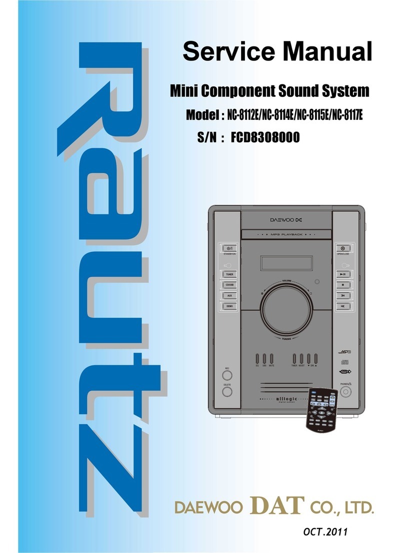
Daewoo NC-8011 User manual

Service Manual
MiniComponentSoundSystem
MAY.2010
00506
S/N : 9CD8308200

1
2
3
4
5
6
7
8
9
1
2
3
4
5
6
7
8
9
SAFETY PRECAUTIONS ......................................................................................... 1
TROUBLE SHOOTING GUIDE ................................................................................ 3
EXPLODED VIEW AND MECHANICAL PARTS LIST ............................................. 4
WIRING DIAGRAM ................................................................................................... 5
BLOCK DIAGRAM .................................................................................................... 6
SCHEMATIC DIAGRAM ........................................................................................... 7
FRONT&TUNER Section
MP3/CD Section
POWER Section (Only NC-8011DE Model)
P.C.B PATTERN LAYOUT.........................................................................................8
FRONT Section
MP3/CD Section
APPENDIX-ELECTRICAL PART LIST ...................................................................9
TableofContents
Mini component sound system
NC-8011/NC-8015/NC-8016DE
ADJUSTMENTS ........................................................................................................ 2
SMPS Section (Only NC-8015/8016DE Model)
TUNER Section
SMPS Section (Only NC-8015/8016DE Model)
MAIN Section (Only NC-8011DE Model)
MAIN Section (Only NC-8015/8016DE Model)
MAIN Section (Only NC-8011DE Model)
MAIN Section (Only NC-8015/8016DE Model)
POWER Section (Only NC-8011DE Model)

SafetyPrecautions
1
2
3
4
5
6
7
8
9
1
2
3
4
5
6
7
8
9

1
2
3
4
5
6
7
8
9
2
3
4
5
6
7
8
9
SafetyPrecautions
1

Adjustments
1
2
3
4
5
6
7
8
9
1
2
3
4
5
6
7
8
9
●TUNER Section
FM TEST EQUIPMENT
1.Adjust L003 to obtain 87MHz±0.5
2.Adjust PVC1(FM OSC)to obtain 108.5MHz±0.5
3.Adjust L002 to obtain maximal waveform for 90MHz
4.Adjust PVC2(FM ANT)to obtain maximal waveform for 106MHz
Item Input Circuit Setup Output Circuit Setup S.S.G setting Adjust point Adjustment
FM Frequency Connect output signal Connect V-Input signal 87MHz L003 Adjust for
Range Adjustment generator to FM ANT generator to CE002(-)/ Dev.26dB 87MHz±0.5
terminal of D001(-) CE003(-) pin 108.5MHz PVC1(FM OSC) Adjust for
5.0±zHM5.801Bd62.veDnip
FM RF Connect output signal Connect V-Input signal 90MHz L002 Adjust maximal
generator to FM ANT generator to CE002(-)/ Dev.26dB waveform for 90MHz
terminal of D001(-) CE003(-) pin 106MHz PVC2(FM ANT) Adjust maximal
zHM601rofmrofevawBd62.veDnip

Adjustments
1
2
3
4
5
6
7
8
9
1
2
3
4
5
6
7
8
9
●TUNER Section
AM TEST EQUIPMENT
1.Adjust L009 to obtain 510KHz±10(America)/513KHz±9(Europe)
2.Adjust PVC3(AM OSC)to obtain 1730KHz±20(America)/1638KHz±18(Europe).
3.Adjust L011 to obtain maximal waveform for 600KHz
4.Adjust PVC4(AM ANT)to obtain maximal waveform for 1400KHz
Item Input Circuit Setup Output Circuit Setup S.S.G setting Adjust point Adjustment
AM Frequency Connect output signal Connect V-Input signal 510KHz(America) L009 Adjust for
Range Adjustment generator to test loop generator to CE002(-)/ 513KHz(Europe) 510KHz±10(America)
)eporuE(9±zHK315Bd06.veDnip)-(300EC
1730KHz(America) PVC3(AM OSC) Adjust for
1638KHz(Europe) 1730KHz±20(America)
)eporuE(81±zHK8361Bd06.veD
AM RF Connect output signal Connect V-Input signal 600KHz L011 Adjust maximal
zHK006rofmrofevawBd06.veD/)-(200ECotrotarenegpooltsetotrotareneg
CE003(-) pin 1400KHz PVC4(AM ANT) Adjust maximal
zHK0041rofmrofevawBd06.veD
AM Antenna
AM
Antenna
Terminal
SET

MP3/CD Section
4
5
6
7
8
9
1
3
3
4
5
6
7
8
9
TroubleShootingGuide
1
3
3
CD open and disc insert Refer to 2
Spindle motor rotation
Pick-up unit return(outside >>
inside)
Laser diode on
Focusing operation
Read in CD/MP3 disc operation
Reading and auto play
CD play on
Refer to 3
Refer to 4
Refer to 5
Refer to 6
Auto to play
CD close and CD on
Refer to 1
AC cord in
Power ON/OFF ON
Reading in USB file and USB
Encoding operation Refer to 7

TroubleShootingGuide
9
MP3/CD Section
1
3
3
4
5
6
7
8
9
1
3
3
4
5
6
7
8
9
1. Pick-u
p
unit return
2. CD o
p
en and disc insert
3. Laser diode on
STOP PLAY
C 0V 1.8V
B 3.3V 2.1V
(HQ500) E 3.3V 2.8V
CD open and disc
insert
AC cord in
Function to CD
and Initializing
no
1. Check CN704
2. Check IC701 of 38pin and 39pin and 40pin
41pin and 44pin.
3. Check CN502,CW504.CN505
4. Check IC504 of 3pin:5.0V
5. Check Q501 collector:+3.3V
6. Check +3.3V (IC500 pin8/18/23/25/38/57/85
/113/116/122)
7. Check (IC502 SA5888 of 17pin and 18pin)SP+ 4.41V ,
SP- 3.41V
8. Check SPDO +1.90V (IC500 M5675 pin123)
9. Check (IC502 SA5888 of 12pin and 11pin) SL- 3.81V,
SL+ 3.91V
10. Check CD Board(Around IC solder short,cold soldering )
CD open and disc insert
Yes
Yes
CD close and cd on
Laser diode on
Yes
Focusing operation
no
1. Check +1.8V LD on(HQ500 collector)
2. Check +2.1V (HQ500 base pin) >>>in case
of play
B
E
C
no
Yes
Yes
Power ON/OFF ON no
1. Check CN505 of 5pin.
2. Check IC502 SA5888 of 10pin
no
1. Check CN505 of 3pin.
2. Check IC502 SA5888 of 9pin
*Only NC-8011DE
1.Check F980,F981
2.Check PT903
3.Check RF982,RF983
4.Check CN902,CW902
5.Check CW401 of 4pin(main power on)
6.Check IC900 of 3pin:9V
7.Check Q902 collector:9V
8.Check IC704 of 2pin:3.3V
9.Check IC701 of 22pin:3.3V
*Only NC-8015/8016DE
1.Check F901
2.Check PT901
3.Check CN902 of 6pin:5V
4.Check CN902 of 7pin:(main power on)
5.Check IC911 of 3pin:9V.
6.Check IC704 of 2pin:3.3V
7.Check IC701 of 22pin:3.3V

TroubleShootingGuide
MP3/CD Section
1
3
3
4
5
6
7
8
9
1
3
3
4
5
6
7
8
9
4. Focusing operation
5. Spindle motor rotation
6. Read in CD/MP3 disc operation
7. Read in USB file and USB Encoding operation
Focusing
operation
Yes
no
1. Check (IC502 SA5888 of 13pin and 14pin)
13pin 3.95V >>3.99V, pin18 3.72V >> 3.75V >>>
in case of play.
2. Check +1.58V(IC500 M5675 of 126pin).
Spindle motor
rotation
Yes
no 1. Check SPDO +1.90V(IC500 M5675 of 123Pin)
in case of play。
2. Check (IC502 SA5888 of 12pin and 11pin) SL- 3.81V,
SL+ 3.91V.
3. Check (IC502 SA5888 of 17pin and 18pin)SP+ 4.41V ,
SP- 3.41V
Read in CD/MP3
disc
Yes
no
Yes
1. Check CN704
2. Check IC701 of 38pin and 39pin and 40pin
41pin and 44pin.
3. Check CN502,CW504.CN505
4. Check IC504 of 3pin:5.0V
5. Check Q501 collector:+3.3V
6. Check +3.3V (IC500 pin8/18/23/25/38/57/85/113/116/122)
7. Check (IC502 SA5888 of 17pin and 18pin)SP+ 4.41V ,
SP- 3.41V
8. Check SPDO +1.90V (IC500 M5675 pin123)
9. Check (IC502 SA5888 of 12pin and 11pin) SL- 3.81V,
SL+ 3.91V
10. Check CD Board(Around IC solder short,cold soldering )
Yes
Read in USB file
operation
1. Check IC500(M5675) of 52pin and 53pin.
2. Check CW507,CN707.
3. Check J702.
no
USB Encoding no
1. Check IC500 (M5675) of 52pin and 53pin.
2. Check CN502 7pin 8pin and 9pin.
3. Check IC500(M5675) 40pin,43pin input signal.
4. Check IC500(M5675) 33pin,36pin output signal.

TroubleShootingGuide
1
3
3
4
5
6
7
8
9
1
Front &Tuner Section(only NC-8011DE Model)
3
3
4
5
6
7
8
9
Change to tuner function
AC cord in
Yes
Power ON/OFF ON
Yes
Yes
no
no
LCD Display and back
light
1.Check LC701
2.Check IC701
3.Check LD701 and LD702
4.Check X701(32.768KHZ)
Yes
Tuner LCD Display no
1.Check IC102 of 2pin Voltage:3.3V
2.Check IC700(CS9255)
3.Check Q002(S9018) and
Q003(S9018).
4.Check IC701 (CA6808F) of 40pin and
41pin.
5.Check X702(32.768KHZ)
Yes
Function command no
Yes
1.Check IC701 of 7pin /8pin /9pin/10pin/11pin
2.Check SW701/SW702/SW703/SW704/
SW705/SW706/SW707/SW708/SW709/
SW710/SW711/SW712/SW713/SW714
SW715/SW716/SW717/SW718/SW719.
1.Check F980,F981
2.Check PT903
3.Check RF982,RF983
4.Check CN902,CW902
5.Check CW401 of 4pin(main power on)
6.Check IC900 of 3pin:9V
7.Check Q902 collector:9V
8.Check IC704 of 2pin:3.3V
9.Check IC701 of 22pin:3.3V
Function LED light no 1.Check CN700 of 8pin:9V
2.Check LD705/LD706/LD707/LD709/
LD710/LD711/LD712/LD713/LD714/
LD715
Yes

TroubleShootingGuide
1
3
3
4
5
6
7
8
9
1
3
3
4
5
6
7
8
9
Front &Tuner Section(only NC-8011DE Model)
no
ST. LED on 1.Check IC101(TA2111N) of 11pin.
2.Check IC701(CA6808F) of 42pin
Yes
AM/FM Speaker sound no
1.Check AM ANT and CN001
2.FM ANT: CN003.
3.Check IC101 VCC 6pin: 4.7V.
4.Check PC101
5.Check L008 and L009.
6.Check output signal pin of IC101 of 13pin
and 14pin.
Change to CD function
no
1.Check CN704
2.Check IC701 of 38pin and 39pin and 40pin
41pin .
Yes
Yes
Phones sound
no
1.Check J701
2.Check IC702(IL4560D)
3.Check CN700

TroubleShootingGuide
1
3
3
4
5
6
7
8
9
1
Front &Tuner Section(only NC-8015/8016DE Model)
3
3
4
5
6
7
8
9
Change to tuner function
AC cord in
Yes
Power ON/OFF ON
Yes
Yes
no
no
LCD Display and back
light
1.Check LC701
2.Check IC701
3.Check LD701 and LD702
4.Check X701(32.768KHZ)
Yes
Tuner LCD Display no
1.Check IC102 of 2pin Voltage:3.3V
2.Check IC700(CS9255)
3.Check Q002(S9018) and
Q003(S9018).
4.Check IC701 (CA6808F) of 40pin and
41pin.
5.Check X702(32.768KHZ)
Yes
Function command no
Yes
1.Check IC701 of 7pin /8pin /9pin/10pin/11pin
2.Check SW701/SW702/SW703/SW704/
SW705/SW706/SW707/SW708/SW709/
SW710/SW711/SW712/SW713/SW714
SW715/SW716/SW717/SW718/SW719.
Function LED light no 1.Check CN700 of 10pin:5V
2.Check LD705/LD706/LD707/LD709/
LD710/LD711/LD712/LD713/LD714/
LD715
Yes
1.Check F901
2.Check PT901
3.Check CN902 of 6pin:5V
4.Check CN902 of 7pin:(main power on)
5.Check IC911 of 3pin:9V.
6.Check IC704 of 2pin:3.3V
7.Check IC701 of 22pin:3.3V

TroubleShootingGuide
1
3
3
4
5
6
7
8
9
1
3
3
4
5
6
7
8
9
Front &Tuner Section(only NC-8015/8016DE Model)
no
ST. LED on 1.Check IC101(TA2111N) of 11pin.
2.Check IC701(CA6808F) of 42pin
Yes
AM/FM Speaker sound no
1.Check AM ANT and CN001
2.FM ANT: CN003.
3.Check IC101 VCC 6pin: 4.7V.
4.Check PC101
5.Check L008 and L009.
6.Check output signal pin of IC101 of 13pin
and 14pin.
Change to CD function
no
1.Check CN704
2.Check IC701 of 38pin and 39pin and 40pin
41pin .
Yes
Yes
Phones sound
no
1.Check J701
2.Check IC702(IL4560D)
3.Check CN700

TroubleShootingGuide
POWER& Section
1
3
3
4
5
6
7
8
9
1
3
3
4
5
6
7
8
9
(only NC-8011DE Model)
AC cord in
no
Tuner/AUX/CD/USB Speaker
sound no
Phones sound no
Power ON/OFF ON
Yes
1.Check F980,F981
2.Check PT903
3.Check RF982,RF983
4.Check CN902,CW902
5.Check CW401 of 4pin(main power on)
6.Check IC900 of 3pin:9V
7.Check Q902 collector:9V
8.Check IC704 of 2pin:3.3V
9.Check IC701 of 22pin:3.3V
no
LCD Display and back
light
1.Check LC701
2.Check IC701
3.Check X701(32.768KHZ)
4.Check LD701 and LD702
1.Check J701
2.Check IC702(IL4560D)
3.Check CN700
Yes
Yes
1.Check IC800(CD7269ACZ):
Voltage of 3pin, 6pin and 1pin :more than DC
(18,-18V).
2.Check IC400(SC7314S):
Voltage of 1pin: normal DC(8.5V).
3.Check TUNER/AUX/CD input signal
4.Check output signal pin of IC800/( pin2,pin4).
5.Check output signal terminals(J800).
Yes

TroubleShootingGuide
SMPS& Section
1
3
3
4
5
6
7
8
9
1
3
3
4
5
6
7
8
9
(only NC-8015/8016DE Model)
AC cord in
no
Tuner/AUX/CD/USB Speaker
sound no
Phones sound no
Power ON/OFF ON
Yes 1.Check F901
2.Check PT901
3.Check CN902 of 6pin:5V
4.Check CN902 of 7pin:(main power on)
5.Check IC911 of 3pin:9V.
6.Check IC704 of 2pin:3.3V
7.Check IC701 of 22pin:3.3V
no
LCD Display and back
light
1.Check LC701
2.Check IC701
3.Check X701(32.768KHZ)
4.Check LD701 and LD702
1.Check J701
2.Check IC702(IL4560D)
3.Check CN700
Yes
Yes
1.Check PT902
2.Check IC800(TDA7498):
Voltage of 6pin and 13pin :30.5V(NC-8015DE)/
37.5V(NC-8016DE)
3.Check IC800(TDA7498):Voltage of 20pin and
21pin :3.3V
4.Check IC801(SA1117BH-3.3):Voltage of
2pin :3.3V
5.Check IC400(SC7314S):
Voltage of 1pin: normal DC(8.5V).
6.Check TUNER/AUX/CD input signal
7.Check output signal pin of IC800(TDA7498)
2/3pin, 8/9pin and 10/11pin,16/17pin.
8.Check output signal terminals(J800).
Yes


1
2
4
4
5
6
7
8
1
2
4
4
5
6
7
8
99
ExplodedViewandMechanicalParts List
No. PARTS NAME CODE NO. DESCRIPTIONS Q'TY REMARKS
1 PANEL FRONT 9CD0322500 HIPS 1
2 KNOB VR 9CD1370900 HIPS 1
3 KNOB TUNING 9CD1371000 HIPS 1
4 STOPPER 9CD5700700 HIPS 1
5 WINDOW LCD 9CD1628600 ACRYL 1
6 KNOB REC 9CD1371100 HIPS 1
7 KNOB FUNCTION 9CD1370800 HIPS 1
8 DECO FRONT L 9CD10195L0 HIPS 1
9 DECO FRONT R 9CD10195R0 HIPS 1
10 BRACKET CABINET 9CD2421200 SECC T1.0 2
11 REFLECTOR LED L 9CD22006L0 HIPS 1
12 REFLECTOR LED R 9CD22006R0 HIPS 1
13 CUSHION FOOT 9CD4212500 POPON MX-48HF Φ10*T3.0 2 NC-8015/16 4PCS
14 SHEET DIFFUSION 9CD9603100 PE 0.15T 1
15
WIDDOW REFLECTOR
9CD1621600 PMMA 1
16 GUIDE LCD 9CD2509500 HIPS WHITE 1
17 FRONT PCB AS FCDC00550X NC-8011/8015/8016DE 1
18 SCREW MACHINE 7003263511 M2.6X3.5 1
19 GEAR PVC 9CD2702600 ABS 1
20 PIN GEAR 9CD3501700 PW 1
21 GEAR IDLE 9CD2702700 ABS 1
22 TUNER PCB AS FCDC005700 NC-8011/8015/8016DE 1
23 NUT 7391500011 M5X0.8 1
24 USB & AUX PCB AS FCDC005510 NC-8011/8015/8016DE 1
25 AM ANT PCB AS FCDC005509 NC-8011/8015/8016DE 1
26 SW VOLTAGE SELE 5S30102377-1 ZH-06-01 1 ONLY FOR TOSHIBA
27 HEAT SINK 15 9CD4415500 AL T2.0 1 NC-8011DE
28 MAIN PCB AS FCDC00540X NC-8011 1
29 BRACKET HEAT TR 9CD2413901 STS T0.4 1
30 PLATE MICA 9CD0910600 WHITE MICA 25X30mm 1 NC-8011DE
31 POWER TRANS 5TP0066F78 EI=66X30 127V/230V 60/50Hz 1 NC-8011DE
No. PARTS NAME CODE NO. DESCRIPTIONS Q'TY REMARKS
32 CHASSIS BOTTOM 9CD0617900 HIPS 1
33 POWER PCB AS FCDC005000 NC-8011DE 1
34 CD (MP3) PCB AS FCDC005600 NC-8011/8015/8016DE 1
35 BRACKET CD DECK 9CD2421601 HIPS 1
36-1 CD- PICK UP 9CD6014830 R800 1 RICHLY
36-2 CD- PICK UP 9CD6014200 DA11VZ SANYO 1 SANYO
37 CD DECK 9CD6016800 8210D 1 ASA
38 COVER SIDE L 9CD04262L0 HIPS 1
39 COVER SIDE R 9CD04262R0 HIPS 1
40-1 COVER BACK 9CD0426100 HIPS 1 NC-8011DE
40-2 COVER BACK 9CD0426110 HIPS 1 NC-8015/16DE
41 COVER TOP 9CD0426000 HIPS 1
42 DOOR CD 9CD1819800 HIPS 1
43 AMP PCB AS FCDC00540X NC-8015/8016DE 1
44 HEAT SINK AMP 9CD4415610 AL EXT 1 NC-8015DE
45 SMPS PCB AS FCDC005800 NC-8015/8016DE 1
46 CHASSIS BOTTOM 9CD0618000 SECC T1.0 1 NC-8015/16DE
47 HEAT SINK AMP 9CD4415710 AL EXT 1 NC-8016DE
48 BRACKET PCB AMP 9CD2422400 HIPS 1 NC-8015/16DE
49 HOLDER AC CORD 9CD2303300 HIPS 1 NC-8015/16DE
50 SUPPORT PCB 12 9CD2507401 HIPS 3 NC-8015/16DE
51 AC CORD F736909021 2X0.75mm2 L=1.85M 1
52 SHIELD SMPS PCB 9CD3305600 SPTE T0.3 1
S1 SCREW TAPPTITE 7173261011 TT2 BIN 2.6X10 MFZN 20
S2 SCREW TAPPTITE 7173301011 TT2 BIN 3X10 MFZN 11
TOSHIBA 向13PCS
S3 SCREW TAPPTITE 7173300811 TT2 BIN 3X8 MFZN 4 NC-8015/16 13PCS
S4 SCREW WASHER 9CD3102400 TT2 WAS 3X10+D14 MFZN 3 NC-8011 4PCS
S5 SCREW TAPPTITE 7173301211 TT2 BIN 3X12 BK 23
S6 SCREW TAPPTITE 7173401211 TT2 BIN 4.0X12 MFZN 4 ONLY NC-8011DE
S7 SCREW TAPPTITE 7173301411 TT2 BIN 3X14 MFZN 3 ONLY NC-8015/8016DE

WiringDiagram
1
2
3
5
5
6
7
8
1
2
3
5
5
6
7
8
99
Only NC-8011DE Model

WiringDiagram
1
2
3
5
5
6
7
8
1
2
3
5
5
6
7
8
99
Only NC-8015/8016DE Model

1
2
3
4
5
6
7
8
1
2
3
4
6
6
7
8
99
Title
1
2
3
6
6
7
8
1
2
3
6
7
8
9
9
BlockDiagram
Only NC-8011DE Model
This manual suits for next models
2
Table of contents
Other Daewoo Stereo System manuals

Daewoo
Daewoo AMI-910L User manual

Daewoo
Daewoo XG-315 User manual

Daewoo
Daewoo MC?15UBW User manual

Daewoo
Daewoo AXG-322 User manual
Daewoo
Daewoo XG-332V User manual

Daewoo
Daewoo AMI-225M User manual

Daewoo
Daewoo XM-111 User manual

Daewoo
Daewoo AXL-122W User manual

Daewoo
Daewoo RG-361 User manual
Daewoo
Daewoo AXL-125 User manual

Daewoo
Daewoo AXW-118 User manual

Daewoo
Daewoo MC-5920SC User manual
Daewoo
Daewoo XD-615 User manual

Daewoo
Daewoo AMI-717L User manual
Daewoo
Daewoo DV - 115 User manual

Daewoo
Daewoo AMI-310 User manual

Daewoo
Daewoo AMI-917L User manual

Daewoo
Daewoo AMI-917L User manual

Daewoo
Daewoo XG-522 User manual

Daewoo
Daewoo Rautz NC-8008EB User manual