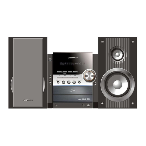
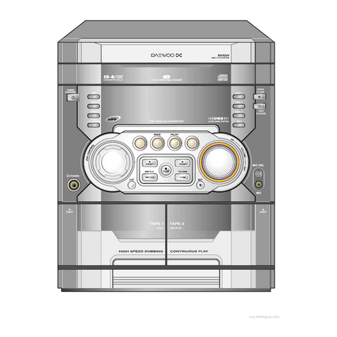
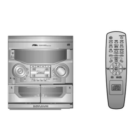
Daewoo NC-8112E User manual

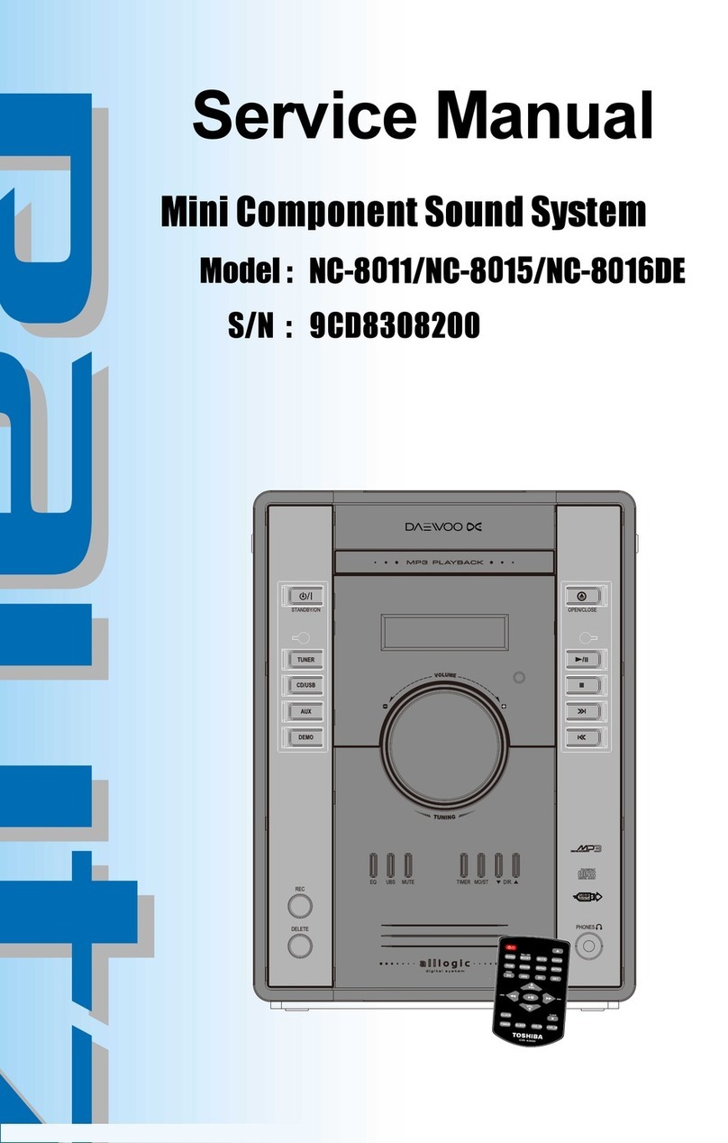
Service Manual
Mini Component Sound System
OCT.2011
NC-8112E/NC-8114E/NC-8115E/NC-8117E
S/N : FCD8308000

1
2
3
4
5
6
7
8
1
2
3
4
5
6
7
8
9
SAFETY PRECAUTIONS ......................................................................................... 1
TROUBLE SHOOTING GUIDE ................................................................................ 2
EXPLODED VIEW AND MECHANICAL PARTS LIST ............................................. 3
WIRING DIAGRAM ................................................................................................... 4
BLOCK DIAGRAM .................................................................................................... 5
SCHEMATIC DIAGRAM
...........................................................................................
6
FRONT&TUNER Section
MP3/CD Section
P.C.B PATTERN LAYOUT
.........................................................................................
7
FRONT Section
MP3/CD Section
APPENDIX-ELECTRICAL PART LIST ................................................................... 8
Table of Contents
Mini component sound system
NC-8112E/NC-8114E/NC-8115E/NC-8117E
SMPS Section
TUNER Section
SMPS Section
MAIN Section
MAIN Section

SafetyPrecautions
1
2
3
4
5
6
7
8
9
1
2
3
4
5
6
7
8
9

1
2
3
4
5
6
7
8
9
2
3
4
5
6
7
8
9
SafetyPrecautions
1

MP3/CD Section
4
5
6
7
8
9
1
2
3
4
5
6
7
8
9
Trouble Shooting Guide
1
2
3
CD open and disc insert Refer to 2
Spindle motor rotation
Pick-up unit return(outside >> inside)
and Rollette rotation
Laser diode on
Focusing operation
Read in CD/MP3 disc operation
Reading and auto play
CD play on
Refer to 3
Refer to 4
Refer to 5
Refer to 6
Auto to play
CD close and CD on
Refer to 1
AC cord in
Power ON/OFF ON
Reading in USB file and USB
Encoding operation Refer to 7

MP3/CD Section
4
5
6
7
8
9
1
2
3
4
5
6
7
8
9
Trouble Shooting Guide
1
2
3
1. Pick-up unit return
2. CD o
p
en and disc insert
3. Laser diode on
STOP PLAY
C 0V 1.8V
B 3.3V 2.1V
(HQ500) E 3.3V 2.8V
CD open and disc
insert
AC cord in
Function to CD
and Initializing CD no
1.Check CN704
2.Check IC707(MCU IC) of 23/24/25/26/27/28pin
3.Check IC705 of 5/12/13pin
4. Check CN502,CW504.CN505
5. Check IC504 of 3pin:5.0V
6. Check Q501 collector:+3.3V
7. Check +3.3V (IC500 pin8/18/23/25/38/57/85
/113/116/122)
8. Check (IC502 SA5888 of 17pin and 18pin)SP+ 4.41V ,
SP- 3.41V
9. Check SPDO +1.90V (IC500 M5675 pin123)
10. Check (IC502 SA5888 of 12pin and 11pin) SL- 3.81V,
SL+ 3.91V
11. Check CD Board(Around IC solder short,cold soldering )
CD open and disc insert
Yes
Yes
CD close and cd on
Laser diode on
Yes
Focusing operation
no
1. Check +1.8V LD on(HQ500 collector)
2. Check +2.1V (HQ500 base pin) >>>in case of play
B
E
C
no
Yes
Yes
Power ON/OFF ON no
1. Check CN505 of 5pin.
2. Check IC502 SA5888 of 10pin
no
1. Check CN505 of 3pin.
2. Check IC502 SA5888 of 9pin
1.Check CN700
2.Check IC701 of 33pin/40pin:3.3V
3..Check IC707(MCU IC) of 32pin:(main power on)

MP3/CD Section
4
5
6
7
8
9
1
2
3
4
5
6
7
8
9
Trouble Shooting Guide
1
2
3
4. Focusing operation
5. Spindle motor rotation
6. Read in CD/MP3 disc operation
7. Read in USB file and USB Encoding operation
Focusing
operation
Yes
no
1. Check (IC502 SA5888 of 13pin and 14pin)
13pin 3.95V >>3.99V, pin18 3.72V >> 3.75V >>>
in case of play.
2. Check +1.58V(IC500 M5675 of 126pin).
Spindle motor
rotation
Yes
no 1. Check SPDO +1.90V(IC500 M5675 of 123Pin)
in case of play。
2. Check (IC502 SA5888 of 12pin and 11pin) SL- 3.81V,
SL+ 3.91V.
3. Check (IC502 SA5888 of 17pin and 18pin)SP+ 4.41V ,
SP- 3.41V
Read in CD/MP3
disc
Yes
no
Yes
1.Check CN704
2.Check IC707(MCU IC) of 23/24/25/26/27/28pin
3.Check IC705 of 5/12/13pin
4. Check CN502,CW504.CN505
5. Check IC504 of 3pin:5.0V
6. Check Q501 collector:+3.3V
7. Check +3.3V (IC500 pin8/18/23/25/38/57/85/113/116/122)
8. Check (IC502 SA5888 of 17pin and 18pin)SP+ 4.41V ,
SP- 3.41V
9. Check SPDO +1.90V (IC500 M5675 pin123)
10. Check (IC502 SA5888 of 12pin and 11pin) SL- 3.81V,
SL+ 3.91V
11. Check CD Board(Around IC solder short,cold soldering )
Yes
Read in USB file
operation
1. Check IC500(M5675) of 52pin and 53pin.
2. Check CW507,CN707.
3. Check J702.
no
USB Encoding no
1. Check IC500 (M5675) of 52pin and 53pin.
2. Check CN502 7pin 8pin and 9pin.
3. Check IC500(M5675) 40pin,43pin input signal.
4. Check IC500(M5675) 33pin,36pin output signal.

Trouble Shooting Guide
1
2
3
4
5
6
7
8
9
1
Front & Tuner Section
2
3
4
5
6
7
8
9
AC cord in
Yes
Power ON/OFF ON
Yes
Yes
no
no
VFD Display
Function command no
Yes
1.Check IC707(MCU IC) of 44/45/46/47/48pin
2.Check SW701/SW702/SW703/SW704/
SW705/SW706/SW707/SW708/SW709/
SW710/SW711/SW712/SW713/SW714
SW715/SW716/SW717/SW718/SW719.
Function LED light no
1.Check CN700 of 10pin:5V
2.Check LD705/LD706/LD707/LD709/
LD710/LD711/LD712/LD713/LD714/
LD715
Yes
1.Check CN700
2.Check IC701 of 33pin/40pin:3.3V
3.Check IC707(MCU IC) of 32pin:(main power on)
1.Check CN702
2.Check FD701(VFD)
3.Check IC701(SC16315)

Trouble Shooting Guide
1
2
3
4
5
6
7
8
9
1
Front & Tuner Section
2
3
4
5
6
7
8
9
Change to tuner function no
1.Check IC707(MCU IC) of 27/28/31pin
2.Check CN703
3.Check CW703
4.Check IC105(TUNER IC)
5.Check X104(12MHZ)
Yes
Change to CD function
no
1.Check CN704
2.Check IC707(MCU IC) of 23/24/25/26/27/28pin
3.Check IC705 of 5/12/13pin
Yes
Phones sound
no
1.Check J301
2.Check IC702(IL4560D)
3.Check CN700

Trouble Shooting Guide
1
2
3
4
5
6
7
8
9
1
SMPS & AMP Section (Only NC-8112E Model)
2
3
4
5
6
7
8
9
AC cord in
no
Tuner/AUX/CD/USB Speaker
sound no
Phones sound no
Power ON/OFF ON
Yes 1.Check F901
2.Check PT901
3.Check CW902 of 6pin:3.3V
4.Check CW902 of 7pin:(main power on)
5.Check CN700
6.Check IC707(MCU IC)of 33pin/40pin:3.3V
7.Check IC707(MCU IC) of 32pin:(main power
on)
no
VFD Display
1.Check CW903
2.Check CN702
3.Check FD701(VFD)
4.Check IC701(SC16315)
1.Check J301
2.Check IC702(IL4560D)
3.Check CN700
Yes
Yes
1.Check CW901 of 1/2pin voltage:22V
2.Check CN801 of 1/2pin voltage:22V
3.Check IC800(TDA7492P): Voltage of 6/7pin
and 12/13pin :22V
4.Check IC800(TDA7492P):Voltage of 20pin and
21pin :3.3V
5.Check IC801(SA1117BH-3.3):Voltage of
2pin :3.3V
6.Check IC400(SC7314S):
Voltage of 1pin: normal DC(9V).
7.Check TUNER/AUX/CD input signal
8.Check output signal pin of IC800(TDA7492P)
2/3pin, 8/9pin and 10/11pin,16/17pin.
9.Check output signal terminals(J800).
Yes

Trouble Shooting Guide
1
2
3
4
5
6
7
8
9
1
SMPS & AMP Section (Only NC-8114E/NC-8115E Model)
2
3
4
5
6
7
8
9
AC cord in
no
Tuner/AUX/CD/USB Speaker
sound no
Phones sound no
Power ON/OFF ON
Yes 1.Check F901
2.Check PT901
3.Check CN902 of 6pin:3.3V
4.Check CN902 of 7pin:(main power on)
5.Check CN700
6.Check IC707(MCU IC)of 33pin/40pin:3.3V
7.Check IC707(MCU IC) of 32pin:(main power
on)
no
VFD Display
1.Check CW903
2.Check CN702
3.Check FD701(VFD)
4.Check IC701(SC16315)
1.Check J301
2.Check IC702(IL4560D)
3.Check CN700
Yes
Yes
1.Check CN901 of 1/2/3pin voltage:33.5V
2.Check CW801 of 1/2/3pin voltage:33.5V
3.Check IC800(TDA7498): Voltage of 6/7pin
and 12/13pin :33.5V
4.Check IC800(TDA7498):Voltage of 20pin and
21pin :3.3V
5.Check IC801(SA1117BH-3.3):Voltage of
2pin :3.3V
6.Check IC400(SC7314S):
Voltage of 1pin: normal DC(9V).
7.Check TUNER/AUX/CD input signal
8.Check output signal pin of IC800(TDA7492P)
2/3pin, 8/9pin and 10/11pin,16/17pin.
9.Check output signal terminals(J800).
Yes

Trouble Shooting Guide
1
2
3
4
5
6
7
8
9
1
SMPS & Section (Only NC-8117E Model)
2
3
4
5
6
7
8
9
START(AC cord ON)
1. SMPS Primary Part : Power Cord, Fuse, IC907,
PT901, IC905 Check.
2. SMPS Secondary Part : IC902, Q951~Q961
Check
yes
no
DISPLAY(DEMO) ?
yes 1. FRONT : Micom(IC707)
yes
no
yes
no
CD/USB ? no
Power On ? no
yes
Tuner ? no
AUX ? no
yes
Tuner(IC101)
AUX & Amp
CD & UBS
no
Remocon ?
yes
yes
Remocon batteries & Receiver(IC703)
R94FC5A control circuit Check
1. Front : VFD Driver(IC707), VFD(FD701) Check
yes
1. Front LEDs Check.
2. SMPS Secondary Part : IC902, Q951~Q961
Check

Trouble Shooting Guide
1
2
3
4
5
6
7
8
9
1
SMPS & section (Only NC-8117E Model)
2
3
4
5
6
7
8
9

Trouble Shooting Guide
1
2
3
4
5
6
7
8
9
1
SMPS & section (Only NC-8117E Model)
2
3
4
5
6
7
8
9

Trouble Shooting Guide
1
2
3
4
5
6
7
8
9
1
SMPS & section (Only NC-8117E Model)
2
3
4
5
6
7
8
9

Trouble Shooting Guide
1
2
3
4
5
6
7
8
9
1
SMPS & section (Only NC-8117E Model)
2
3
4
5
6
7
8
9

Trouble Shooting Guide
1
2
3
4
5
6
7
8
9
1
SMPS & section (Only NC-8117E Model)
2
3
4
5
6
7
8
9

Trouble Shooting Guide
1
2
3
4
5
6
7
8
9
1
SMPS & section (Only NC-8117E Model)
2
3
4
5
6
7
8
9

33

No. PARTS NAME CODE NO. DESCRIPTIONS Q'TY REMARKS No. PARTS NAME CODE NO. DESCRIPTIONS Q'TY REMARKS
21SPIH0053230DC9TNORFLENAP1 1SPIH0116240DC9KCABREVOC7
C821SPIH0190731DC9RVBONK2 1SPIH0006240DC9POTREVO
1
1
NC-8114E/NC-8115E
NC-8112E
FCD6501310
FCD6501250
MAIN PCB
MAIN PCB92
1SPIH0069101DC9GNIROCED3
17E118-CNFCD6501290MAIN PCB
03
1T2.1/)KNIPRAELC(AMMP40-0151074DC9DFVRETLIF4
NC-8114E
/NC-8115E
1TXELA0175144DC9PMAKNISTAEH
13
1LYRCA0068261DC9DCLWODNIW5
7E118-CN1TXELA0046144DC9PMAKNISTAEH
23
1SPIH0011731DC9CERBONK6
1NC-8114E/8115EFCD6501270BCPSPMS
1
NC-8112EFCD6501260BCPSPMS
33
1SPIH0080731DC9NOITCNUFBONK7
17E118-CNFCD6501280BCPSPMS
43
1SPIH0L59101DC9LTNORFOCED8
18.0TCCES0008160DC9MOTTOBSISSAHC
53
1SPIH0R59101DC9RTNORFOCED9
10 BRACKET CABINET9CD2421200SECC T1.0
1SPIH0042242DC9PMABCPTEKCARB
63
2
1SPIH0033032DC9DROCCAREDLOH
73
1SPIH0L60022DC9LDELROTCELFER11
1SPIH0R60022DC9RDELROTCELFER21
3SPIH1047052DC921BCPTROPPUS
83
39
13 CUSHION FOOT9CD4212500 POPON MX-48HF Φ
10*T3.0 4
1TXELA0082144DC91SKNISTAE
H
04
117SS11-ANH17SS11ANHDDFV41
1TXELA0144144DC9SPMSKNISTAEH
14
A5CF49R--A5CF49R1CMRCI51
7E118-CN1TXELA0121144DC91SKNISTAEH
24
1KCALBSBA0089052DC9DFVEDIUG61
7E118-CN1TXELA0095144DC9CISPMSKNISTAEH
34
44
45
1FCD6501240BCPTNORF71
82NZFM01X3NIB2TT1101033717ETITPPATWERCS1S
1SPIH0089181DC9DCROOD81
21NZFM8X3NIB2TT1180033717ETITPPATWERCS2S
1SPIH1061242DC9KCEDDCTEKCARB91
3NZFM41D+01X3SAW2TT0042013DC9REHSAWWE
RCS3S
1FCD6501040BCP)3PM(DC02
91KB01X3NIB2TT1101033717ETITPPATWERCS4S
1FCD6501241BCPXUA&BSU12
4KB21X3NIB2TT1121033717ETITPPATWERCS5S
1FCD6501300TUNER PCB22
3NZFM41X3NIB2TT1141033717ETITPPATWERCS6S
RVER BRIGHT
1EM101RNSFCD6014000PUKCIP-DC1-32
23-2 CD- PICK UP 9CD6014200DA11VZ SANYO 1 SANYO
ASA1D01280086106DC9KCEDDC42
1SPIH0L26240DC9LEDISREVOC52
1SPIH0R26240DC9REDISREVOC62
33
NC-8114E
/NC-8115E
NC-8114E
/NC-8115E
AC CORD F736909020 2X0.75mm2 L=1.85M 1 OPTION
This manual suits for next models
3
Table of contents
Other Daewoo Stereo System manuals

Daewoo
Daewoo NC-8011 User manual

Daewoo
Daewoo AXL-125 User manual

Daewoo
Daewoo MC-5911SC User manual

Daewoo
Daewoo AMI-716L User manual

Daewoo
Daewoo XM-111 User manual

Daewoo
Daewoo MC-5210SU User manual

Daewoo
Daewoo TR-951AUB User manual

Daewoo
Daewoo AXW-217 User manual

Daewoo
Daewoo AMI-208MC User manual

Daewoo
Daewoo AMI-V225M User manual

Daewoo
Daewoo AXL-128 User manual

Daewoo
Daewoo RH-433G User manual

Daewoo
Daewoo AMI-225M User manual

Daewoo
Daewoo AMI-917L User manual

Daewoo
Daewoo AXW-118 User manual

Daewoo
Daewoo MC-100UBM User manual

Daewoo
Daewoo XG-315 User manual

Daewoo
Daewoo AXG-322 User manual

Daewoo
Daewoo RH-4353GU Quick start guide

Daewoo
Daewoo AMI-310 User manual