Daihen varstroj VARMIG 211 BD Supermig User manual

N A V O D I L O Z A U P O R A B O
B E D I E N U N G S A N L E I T U N G
O P E R A T I N G I N S T R U C T I O N S
H A S Z N Á L A T I U T A S Í T Á S
U P U T S T V O Z A U P O R A B U
U P U T S T V O Z A U P O T R E B U
UPATSTVO ZA UPOTREBA
VARMIG 211 BD Supermig
VARMIG 251 BD Supermig
VARMIG 271 Supermig
VARMIG 331 Supermig
VARMIG 351 Supermig
DAIHEN VARSTROJ, varjenje
in rezanje ter robotizacija d.d
Industrijska ulica 4
SLO- 9220 Lendava
Tel:
fax:
E-mail:
url:
+ 386 (0)2 5788 820
+ 386 (0)2 5751 277
info@varstroj.si
http://www.varstroj.si
Prodaja:
Export:
Servis-tel:
Servis-fax:
+386 (0)2 5788 834, 835
+386 (0)2 5788 839, 840
+386 (0)2 5788 836, 879
+386 (0)2) 5751 646
SLIKA 1, BILD 1,
FIGURE 1, ÁBRA 1,
SLIKA 1, SLIKA 1
SLIKA 2, BILD 2,
FIGURE 2, ÁBRA 2,
SLIKA 2, SLIKA 2
SLIKA 3, BILD 3,
FIGURE 3, ÁBRA 3,
SLIKA 3, SLIKA 3
SLIKA 4, BILD 4,
FIGURE 4, ÁBRA 4,
SLIKA 4, SLIKA 4
SLO
D
GB
H
HR
SRB
BIH
MNE
MAK
Art.: 604947 v.2020.12

POMEMBNO
Ta navodila za uporabo so napisana za izkušene uporabnike. Pred uporabo aparata jih natančno
preberite. Če nimate dovolj znanja in izkušenj v zvezi s funkcijami in varno uporabo aparata, se
obrnite na našega strokovnjaka. Aparat lahko postavijo in vzdržujejo samo za to šolane osebe in
vsi, ki so ta navodila natančno prebrali in tudi razumeli. V primeru, da imate še vprašanja v zvezi s
postavitvijo ali uporabo, se obrnite na servisni oddelek proizvajalca.
OPOZORILO
Naprave za elektroobločno varjenje, ki so izdelek DAIHEN VARSTROJ, ustrezajo zahtevam standarda
ISO/ EN 60974-10 za elektromagnetno kompatibilnost (ta standard velja le za naprave za elktroobločno
varjenje). Uporabnik je dolžan napravo priključiti in uporabljati po navodilih proizvajalca. V primeru, da se
ugotovi, da varilna naprava povzroča elektromagnetne motnje, je uporabnik dolžan najti ustrezno tehnično
rešitev s pomočjo proizvajalca.
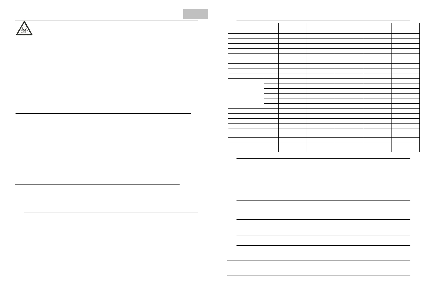
Napotki za ocenitev vpliva na okolico
Pred priključitvijo naprave mora uporabnik preveriti možne posledice elektromagnetnih motenj v
okolici in posebej paziti na:
Druge električne vodnike, telekomunikacijske vodnike, ki se nahajajo pod, nad ali poleg naprave
Avdio-vizualne naprave (radio, TV, itn…)
Računalnike in druge tehnične naprave
Varnostne naprave in sisteme
Zdravje prisotnih ljudi, npr. osebe s srčnimi spodbujevalniki, osebe s slušnimi aparati,…
Naprave za kalibriranje in merjenje
Na odpornost na motnje pri ostalih napravah v okolici. Uporabnik se mora prepričati, da so tudi
ostale naprave, ki se uporabljajo v okolici elektromagnetno kompatibilne, sicer so potrebni dodatni
zaščitni ukrepi.
Dele dneva, ko se uporablja varilna naprava
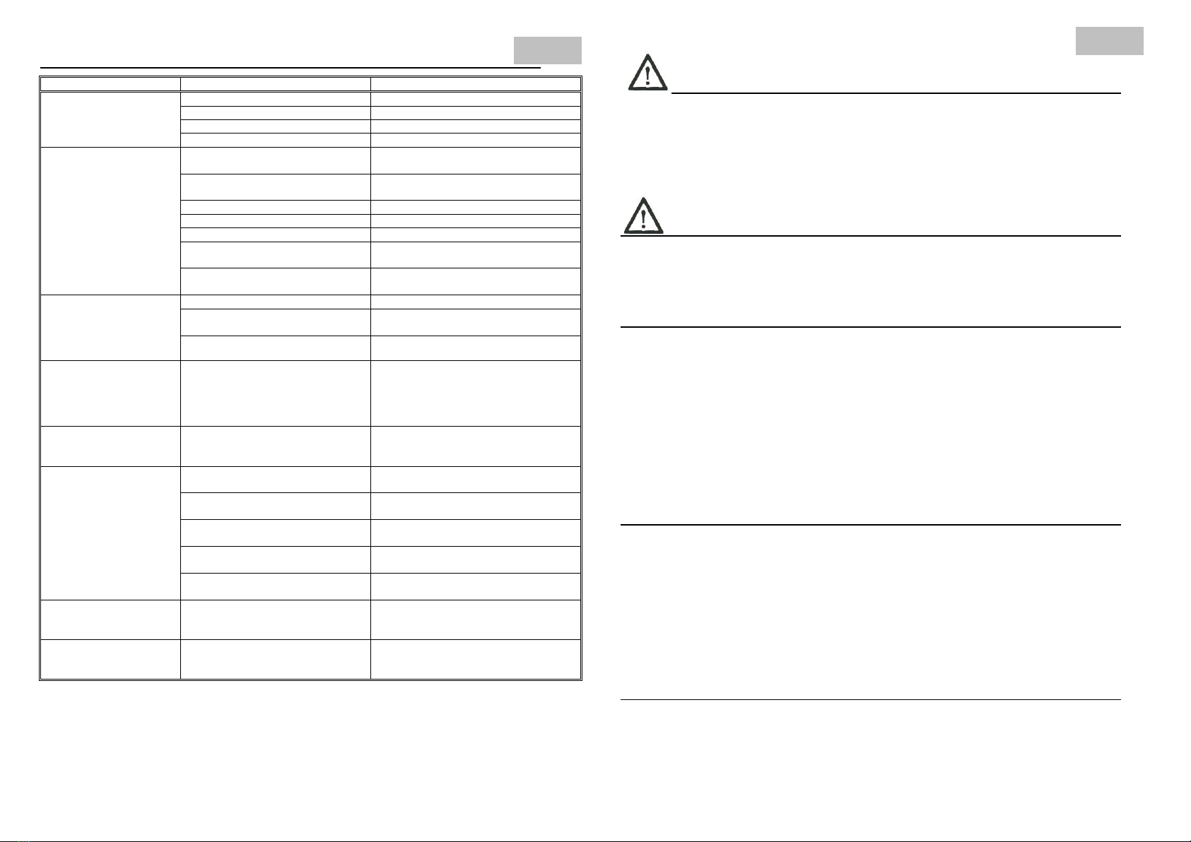
Priporočila za zmanjšanje vpliva na okolico
Vgradnja filtra na napajalni vodnik varilne naprave
Uporaba napajalnih kablov z zaščitnim opletom
Redno vzdrževanje varilne naprave
Ohišje varilnega aparata mora biti med uporabo zaprto (stranice in pokrovi morajo biti nameščeni in
privijačeni)
Varilni kabli morajo biti čim krajši
Ozemljitev varjenca
1. PREDPISI ZA PREPREČEVANJE NESREČ
Uporaba varilnih aparatov in varjenje samo ogroža uporabnikovo, in tudi zdravje drugih oseb.
Vsak uporabnik aparata mora zato brezpogojno prebrati in si zapomniti predpise za preprečevanje
nesreč. Radi bi Vas opozorili, da premišljena in strokovna uporaba aparata ob upoštevanju vseh
predpisov nudi največjo varnost proti vsem vrstam nesreč. Pri priključitvi in uporabi aparata je
potrebno upoštevati naslednje predpise:
1.1. Priključitev varilnega aparata
V ta namen upoštevajte naslednje:
1. Priključitev in vzdrževanje aparata se mora izvesti v skladu s predpisi za preprečevanje nesreč, ki
veljajo v uporabnikovi državi.
2. Stanje priključnega kabla in dovod do vtičnice preglejte in morebitne poškodbe odstranite.
Električne naprave preglejte v rednih presledkih. Uporabljajte kable z zadostnim presekom.
3. Kabel za maso pritrdite na varjenec čim bliže delovnemu območju. Njegova priključitev na nosilec
gradbene konstrukcije ali daleč od delovnega območja vodi do izgube energije in eventualno do
razelektrenja. Uporabljeni kabli ne smejo ležati v bližini verige, dvižne vrvi, električnih vodov ali jih
križati.
4. Izogibajte se uporabi aparata v mokrih prostorih. Okolica delovnega območja, kakor tudi drugi
aparati v njem in aparat sam, morajo biti suhi. Morebitno izlitje vode takoj odpravite. Ne škropite
aparata z vodo ali s kakšno drugo tekočino.
5. Preprečite direkten ročni dotik ali dotik mokrega oblačila s kovinskimi deli, ki so pod napetostjo.
Prepričajte se, da so rokavice in varnostna oblačila suha!
6. Pri delu v vlažnih prostorih ali na kovinski površini uporabljajte izolacijske rokavice in varnostne
čevlje (z gumijastim podplatom).
7. Aparat pri vsaki prekinitvi, tudi pri nenadnem izpadu elektrike, izklopite. Nenamerni masni kontakt
lahko povzroči nevarnost požara s pregretjem. Vklopljen aparat ne puščajte brez nadzora.
1.2 Zaščita oseb
S primernimi ukrepi je osebna zaščita varilca in tretjih oseb pred žarki (UV), hrupom, vročino in
plinskimi škodljivimi snovmi, nastalimi pri varjenju, zagotovljena. Ne izpostavljajte se brez maske
in primerne obleke vplivom obloka in žareče kovine. Varilna dela, ki se izvajajo brez upoštevanja
teh predpisov, lahko povzročijo resne zdravstvene posledice.
1. Nosite naslednjo zaščitno obleko: delovne rokavice - odporne proti ognju; debelo srajco z dolgimi
rokavi; dolge hlače brez zavihkov in visoke zaprte čevlje. To varuje kožo pred oblokom in pred
žarečo kovino. Razen tega je obvezna tudi uporaba kape ali čelade (za zaščito las).
2. Oči zavarujte z zaščitno masko z zadostno zaščitno stopnjo (vsaj NR10 ali višja). Ustrezno
velja za obraz, ušesa in vrat. Osebe, ki so v prostoru kjer se vari, je treba seznaniti s škodljivimi vplivi
varjenja na zdravje ljudi.
3. V delovnem območju nosite naušnike za zaščito pred hrupom, ki se širi pri varjenju.
4. Predvsem za ročno ali mehansko odstranjevanje žlindre so priporočena zaščitna očala s stranskimi
loputami. Žlindra je ponavadi zelo vroča in pri odbijanju daleč odleti. Pri tem je treba paziti tudi na
zaščito oseb v delovnem območju.
5. Varilno območje je potrebno zavarovati z negorečim zidom, saj lahko žarčenje, iskrice in žlindra
ogrožajo osebe v bližini. V neposredni bližini varilnega mesta ne sme biti lahko vnetljivih snovi,
hlapljivih tekočin ali plinov. Prostor v katerem varimo naj ima odsesovalne in/ali prezračevalne
naprave za odvajanje varilnih plinov.
1.3 Preprečevanje požara in žlindre
Žareča žlindra in iskrice (pršeča talina) predstavljajo požarne vzroke. Požare
in eksplozije lahko preprečimo, če se držimo naslednjih predpisov:
Odstranite vnetljive predmete oz. jih pokrijte z negorljivim materialom. K tem vnetljivim
predmetom spadajo: les, žagovina, oblačila, laki in topila, bencin, kurilno olje, zemeljski plin,
acetilen, propan in podobne vnetljive snovi.
1. Tudi po tem, ko se zbiralniki in vodi temeljito izpraznijo, je previdnost pri varjenju zelo priporočena.
2. Za preprečevanje požarov imejte pripravljeno gasilno opremo, npr. gasilni aparat, vodo, pesek, itd.
3. Ne varite ali režite na zaprtih posodah ali cevnih vodih.
4. Ne varite na odprtih posodah ali cevnih vodih, ki še vsebujejo snovi ali ostanke, ki pod vplivom
visokih temperatur predstavljajo požarno nevarnost.
SLO

1.4 Nevarnost zastrupitve
Pri varjenju sproščeni plini in dim so zdravju škodljivi, če se dalj časa vdihavajo. Zato
upoštevajte naslednje predpise:
1. Poskrbite za zadostno prezračevanje v delovnem prostoru.
2. Pri obdelavi snovi, kot so svinec, berilij, kadmij, cink, kakor tudi pocinkani in lakirani varjenci, morate
imeti prisilno prezračevanje. Varilec mora imeti zaščitena dihala.
3. Vsepovsod, kjer je dovod zraka nezadosten, morate delati z dihalno masko in dovajanjem svežega
zraka.
4. Kot osnovno pravilo velja, da mora biti varilec pri varjenju v ozkih prostorih (v kotlih, v jarkih, itd.) z
zunaj nahajajočo osebo zavarovan. Glede na to se morajo upoštevati vsi predpisi za preprečevanje
nesreč.
5. Ne varite v bližini prostorov, kjer se razmaščuje ali lakira. Tam se lahko (zaradi teh obdelav) razvijajo
kloro-ogljiko-vodikove pare, ki se pod vplivom vročine in žarčenja obloka pretvorijo v fosgen, skrajno
strupen plin.
6. Znaki za pomanjkljivo prezračevanje in hkrati simptomi zastrupitve so draženje oči, nosa in žrela. V
tem primeru prekinite delo in delovni prostor dobro prezračite. Če neprijetno počutje traja dalj časa,
končajte z varjenjem.
1.5 Postavitev varilnega aparata
Pri postavitvi aparata upoštevajte naslednje predpise:
1. Uporabnik mora imeti enostaven pristop k stikalom in priključkom aparata.
2. Aparata ne postavljajte v ozkih prostorih, ker mora imeti varilni izvor zadostno prezračevanje.
Izognite se prašnim ali onesnaženim prostorom, saj lahko aparat vsesa tujke.
3. Aparat (vključno s kabli) ne sme ovirati prehoda ali delovno sposobnost drugih oseb.
4. Aparat mora biti zavarovan, da se ne prevrne ali pade po tleh.
5. Vsaka postavitev na višje mesto skriva nevarnost, da aparat pade po tleh.
1.6 Prevoz varilnega aparata
Aparat je izdelan za pomikanje in prevoz.
Če se upoštevajo naslednji predpisi je prevoz enostaven:
1. Aparat se lahko pomika z ročajem, ki je vgrajen in se tako vleče oz. potiska po vgrajenih kolesih.
2. Pred transportom izvlecite vtikač iz omrežne vtičnice in odstranite priključene kable.
3. Aparat se ne sme dvigniti za kabel ali zanj vleči po tleh.
1.7. Delovno okolje
Varilni aparat ni namenjen za delo v kopalnicah, tuših, bazenih in podobnih okoljih. V primeru dela v
takšnem okolju je potrebno paziti, da vodovodne pipe pravilno zaprta in se prepričajte, da prostora nihče
ne uporablja za njihovo delovanje.
Varilni aparat ni primeren za uporabo in skladiščenje v dežju in snegu
2. OPIS APARATA
Varilni aparat VARMIG Supermig je polavtomatski aparat za elektroobločno varjenje v zaščitni atmosferi
plinov. Kot zaščitni plin lahko uporabimo mešanico (Ar82% - CO2 18%), čisti argon ali CO2, v odvisnosti
od vrste materiala. Aparati so namenjeni za varjenje pločevin, pri raznih popravilih, v avtomobilskih
delavnicah, v proizvodnji, industriji, itd. Zaradi relativno visoke intermitence so aparati primerni tudi za
težja in zahtevnejša dela, kjer je intenzivnost varjenja visoka (glej parametre na napisni ploščici aparata).
Naprave so glede zanesljivosti in varnosti pri delu zgrajeni tako, da zadovoljujejo vse osnovne zahteve v
moderni tehnologiji varjenja.
Prednosti varjenja po postopku MIG/MAG z aparati VARMIG Supermig:
racionalnejše varjenje, manjši stroški ob veliki hitrosti varjenja in širokem področju uporabe
enostavno rokovanje
možnost natančne izbire parametrov
odlična kakovost zvara (homogena struktura z gladkim korenom zvara in velika trdnost)
enostavno in lahko vzdrževanje ter servisiranje
možnost točkovnega varjenja
možnost intervalnega varjenja
3. TEHNIČNI PODATKI (ISO/ EN 60974-1)
Varmig 211BD
Supermig
Varmig 251BD
Supermig
Varmig 271
Supermig
Varmig 331
Supermig
Varmig 351
Supermig
Priključna napetost
3x400V/50Hz
3x400V/50Hz
3x400V/50Hz
3x400V/50Hz
3x400V/50Hz
Max. priključna moč
8,3 kVA
11,1 kVA
13,2 kVA
14,0 kVA
18,1 kVA
Varovalka (počasna)
16 AT
16 AT
16 AT
20 AT
20/25 AT
Napetost praznega teka
16,5 –34,7 V
17 –41V
17,6 –42,5
17,6 –42,3V
18,5 –48,2V
Poraba v stanju
pripravljenosti
30 W
49 W
49 W
49 W
80 W
Izkoristek
71.8 %
76.8 %
74%
79,1%
78.8 %
Varilni tok
15 –200 A
25 –250 A
30 –265 A
30 –300 A
40 –350 A
Varilna napetost
14,8 –24,0 V
15,25 –26,5V
15,5 –27,3 V
15,5 –29 V
16 –31,5 V
ED
20%
200 A
250 A
265 A
30%
300 A
35%
40%
350 A
60%
130 A
168 A
160 A
210 A
285 A
100%
100 A
130 A
130 A
165 A
220 A
Regulacija varilnega toka
10 st.
10 st.
10 st.
2 x 10 st.
3 x 10 st.
Čas točkovnega varjenja
0,2 –2,5 s
0,2 –2,5 s
0,2 –2,5 s
0,2 –2,5 s
0,2 –2,5 s
Čas intervala (pavze)
0,2 –2,5 s
0,2 –2,5 s
0,2 –2,5 s
0,2 –2,5 s
0,2 –2,5 s
Premer varilne žice Ø
0,6 –1,0 mm
0,6 –1,2 mm
0,6 –1,2 mm
0,6 –1,2 mm
0,6 –1,2 mm
Razred zaščite
IP21s
IP21s
IP21s
IP21s
IP21s
Razred izolacije
H
H
H
H
H
Hlajenje
Ventilator
Ventilator
Ventilator
Ventilator
Ventilator
Teža
63 kg
66 kg
76 kg
88 kg
92 kg
Dimenzije DxŠxV (mm)
750x440x640
750x440x640
850x540x780
850x540x780
850x540x780
4. ZGRADBA NAPRAVE
Varilni polavtomati Varmig Supermig so izdelani v kompaktni izvedbi, majhnih dimenzij z veliko mobilnostjo.
Primerni so za delo v majhnem prostoru, v težjih pogojih dela, kjer se zahteva pogosto premikanje naprave.
Odvisni so samo od priključnega kabla napajalne napetosti iz omrežja, ki se nahaja na zadnji stranici. Kolut z
varilno žico ter naprava za podajanje le-te sta nameščeni v ohišju naprave za vrati na stranici. Pristop do njiju je
mogoč z odpiranjem teh vrat. Jeklenka (max 20l) z zaščitnim plinom se namesti na podaljšanem dnu nad
zadnjimi kolesi naprave. Na sprednji strani naprave so nameščeni vsi krmilni elementi, potrebni za vklop, izbiro
varilnega toka, hitrost podajanja varilne žice, elementi za signalizacijo, centralni priključek za cevni paket z
varilno pištolo oz. gorilnikom ter priključek za maso. Na zadnji stranici je nameščen priključek za zaščitni plin.
4.1 Ohišje polavtomatov VARMIG Supermig
Izdelano je iz visokokakovostnega materiala, je sodobno oblikovano in zgrajeno tako, da se brez težav lahko
odpirajo in snamejo stranice, kar omogoča enostavno vzdrževanje in servisiranje. Na sprednjem delu ohišja sta
nameščena ročaj, na spodnjem pa kolesa, kar omogoča enostavno premikanje aparata.
4.2 Energetski transformator
Je trifazne oblike, razreda izolacije H (primarno in sekundarno navitje je galvansko ločeno s pregrado
zaradi varnosti. Navitje je bakreno, izvedeno z odcepi.)
4.3 Usmerniški stavek
Sestavljen je iz hladilnega telesa, v katero so stisnjene diode. Služi za usmerjanje varilnega toka in napetosti).
4.4 Dušilka (271, 331, 351 Supermig)
Močno vpliva na kvaliteto varjenja s kratkim oblokom in pri varjenju aluminija. Zgrajena je tako, da ima kar
največje delovanje (dušenje) na spremembe (nihanje) frekvence kratkega stika obloka.
4.5 Elektronski vložek
Služi za vklop krmilnih elementov, elektromotorja za dodajanje varilne žice in nastavitev hitrosti varilne žice ter za
točkovno varjenje.
4.6 Motor z mehanizmom za dodajanje varilne žice
Je enosmerni, kompaktne oblike. Mehanizem podaja žico preko pogonskega kolesa, ki je nameščeno na gredi
reduktorja in pritiska kolo. Silo pritiskanja pritisnega kolesa na varilno žico in pogonsko kolo nastavljamo preko
vzmeti z vijakom.
SLO

5. Prikaz in opis funkcij varilnega aparata Varmig 211BD, 251BD,271, 331,351 Supermig
SLIKA 5: Plošča čelna Varmig 331 Supermig
Poz.
Naziv elementa
Funkcija
Varmig
211BD,251BD,271
Supermig
Varmig
331, 351
Supermig
01
Stikalo preklopno
Stikalo za vklop aparata
•
•
02
Stikalo stopenjsko
Groba regulacija napetosti (toka)
varjenja
•
03
Stikalo stopenjsko
Regulacija napetosti (toka) varjenja
•
•
04
Preklopnik za
izbiro načina
varjenja
Izbira načina varjenja:
2–Taktno ()
4–Taktno ()
Točkovno varjenje (●●●●)
intervalno varjenje ( )
Uvajanje žice ( )
•
•
05
Potenciometer
Nastavljanje hitrosti dodajanja žice
•
•
06
Potenciometer
Nastavljanje časa točkanja:
nastavljanje časa 0,2–2,5 s
•
•
07
Potenciometer
Nastavljanje časa točkanja:
Nastavljanje časa 0,2–2,5 s
•
•
08
LED Dioda -
Oranžna
Prikaz vklopa termozaščite.
Dodatno: prikaz napak glej. tč.5.9
•
•
Softstart
•
•
Avtomatsko odgorevanje
•
•
5.1. Nastavitev varilnega toka
Varilni tok nastavljamo stopenjsko. Velikost varilnega toka izbiramo tako, da ročico stikala za nastavljanje
jakosti varilnega toka vrtimo v levo ali desno, in sicer:
vrtenje v levo –manjši varilni tok
vrtenje v desno –večji varilni tok
5.2 2T (2-taktno delovanje)
Na preklopniku na čelni plošči aparata nastavimo nastavimo 2-taktno delovanje (položaj 1). Pritisnemo
tipko START in jo držimo. Aparat začne z varjenjem. Spustimo tipko START in varjenje aparata se ustavi.
5.3 4T (4-taktno delovanje)
Na preklopniku na čelni plošči aparata nastavimo nastavimo 4-taktno delovanje (položaj 2). Pritisnemo
tipko START in jo spustimo. Aparat začne z varjenjem. Za konec varjenja ponovno pritisnemo tipko
START in jo spustimo. Varjenje aparata se ustavi.
5.4. Točkovno varjenje s polavtomatom
V kolikor želimo z aparatom variti kratke zvare vklopimo stikalo na potenciometru (sl.5/poz.4) in nastavimo
čas točkanja, ki je nastavljiv med 0,5 sek. in 2,5 sek. Ostale parametre varjenja nastavimo po opisanem
postopku v poglavju 7.1. Navadno plinsko šobo zamenjamo s šobo za točkanje in varimo. Po preteku
nastavljenega časa točkanja se aparat samodejno izklopi.
Naslednji zvar lahko izvedemo s spustom in ponovnim pritiskom tipkala na varilni pištoli.
ČAS TOČKANJA min 0,2 sec ----- max 2,5 sec
5.5 Intervalno varjenje s polavtomatom –potenciometer (položaj 4)*
Če želimo zaporedno variti več kratkih zvarov, preklopnik na čelni plošči aparata nastavimo na položaj 4 –
intervalno varjenje in nastavimo čas točkanja, čas pavze in hitrost žice. Čas je nastavljiv med 0,2 sek. in
2,5 sek. Za intervalno varjenje nastavimo čas varjenja in čas pavze in ustrezno hitrost dodajanja žice
(začetni položaj je sredinski položaj potenciometrov). Ob pritisku tipkala na pištoli se začne intervalno
varjenje s presledki. V času pavze ostane zaščitni plin prisoten in kontaktor vklopljen, motor za dodajanje
žice pa je zaprt. Pri tem moramo ves čas intervalnega varjenja pritiskati/držati tipkalo na varilni pištoli.
ČAS TOČKANJA min 0,2 sec ----- max 2,5 sec
ČAS INTERVALA min 0,2 sec ----- max 2,5 sec
*samo za varjenje jekla
5.6 Uvajanje žice
Preklopnik nastavimo na uvajanje žice (položaj 5). Motor se vrti takoj, ko smo preklopili preklopnik z
hitrostjo nastavljeno z potenciometrom HITROST ZICE.
5.7 Avtomatski softstart
Elektronika samodejno doda softstart glede na hitrost dodajanja žice. Pri minimalni hitrosti softstata ni.
5.8Avtomatsko odgorevanje
Elektronika samodejno doda odgorevanje glede na izbrano hitrost dodajanja žice.
SLO

5.9 Seznam prikaza napak delovanja varilnega aparata
Prikaz napak je izveden z različnim utripanjem RUMENE LED DIODE (LED dioda: - sl.5, poz.8)
Prikaz napake
Opis in odprava napake -
LED SVETI:
Pregretje.
Aparat se je zaradi intenzivnega dela pregrel.
Počakamo da se aparat ohladi.
MED HLAJENJEM NE IZKLAPLJAJ APARATA!
LED UTRIPA
(v enakomernih presledkih):
Stekel je prevelik tok pogona varilne žice. Oviran je
transport varilne žice.
Pregledati (zamenjati,očistiti) celotno pot varilne žice=>
glej poglavje 11. tega navodila
Po ugasnitvi opozorilnega izpisa (ca.15 sek.) lahko
nadaljujemo z delom. (ni potrebno izklopiti aparata)
LED UTRIPA
(2 utripa-daljša pavza...):
Aparat je varnostno ustavil delovanje aparata
zaradi aktivirane tipke start (na gorilniku). Pojavi se pri
aktivirani tipki (npr. napačno odložena varilna pištola)
ob vklopu aparata, aktivirani tipki po končani
temperaturni preobremenitvi ali preobremenitvi
motorja.
6. PRIKLJUČITEV IN PRIPRAVA
6.1 Priključitev aparata na omrežno napetost
Varilni aparat Varmig 211BD, 251BD, 271, 331 in 351 Supermig je grajen za trifazno omrežno napetost
3x400V/50Hz, in varovan s počasnimi varovalkami. Postavimo ga na primerno mesto blizu mesta varjenja
in omogočimo nemoten dostop zraka. Ni priporočljivo postavljati aparata v bližino predmetov, ki sevajo
toploto in na kraj, kjer ni zaščite pred atmosferskimi vplivi.
Pri vsakokratnem priključevanju aparata na omrežje mora biti vklopno stikalo v položaju »0«.
6.2 Jeklenka z zaščitnim plinom
Jeklenko z zaščitnim plinom postavimo na podaljšano dno in jo zavarujemo pred prevrnitvijo z verigo.
Odvijemo zaščitni pokrov in ventil jeklenke počasi odpiramo, da izpihnemo morebitne nečistoče. Pri
uporabi ogljikovega dioksida (CO2) lahko pride do nastanka ledu na reducirnem ventilu, kar lahko
preprečimo z uporabo grelca (opcija). Na jeklenko montiramo reducirni ventil z manometri in ga spojimo z
armirano cevjo na plinski ventil. Vijak za nastavitev količine plina obrnemo v levo – najmanjši tlak.
Odpremo plinski ventil na jeklenki in vijak za nastavitev količine plina obračamo v desno tako dolgo, da
kazalec na manometru pokaže želeni tlak plina.
6.3 - Cevni paket z varilno pištolo –varilni gorilnik (glej prilogo) in kabel za maso
Cevni paket z varilno pištolo vstavimo v centralni priključek. Nato obračamo plastično matico v desno tako
dolgo, dokler ne začutimo odpora. A tem je cevi paket montiran na svoje mesto. Kabel s masno stezalko
dobro pričvrstimo na varjenec, da se spojno mesto ne bo grelo, kar povzroča slabšo kvaliteto zvara.
6.4 Kolut z varilno žico
Preden namestimo kolut, moramo z vijakom za nastavitev zaviralnega momenta, ki se nahaja na nosilcu
koluta prilagoditi pritisk zaviranja. Ta je pravilno naravnan, če se z blagim potegom žice kolut lahko
obrača. Zaviranje ne sme biti premočno, ker bomo nepotrebno obremenjevali pogonski motor. Pri
nameščanju koluta na nosilec moramo paziti na pravilno smer odvijanja varilne žice (v desno).
6.5 Napeljava varilne žice
Cev za vodenje elektrode (varilne žice) je občutljiva na mehansko obrabo, zato je potrebno žico pred
napeljavo na koncu popiliti in zaobliti. Z obračanjem v levo popustimo vzmet, nemeščeno na vijaku.
Preverimo, ali utor na pogonskem valju ustreza premeru žice. V kolikor ne, ga zamenjamo. Žico
izravnamo ter jo nato potisnemo v cevko in v spiralno vodilo cevnega paketa. Vijak za regulacijo pritiska
transportnih sredstev koles obračamo v smeri urinega kazalca dokler ne dosežemo pravilen pritisk.
Dodatno: glej 5.6.
7. UPRAVLJANJE APARATA
Vključimo stikalo (sl.5/poz.1) in zasveti signalna lučka. Potenciometer za nastavljanje hitrosti podajanje
varilne žice nastavimo srednji položaj. S pritiskom tipkala na varilni pištoli vklopimo plinski ventil in
elektromotor za pogon varilne žice. Če je plin na jeklenki odprt, bo na izhodu varilne pištole izhajal plin.
Če vijak za regulacijo pritiska koles ni dovolj zategnjen, se bodo kolesa obračala, vendar žice ne bodo
potiskali. V tem primeru ga moramo narahlo zategniti v smeri urinega kazalca. Nikoli ne smemo vijak
preveč zategniti, ker nepotrebno obremenimo motor, ležaje na kolesih in povečamo obrabo utorov
pogonskih koles. Odpustimo tipkalo na varilni pištoli ter snamemo zaščitno plinsko šobo. Preverimo, če
kontaktna šoba ustreza premeru žice. Pri vstavljanju žice se pogosto v primeru slabe zaoblitve vrha
varilne žice le – ta zatakne na izhodu skozi njo, zato jo je dobro sneti. Ponovno pritisnemo tipkalo na
varilni pištoli in hitrost žice nastavimo tako, da elektromotor nemoteno dodaja varilno žico, dokler se ta ne
pojavi na izhodu varilne pištole. Nato privijemo kontaktno in plinsko šobo in glede na vrsto materiala, ki ga
varimo, nastavimo varilne parametre. Po tem vršimo regulacijo varilnega toka s stikalom za nastavitev
toka, regulacijo hitrosti dodajanja varilne žice ter naredimo poskusni zvar.
Aparat ima vgrajeno termično zaščito . Ko termostat izklopi, zasveti oranžna lučka (sl.5/poz.8)., kar
pomeni, da z aparatom ni možno variti. Ko se aparat ohladi, lučka ugasne, nakar lahko ponovno varimo.
POZOR: Med hlajenjem ne izklapljajte aparata!
Vodenje varilne pištole ima velik vpliv na obliko temena zvara.
KONTAKTNA
ŠOBA
POTISNI PRAVOKOTNI VLEČNI
POLOŽAJ POLOŽAJ POLOŽAJ NAČINI POMIKANJA
MIG/MAG GORILNIKA
7.1 Varjenje s polavtomatom
Razdalja med kontaktno šobo in varjencem mora biti med varjenjem konstantna. Priporočljiva razdalja
med kontaktno šobo in varjencem za konstrukcijska in nerjaveča jekla je 5 – 10 mm, za aluminij pa 20
mm.
Če so vsi varilni parametri pravilno nastavljeni, dobimo najkvalitetnejši zvar. Če spustimo tipkalo na varilni
pištoli, izklopimo elektromotor, energetski transformator in s tem prekinemo električni oblok. Zaščitni plin
bo še kratek čas izhajal, da zaščitimo zvarjeno mesto pred oksidacijo.
7.2. Varjenje aluminija
Pri varjenju aluminija uporabimo kot zaščitni plin čisti Argon. Na pogonskem mehanizmu moramo zamenjati
pogonsko kolo z " V " utorom s kolesom z " U " utorom..
SLO

8. VZDRŽEVANJE
DNEVNO:
1. Pri vsaki menjavi koluta žice je potrebno preveriti ali žica nemoteno potuje znotraj mehanizma za
dodajanje žice in skozi spiralno vodilo.
2. Izpihati spiralno vodilo.
3. Očistiti žlindro znotraj plinske šobe z zagozdo iz lesa ali plastike. Nastale žlindre se brez težav
odstranijo, če predhodno poškropimo plinsko šobo z topilom na bazi silikona ali podobno.
4. Pregledati šobo za vodenje varilne žice; s talnim vlekom žice se odprtina razširi. Če je prevelika, je
kontakt slab in nastaja nemiren električni oblok.
5. Pregledati reducirni ventil in preveriti ali teče skozenj želena količina plina.
TEDENSKO:
1. Pregledati primarni kabel z vtičem, če so kontakti zrahljani, je to pogosto vzrok motenj v varjenju.
2. Pregledati brezhibnost spoja masa kabla s stezalko.
3. Očistiti valje za pomik žice, utor ter odprtino za pomik žice.
NA 6 MESECEV:
1. Izvor varilnega toka: sneti pokrov in stransko stranico ter izpihati notranjost polavtomata s
kromprimiranim zrakom.
2. Priključke za varjenje očistiti z brusnim platnom. Zaščitne kontakte naj pregleduje za to usposobljena
oseba.
3. Pred vsakim odpiranjem ohišja aparata priključni kabel obvezno galvansko ločiti od napajalnega
omrežja. Odkrivanje in odpravljanje napak naj opravlja le za to usposobljena in pooblaščena oseba.
Pri samem vzdrževalnem delu je potrebno upoštevati:
občasno je potrebno izpihati aparat s komprimiranim zrakom,
enkrat letno prekontrolirati spoje kablov s sekundarnim navitjem ter spoj zaščitnega vodnika.
Čas zagotavljanja servisiranja je doba v kateri vam zagotavljamo servis, pribor in nadomestne dele, ki so
potrebni za normalno uporabo proizvoda. Čas zagotavljana servisiranja je 7 let ter se prične šteti z dnem
nakupa proizvoda.
9. GARANCIJA IN SERVIS
Glej garancijski list.
10. SEZNAM REZERVNIH DELOV
Slika
Poz
Naziv dela
Varmig
211 BD
Supermig
Varmig
251 BD
Supermig
Varmig
271
Supermig
Varmig
331
Supermig
Varmig
351
Supermig
Opombe
1
1
Stikalo vklopno
015172
015172
015172
015172
015172
1
2
Stikalo stopenjsko 1-2
601507
1
2
Stikalo stopenjsko 1-2-3
600830
1
3
Stikalo stopenjsko 1-10
015309
015309
015309
015309
600829
1
5
Vložek elektronski MK 42 DI
603131
603131
603131
603131
603131
1
6
Gumb potenciometra
690229
690229
690229
690229
690229
1
6a
Pokrov gumba FI23
690230
690230
690230
690230
690230
1
7
Priključek centralni kpl.
603430
603430
603430
603430
603430
1
07a
Cevka
603431
603431
603431
603431
603431
1
8
Vtičnica komplet
691051
691051
675895
675895
675895
1
9
Kolo 160
680607
680607
1
9
Kolo 200
676020
676020
676020
1
10
Kapica zaščitna
680609
680609
689462
689462
689462
1
11
Osovina
680608
680608
692539
692539
692539
1
12
Kolo gibljivo
683325
683325
682065
682065
682065
1
36
Stranica leva
603265.RU
603265.RU
603252.RU
603252.RU
603252.RU
R.1028
2
20
Transformator ločilni
M03428
M03428
M03428
M03428
M03428
2
23
Transformator energetski
603258
606941
606329
602524
606551
2
24
Cev velvic arm. 5 X 2,5
012535
012535
012535
012535
012535
2
25
Ventil elektromagnetni
679892
679892
679892
679892
679892
2
26
Ventilator
689241
689241
689241
689241
682623
2
27
Veriga
602879
602879
602879
602879
602879
2
28
Ročaj
603269
603269
603255
603255
603255
R.9005
2
29
Stavek usmerniški
M95011
M00643
M00643
M00642
M00480
2
30
Maska PVC sprednja zgornja 400-1
603277
603277
603279
603279
603279
2
31
Maska PVC sprednja srednja 400-2
603280
603280
603280
2
32
Maska PVC sprednja spodnja 400-3
603278
603278
603281
603281
603281
3
37
Pokrov
603268.RU
603268.RU
603254.RU
603254.RU
603254.RU
R.1028
3
26a
Mrežica
689548
689548
689548
689548
-
3
33
Vtič 5p
011636
011636
011636
011636
680041
3
34
Kabel priključni
694959
694959
694959
694959
694960
3
35
Razbremenilec kabla
680053
680053
680053
680053
680053
4
38
Vrata
603267.RU
603267.RU
603253.RU
603253.RU
603253.RU
R.1028
3
39
Stranica desna-mala
603266.RU
603266.RU
603560.RU
603560.RU
603560.RU
R.1028
4
49
Dušilka
-
-
688026
680544
680544
4
40
Zapiralo zaskočno
602592
602592
602592
602592
602592
4
42
Nosilec koluta žice kpl.
605460
605460
605460
605460
605460
4
43
Ohišje varovalke
678481
678481
678481
678481
678481
4
43a
Varovalka cevna 0,5 AT
681430
681430
681430
681430
681430
4
44
Motor za pogon žice
600249
600249
600249
600249
600249
4
45
Mehaniz. za pomik žice KPL.
603578
604178
603434
603434
603434
4
45
Mehaniz. za pomik žice
695751
695751
695751
4
46
Kolo pogonsko fi0,6-0,8
678057*
678057*
695752*
695752*
695752*
4
46
Kolo pogonsko fi0,8-1,0
690167
690167
4
46
Kolo pogonsko fi1,0-1,2
677668*
677668
600001*
600001*
600001*
4
46
Kolo pogonsko fi1,0-1,2 Al
683305*
683305*
600002*
600002*
600002*
4
48
Kontaktor
679146
679146
679146
676659
676659
-
-
Masa kabel
688086
688086
690120
680541
680541
Opomba: Deli poz. 6, 6a, 7, 8, 9,10,12,24,30,31,32,42,43,46, zunanji kabli in varilni gorilnik so potrošni deli in
niso predmet garancije
* - opcija
SLO

11. MOŽNE NAPAKE IN ZASTOJI PRI VARJENJU TER NJIHOVA ODPRAVA
Napaka oz. zastoj
Vzrok
Odprava napake oz. zastoja
Po vklopu aparata
nobena funkcija ne deluje
Prekinjen električni tokokrog
Preveriti napajalni tokokrog
Pregorela varovalka
Preveri / zamenjaj varovalko
Poškodovano glavno stikalo
Preveri / zamenjaj glavno stikalo
Poškodovan energetski transform.
Zamenjati energetski transformator
Po vklopu glavnega
stikala sveti zelena
signalna lučka in
ventilator deluje, vendar
pa ob pritisku tipke
gorilnika ni možno variti –
ne izstopa varilna žica
Poškodba tipke gorilnika ali
masnega priključka
Zamenjati tipko gorilnika ali cevnega
paketa oz. masnega priključka
Poškodba ali tujek v spiralnem
vodilu cevnega paketa
Iztegniti cevni paket kolikor se da in
pritisniti tipko gorilnika
Uničen elektronski vložek
Zamenjati elektronski vložek
Pregorela varovalka
Zamenjati varovalko
Uničen motor za pogon žice
Zamenjati motor
Napaka v podajnem mehanizmu
Preveri podajni mehanizem in pritisk
pogonskih koles na varilno žico
Zmanjkalo je varilne žice
zamenjati kolut z varilno žico (glej
navodila)
Aparat je vključen, zelena
signalna lučka sveti,
vendar ob pritisku tipke
gorilnika ne izstopa plin iz
gorilnika
Zmanjkalo je plina v jeklenki
Zamenjati jeklenko s plinom
Premajhen tlak plina v jeklenki
Preveri tlak na manometru reducirnega
ventila
Poškodovan elektromagnet. ventil
Zamenjati elektromagnetni ventil
Med delovanjem se
aparat izklopi, sveti
oranžna signalna lučka in
ventilator deluje
Aparat je preobremenjen (pregret)
zato je termostat izklopil delovanje
in aparat se hladi!
Počakati, da se aparat ohladi. Ko
rumena lučka ugasne je možno
nadaljevati z varjenjem.
MED HLAJENJEM NE IZKLAPLJATI
APARATA!
Nestabilen ali slab oblok,
nepravilen zvok
Slab stik med varjencem in masnimi
kleščami (če je spoj slab, je možno
iskrenje, zlepljanje, ipd.)
Močno pritrditi klešče na varjenec
Nepravilno oz.
neenakomerno podajanje
varilne žice
Zaviralna sila je premočno
nastavljena
Zmanjšati zaviralno silo
Kontaktna šoba je premajhnega
premera
Namestiti kontaktno šobo ustreznega
premera
Spiralno vodilo v varilnem cevnem
paketu je poškodovano
Zamenjati spiralno vodilo
Nepravilno izbrano kolo za pogon
žice
Izbrati ustrezno kolo za pogon žice
Nepravilen pritisk koles za pogon
žice
Optimizirati pritisk koles za pogon žice
Gorilnik se močno
segreva
Neustrezno izbran (prešibak)
gorilnik
Upoštevajte čas obremenitve in
tehnične karakter. gorilnika ter ga po
potrebi zamenjajte z močnejšim
Nepravilno oz.
nezadostno hlajenje ali
hlajenja sploh ni
Poškodovan elektromotor ali elisa
ventilatorja
zamenjati poškodovane dele
ventilatorja
WICHTIG
Diese Betriebsanleitung ist für erfahrenes Bedienungspersonal geschrieben. Sie ist vor dem
Gebrauch des Gerätes vollständig zu lesen. Verfügen Sie nicht über ausreichende Kenntnisse und
Erfahrung, hinsichtlich der Funktionsweise und des sicheren Einsatzes der Maschine, so wenden
Sie sich bitte an unseren Fachberater.
Dieses Gerät darf nur von Personen aufgestellt, in Betrieb genommen und gewartet werden, die
dazu ausgebildet worden sind und diese Betriebsanleitung vollständig gelesen und verstanden
haben. Sollten Sie noch Fragen zur Aufstellung, zum Anschluss oder Gebrauch dieses Gerätes
haben, so setzen Sie sich bitte mit dem Hersteller (Kundendienstabteilung) in Verbindung.
WARNUNG
Die Anlagen zum Lichtbogenschweiβen der Firma DAIHEN VARSTROJ entsprechen dem ISO / EN
60974-10 Standard für Elektromagnetische Verträglichkeit. Der Bediener ist zum Anschluss und
Bedienung des Gerätes nach den Anleitungen des Herstellers verpflichtet. Im Fall, dass er
elektromagnetische Störungen feststellt, muss der Bediener zusammen mit dem Hersteller eine
entsprechende Lösung finden
Anleitungen zur Abschätzung des Einflusses auf die Umgebung
Vor dem Anschluss muss der Bediener die möglichen Auswirkungen der elektromagnetischen
Störungen auf die Umgebung überprüfen und vor allem auf folgendes achten:
Andere Stromleitungen, Fernmeldekabeln, die unter, über oder vor der Anlage liegen
Audio-Visuelle Anlagen (Radio, TV, usw.…)
Computer und andere technische Anlagen
Sicherheitsanlagen und Systeme
Die Gesundheit der anwesenden Personen z.Bp. Personen mit Herzschrittmachern, mit Hörgeräten,
usw.
Geräte zur Kalibrierung und Messung
Die Widerstandfähigkeit gegen Störungen anderer Anlagen in der Umgebung. Der Bediener muss
sich überzeugen, dass andere Anlagen, die in der Umgebung benutzt werden auch
elektromagnetisch Kompatibel sind, andernfalls müssen zusätzliche Schutz vorgenommen werden.
Tageszeiten, wann die Anlage benutzt wird.
Empfehlungen für Verfahren zur Minimierung von Störungen
Bei auftretendem Beeinträchtigen kann erforderlich sein, folgende Maßnahmen zu treffen:
Filter für Netzanschluss
Abschirmung der Netzteilung fest installierter Schweiß gerate (guter Kontakt zwischen Abschirmung
und Gehäuse der Einrichtung)
Regelmäßige Wartung des Schweissgerätes
Deckel fest verschließen
Schweissleitungen so kurz wie möglich halten
Potentialausgleich metalischer Teile und neben der Einrichtung (den Schweißer gegen diese
metallischen Teile isolieren)
Erdung des Werkstücks
Selektives Abschirmen anderer Leitungen und Einrichtungen
1. UNVALLVERHÜTUNGSVORSCHRIFTEN
Die Benutzung von Schweiß geraten und den Schweissvorgang selbst können die eigene
Gesundheit und die anderer Personen gefährden. Jeder Maschinenbediener muss daher
unbedingt die unten genannten Verhütungsvorschriften lesen, sich einprägen und beachten. Wir
möchten daran erinnern, dass der überlegte und sachkundige Gebrauch einer Maschine unter
strenger Einhaltung aller Vorschriften die beste Absicherung gegen jede Art von Unfällen ist. Zum
Anschluss des Gerätes, zu seiner Benutzung und seinem Transport sind die im folgenden
genannten Vorschriften einzuhalten.
SLO
D

1.1. Anschluss des Schweissgerätes
Hierzu folgende Vorschriften unbedingt beachten:
1. Anschluss und Wartung des Gerätes müssen gemäß der beim Anwender geltenden
Unfallverhütungsvorschriften ausgeführt werden.
2. Den Zustand des Netzkabels und der Zuleitung der Steckdose auf Beschädigung
überprüfen, ggf. ersetzen, die elektrische Anlage in regelmäßigen Abständen kontrollieren. Kabel mit
ausreichendem Querschnitt verwenden.
3. Das Massekabel so nah wie möglich am Arbeitstisch abklemmen. Sein Anschluss an Träger der
Gebäudekonstruktion oder fern von Arbeitsbereich führt zu Energieverlusten und evtl. zu
Funkenentladungen. Die verwendeten Kabel dürfen nicht in der Nähe von Hubketten, Kranseilen
oder Stromleitungen liegen oder dort kreuzen.
4. Ein Einsatz des Gerätes in nassen Räumen ist unbedingt zu vermeiden. Die Umgebung des
Arbeitsbereichs einschl. aller darin befindlichen Gegenstände sowie das Gerät selbst müssen
trocken sein. Eventuelle Wasseraustritte sind unverzüglich zu reparieren. Kein Wasser oder sonstige
Flüssigkeiten auf das Gerät spritzen.
5. Stromführende Metallteile sollten auf keinen Fall mit direktem Hautkontakt oder durch feuchte
Kleidung berührt werden. Sicherstellen, dass Handschuhe und Schutzkleidung immer trocken sind!
6. Tragen Sie bei der Arbeit in feuchten Räumen oder auf Metallflächen isolierende Handschuhe und
Sicherheitsschuhe (mit Gummisole).
7. Das Gerät zu jeder Arbeitsunterbrechung, auch bei plötzlichem Stromausfall, abschalten.
Unbeabsichtigte Masseleitung kann Brandgefährdung durch Überhitzen bewirken. Das
angeschaltete Gerät nie unbeaufsichtigt lassen.
1.2. Personenschutz
Durch geeignete Maßnahmen ist der persönliche Schutz Dritter gegen die beim Schweiβvorgang
entstehenden Strahlen, gegen Lärm, Hitze und gasförmige Schadstoffe zu gewährleisten. Setzen Sie sich
nie ohne Schutzmaske und –Kleidung der Wirkung von Lichtbogen und glühendem Metall aus.
Schweißarbeiten, die ohne Einhaltung der hier angeführten Vorschriften ausgeführt werden, können zu
schweren gesundheitlichen Schäden führen.
1. Tragen Sie folgende Schutzkleidung: feuerfeste Arbeitshandschuhe, dickes, langärmliges Hemd,
lange Hosen ohne Aufschlag und hochgeschlossene Schuhe. Dies schützt die Haut vor der vom
Lichtbogen und vom glühenden Metall abgegebenen Strahlung. Außerdem sind eine Mütze oder ein
Helm (zum Schutz der Haare) erforderlich.
2. Die Augen sind mit einer Schutzmaske mit Filter ausreichender Schutzstufe (mindestens
NR 10 oder höher) zu schützen. Entsprechendes gilt für Gesicht, Ohren, Hals. Im Raum befindliche
Personen müssen darauf hingewiesen werden, nicht in den Lichtbogen zu schauen oder sich der
Strahlung auszusetzen.
3. Im Arbeitsbereich einen Kapselgehörschutz tragen, denn der Schweiβvorgang kann eine
Lärmbelastung darstellen.
4. Vor allem zum manuellen oder mechanischem Entfernen der Schlacke ist eine Schutzbrille mit
Seitenklappen erforderlich. Schlackenstücke sind in der Regel sehr heiß und können beim
Abschlegen weit abfliegen. Hierbei auch die Sicherheit der im Arbeitsbereich befindlichen Kollegen
beachten.
5. Den Schweiβbereich durch eine feuerfeste Wand abtrennen, denn Strahlung, Funken- und
Schlackenflug können in der Nähe befindliche Personen gefährden.
1.3. Brand und Explosionsverhüttung
Glühende Schlackenspritzer und Funken können eine Brandursache darstellen.
Brände und Explosionen werden verhütet, wenn man sich an volgende Vorschriften hält:
Brennbare Gegenstände entfernen oder ggf. mit feuerfestem Material bedecken. Zu diesen
Materialien zählen: Holz, Sägemehl, Kleidungstücke, Lacke und Lösungsmittel, Benzin, Heizöl,
Erdgas, Azetylen, Propan und vergleichbare brennbare Stoffe.
1. Auch nachdem Behälter oder Leitungen geöffnet, von brennbaren Stoffen entleert und gründlich
gereinigt wurden, ist die Schweißarbeit mit größter Vorsicht auszuführen.
2. Zur Brandverhütung geeignete Löschmittel wie z.B. Feuerlöscher, Wasser, Sand in der Nähe
bereithalten.
3. Nicht an geschlossenen Behältern oder Rohrleitungen schweißen oder schneiden.
4. An offenen Behältern oder Rohrleitungen, die Stoffe oder Reste davon enthalten, welche unter Hitze-
oder Feuchteeinwirkung explosionsgefährdet sind, darf nicht geschweißt oder geschnitten werden.
1.4 Vergiftungsgefahr
Die beim Schweiβvorgang freigesetzten Gase und Rauch sind gesundheitsschädlich,
wenn sie über längere Zeit eingeatmet werden. Daher folgende Vorschriften einhalten:
1. Im Arbeitsbereich für eine ausreichende natürliche oder Zwangsbelüftung sorgen.
2. Bei der Verarbeitung von Stoffen wie Blei, Beryl, Kadmium, Zink sowie verzinkten und lackierten
Werkstücken muss zwangsbelüftet werden. Der Schweißer hat einem Atemschutz zu tragen.
3. Überall, wo die Luftzuführung unzureichend ist, muss mit Atemmaske und Frischluftzufuhr gearbeitet
werden.
4. Als Grundregel gilt, dass der Schweißer bei Schweißarbeiten in engen Räumen von einer außen
befindlicher Person versichert wird. Alle diesbezüglichen Vorschriften zur Unfallverhütung sind
einzuhalten.
5. Keine Schweißarbeiten in der Nähe von Abteilungen ausführen, in denen entfettet oder lackiert wird.
Dort können (wegen dieser Bearbeitung) Chlorkohlenwasserstoff-haltige Dämpfe vorliegen, die unter
Einwirkung von Hitze und Strahlung des Lichtbogens Phosgen, ein hochgiftiges Gas, bilden.
6. Zeichen für eine mangelhafte Belüftung und gleichzeitig Vergiftungssymptome sind die Reizung von
Augen, Nase und Rachen. In diesem Fall die Arbeit abbrechen und den Arbeitsplatz besser belüften.
Sollte das Unwohlsein andauern, die Schweißarbeit beenden.
1.5 Aufstellung des Schweiβgerätes
Zur Aufstellung des Gerätes sind folgende Vorschriften zu berücksichtigen:
1. Der Bediener muss leichten Zugang zu Schaltern und Anschlüssen des Gerätes haben.
2. Das Gerät nicht in sehr engen Räumen aufstellen, denn es muss immer eine ausreichende Belüftung
des Generators gewährleistet sein. Sehr staubige oder verschmutzte Räume sind zu vermeiden, weil
das Gerät Staub und andere Fremdkörper ansaugen könnte.
3. Die Maschine (Einschließlich Kabel) darf weder den Durchgang noch Arbeitsständigkeit anderer
Personen behindern.
4. Das Gerät muss gegen Umkippen und Herunterstürzen gesichert aufgestellt werden.
5. Jede Aufstellung an einer erhöht liegenden Stelle birgt die Gefahr eines möglichen Herunterstürzens.
1.6 Transport des Schweiβgerätes
Das Gerät wurde für ziehen und Transportieren entworfen und gebaut. Werden folgende Regeln
eingehalten, so ist ein Transportieren einfach möglich:
1. Das Gerät kann am darauf befindlichen Griff gezogen werden, nachdem die Räder montiert sind
2. Vor einem Ziehen und Bewegen ist das Schweissgerät vom Stromnetz zu trennen und sind die
angeschlossenen Kabel abzunehmen.
3. Das Gerät darf nicht an seinen Kabeln angehoben oder gezogen werden.
D

VERWENDUNGSUMGEBUNG
Gerät ist nicht für Badezimmer, Duschen, Schwimmbäder oder ähnliche Bereiche geeignet. Falls es
notwendig ist, in solchen Umgebungen zu arbeiten: prüfen Sie vor der Arbeit, ob alle
Wasserzulaufhähne fest verschlossen sind, und stellen Sie sicher, dass niemand die Umgebung für ihre
eigentliche Funktion verwendet.
Die Schweißmaschine ist nicht für Gebrauch und Einlagerung bei Regen und Schnee geeignet
Die Schweißmaschine ist nicht ausgelegt, um an Orten installiert bzw. verwendet zu werden, die
Stößen oder Schwingungen ausgesetzt sind. Zum Beispiel: Straßen-, Schienen-, Seiltransportmittel,
Flugzeuge, Wasserfahrzeuge und vergleichbare (wie Kräne, Laufkräne, Teile von Werkzeugmaschinen,
die Bewegungen oder Schwingungen ausgesetzt sind...)
KÜHLLUFT UND STAUB
Das Gerät muss so aufgestellt sein, dass die Luft freien Zutritt über die Kühlrippen hat und durch die
Kühlkanäle in Geräteinneren bis hin zum Austritt durchströmt. Die Kühlluft ist an den inaktiven
Elementen vorbeigeführt. Das Gerät hat einen automatischen Schutz, der die Kühlung reguliert. Es
muss darauf geachtet werden, dass kein Blechstaub (z.Bp. beim Schleifen) eingesaugt wird!
STABILITÄT
Das Gerät kann auf eine Fläche gestellt werden, die um 15geneigt ist! Bei einer größeren Neigung als
15kann es zum Umstürzen kommen.
2. BESCHREIBUNG DES GERÄTES
Die VARMIG MIG/MAG Schutzgasschweißgeräte sind für zum Schweißen von verschiedenen Blechen
vorgesehen, besonders in Autowerkstätten und auch in Produktionen. Als Schutzgas können Sie, je
nach Materialart ein Gasgemisch (Ar 82% - CO2 18% für Stahl), reinem Argon oder CO2 verwenden.
Die Geräte sind hinsichtlich der Sicherheit, Verlässlichkeit bei der Arbeit, der Form und Konstruktion so
gefertigt, dass sie allen Forderungen der modernen Schweiβtechnologie entsprechen. Das Gehäuse ist
zeitgemäß geformt und den technischen Charakteristiken und der Funktionalität der eingebauten Teile
angepasst. Auf der Frontplatte ist ein Handgriff montiert, der ein schnelles und einfaches Ziehen des
Gerätes ermöglicht. Auf dem Boden befinden sich auch die Räder, die das Gerät mobiler machen und
dem Gerät die erforderliche Stabilität am Arbeitsplatz geben. Auf der Frontplatte befinden sich die
Elemente, die für eine sichere und tadellose Gerätebedienung notwendig sind.
3. TECHNISCHE DATEN (ISO/ EN 60974-1)
Varmig
211BD
Supermig
Varmig
251 BD
Supermig
Varmig
271
Supermig
Varmig
331
Supermig
Varmig
351
Supermig
Netzanschluss
3x400V/50Hz
3x400V/50Hz
3x400V/50Hz
3x400V/50Hz
3x400V/50Hz
Max. Leistungsaufnahme
8,3 kVA
11,1 kVA
13,2 kVA
14,0 kVA
18,1 kVA
Sicherung (Träge)
16 AT
16 AT
16 AT
20 AT
20/25 AT
Leerlaufspannung
16,5 –34,7 V
17 –41V
17,6 –42,5
17,6 –42,3V
18,5 –48,2V
Leerlaufverbrauch
30 W
49 W
49 W
49 W
80 W
Effizienz
71.8 %
76.8 %
74%
79,1%
78.8 %
Schweiβstrom
15 –200 A
25 –250 A
30 –265 A
30 –300 A
40 –350 A
Schweiβspannung
14,8 –24,0 V
15,25 –26,5V
15,5 –27,3 V
15,5 –29 V
16 –31,5 V
ED
20%
200 A
250 A
265 A
30%
300 A
35%
- - -
- - -
40%
350 A
60%
130 A
168 A
160 A
210 A
285 A
100%
100 A
130 A
130 A
165 A
220 A
Schweiβstrom
Regulation
10 St.
10 St.
10 St.
2 x 10 St.
3 x 10 St.
Punktschweiβzeit
0,2 –2,5 s
0,2 –2,5 s
0,2 –2,5 s
0,2 –2,5 s
0,2 –2,5 s
Zeit der pause
0,2 –2,5 s
0,2 –2,5 s
0,2 –2,5 s
0,2 –2,5 s
0,2 –2,5 s
Drahtdurchmesser Ø
0,6 –1,0 mm
0,6 –1,2 mm
0,6 –1,2 mm
0,6 –1,2 mm
0,6 –1,2 mm
Schutzart
IP21s
IP21s
IP21s
IP21s
IP21s
Isolationsklasse
H
H
H
H
H
Kühlung
Ventilator
Ventilator
Ventilator
Ventilator
Ventilator
Gewicht
63 kg
66 kg
76 kg
88 kg
92 kg
Massen LxBxH (mm)
750x440x640
750x440x640
850x540x780
850x540x780
850x540x780
4. KONSTRUKTION DES GERÄTES VARMIG 211BD, 251BD, 271, 331, 351 Supermig
Die kompakte Konstruktion macht die Geräte sehr mobil für den Einsatz in kleinen Räumen unter
schwierigen Bedienungen. Hinter der Seitentür befinden sich die Drahtrolle und das
Vorschubmechanismus. Für Die Gasflasche (max 20l) ist ein Platz auf verlängtem Boden vorgesehen.
Die Flasche ist mit beiliegender Kette auf der Rückseite zu befestigen. Hierneben befindet sich auch das
Ventil für den Gasanschluss.
4.1. Das Gehäuse
Das Gehäuse ist aus hochqualitätem Stahl mit PVC Frontmaske gemacht und modern geformt, so dass
die Tür auf der Seite Problemloss zu öffnen ist, was den leichten Auswechsle der Drahtrolle ermöglicht.
4.2. Der Transformator
Die Schutzgasschweißgeräte Varmig Supermig sind zum Anschluss an 3x400 V vorgesehen. Primär-
und Sekundärwicklung sind galvanisch getrennt –Isolationsklasse H
4.3. Gleichrichter
Ist aus Einpressdioden und Kühlkörper gemacht. Dient zur Gleichrichtung des Schweiβstromes.
4.4. Drossel (Varmig 271, 331, 351 Supermig)
Verbessert die Schweiβdynamik bedeutend.
4.5. Steuerplatine
Reguliert die Drahtvorschub Geschwindigkeit und Ermöglicht das Punkt- und Intervall -schweißen.
4.6.Drahtvorschubmechanismus mit Motor
Für den Drahtvorschub eingesetzt. Der entsprechende Druck der Vorschubrollen auf den Draht wird
durch drehen der Einstellmutter gestellt. Für verschiedene Drahtdurchmesser sollen entsprechende
Vorschubrollen verwendet.
4.7. Elektromagnetisches Gasventil
Das Ventil ermöglicht den Gaszuführ. Die entsprechende Gasmenge wird mit dem Druckminderer
eingestellt. Wenn alles gut eingestellt ist, ist den Gasausgang aus dem Brenner zu hören.
D

5.Anzeige und Beschreibung der Funktionen der Geräte Varmig 211BD, 251BD, 271, 331, 351
Supermig
Bild 5: Frontplatte Varmig 331 Supermig
Pos.
Bezeichnung
Funktion
Varmig
211BD,251BD,271
Supermig
Varmig
331, 351
Supermig
01
Umschalter
Schalter zum Einschalten des Gerätes
•
•
02
Stufenschalter
Grobe Regulierung des Schweiβstromes
•
03
Stufenschalter
Feine Regulierung des Schweiβstromes
•
•
04
Umschalter zur
Auswahl der
Schweiβsart
Auswahl der Schweiβart:
2–Takt ( )
4–Takt ( )
PunktSchweiβen (●●●●)
Intervalschweiβen ( )
Drahteinführung ( )
•
•
05
Potentiometer
Einstellung des
Drahtvorschubgeschwindigkeit
von 0 bis 20 m/min.
•
•
06
Punktschweiβzeit-
potentiometer
Punktschweiβen
Einstellung der Punktschweiβzeit 0,2
–2,5 s
•
•
07
Intervalschweiβzeit—
potentiometer
Intervalschweiβen (Nur für Bau-Stahl geeignet)
Einstellung der Intervalschweiβzeit
0,2 –2,5 s
•
•
08
LED Diode - GELB
Anzeige des Thermoschutzes.
• Zusätzlich: siehe die Fehleranzeige. 5.9
•
•
Weitere Funktionen
Softstart
•
•
Drahtabbrennung
•
•
5.1. Das Einstellen des Schweiβstromes
Der Schweiβstrom wird durch Drehen der Stufenschalter eingestellt, und zwar:
Drehen nach rechts = höher Schweiβstrom
Drehen nach links = geringer Schweiβstrom
Während des Schweiβens darf der Schalter für die Schweiβstromregulierung nicht umgeschaltet werden.
Die Seitentür oder der Deckel dürfen während des Schweiβens nicht entfernt oder geöffnet werden.
5.2 2T (2-Takt Funktion)
Am Umschalter an der Frontplatte wird die 2-Takt Funktion eingestellt (Position 1).
Die START Taste drücken und halten. Das Gerät beginnt mit dem Schweißen. Die START Taste loslassen
und das Schweißen wird gestoppt.
5.3 4T (4-Takt Funktion)
Am Umschalter an der Frontplatte die 4-Takt Funktion einstellen (Position 2):
Die START Taste drücken und loslassen. Das Gerät beginnt mit dem Schweißen. Für das Ende des
Schweißens die START Taste erneut drücken und loslassen. Das Schweißen wird gestoppt.
5.4 Punktschweiβsen mit Halbautomaten –Umschalter (Position 3)
Insofern man kurze Nahten schweißen möchte wird der Umschalter an der Frontplatte in die Position 3 –
Punktschweigen eingestellt und auch die Zeit des Punktschweißung, die zwischen 0,2 sec und
2,5 sec max einstellbar ist (die Anfangsposition ist die Mittelposition der Potenziometer). Die anderen
Parameter werden nach dem beschriebenen Verfahren unter Punkt 7.1 eingestellt. Die normale Düse
wird mit einer zum Punktschweißen ausgetauscht und wird geschweißt.
Die START Taste gedrückt halten. Der Motor beginnt sich zu Drehen. Nach der eingestellten Zeit des
Potenziometers (Mitte ca. 1,25sec) hält der Motor automatisch an. Die START Taste loslassen. Nach
erneutem Drücken der Taste an der Schweißpistole wird das Verfahren wiederholt.
PUNKTSCHWEISSZEIT: min 0,2 sec ----- max 2,5 s
5.5 Intervalschweiβen* mit dem Halbautomaten – Umschalter (Position 4)
Wenn man mehr Nahten nacheinander schweißen möchte, wird der Umschalter in die Position 4 –
Intervalschweiβen und die Zeit des Punktschweiβen , die Zeit der Pause und
Geschwindigkeit des Drahtes eingestellt. Die Zeit ist einstellbar zwischen 0,2 Sek. und 2,5 Sek. Zum
Intervalschweiβen wird die Schweißzeit und die Pausenzeit und die entsprechende Drahtgeschwindigkeit
eingestellt (Anfangsposition ist die Mittelposition des Potenziometers). Nach Drücken der Taste an der
Schweißpistole beginnt das Intervallschweißen mit Zwischenpausen. In der Zeit der Pause bleibt das
Schutzgas anwesend und der Kontaktor eingeschaltet, der Vorschubmotor jedoch stoppt. Dabei muss die
Taste an der Schweißpistole die ganze Zeit gedrückt gehalten werden.
PUNKTSCHWEISSZEIT: min 0,2 sec ----- max 2,5 s
INTERVALZEIT : min 0,2 sec ----- max 2,5 s
*(Nur für Bau-Stahl geeignet)
5.6 Einführung des Drahtes
Den Umschalter zur Drahteinführung einstellen (Position 5). Der Motor dreht sich sofort, wenn der
Umschalter mit der Geschwindigkeit mit dem Potenziometer DRAHTGESCHWINDIGKEIT umgestellt
wird.
5.7 Softstart
Die Elektronik gibt den Softstart selbst dazu hinsichtlich der Drahtgeschwindigkeit. Bei der minimalen
Geschwindigkeit gibt es keinen softstart, die maximale Geschwindigkeit beträgt 0,5 s.
D

5.8 Drahtabbrennung
Die Elektronik gibt die Drahtabbrennung selbst dazu hinsichtlich der Drahtgeschwindigkeit. Bei der
minimalen Geschwindigkeit gibt es keinen softstart.
5.9 Liste der Fehler der Gerätefunktion
Die Anzeige erfolgt durch verschiedenen Blinkens der GELBEN LED DIODE
(LED Diode: - Bd.5, Pos.8)
Fehleranzeige
Beschreibung und Behebung -
LED LEUCHTET:
Überhitzung.
Dass Gerät hat sich wegen der intensiven Arbeit
überhitzt. Warten bis es sich abkühlt .
WÄHREND DER KÜHLUNG DAS GERÄT NICHT
AUSSCHALTEN!
LED BLINKT
(in gleichmässigen Abständen):
Es lief ein zu hoher Strom des Drahtvorschubes
über. Der Drahtvorschub ist gehindert.
Den Weg des Drahtes überprüfen (austauschen,
reinigen)=> siehe Kapitel11. Dieser Anleitung
Nach erläschen der Anzeige (ca. 15.sec) mit der
Arbeit fortfahren (nicht notwendig das Gerät
ausschalten)
LED BLINKT
(2x blinken-längere Pause):
Das Gerät wurde aus Sicherheitsgründen
ausgeschaltet wegen der Aktivierung der Start-
Taste (am Brenner). Es erscheint bei aktiver Taste
(z.Bp. falsch abgelegter Brenner) beim Einschalten
des Gerätes, bei aktiver Taste nach
Temperaturüberlastung oder Motorüberlastung.
6. VORBEREITUNG DES GERÄTS ZUM SCHWEISSEN
6.1. Netzanschluss
Die Varmig 211 BD,251BD,271,331,351 Supermig Schutzgasschweißgerate sind mit Anschlusskabel für
3 x 400 V/50 Hz ausgerüstet. Sie können direkt vorgeschriebene Netzspannung angeschlossen werden.
Vor dem Anschluss an die Netzspannung soll man entsprechenden Stecker (5-Polig) montieren.
Bei jedem Anschluss muss der Schalter in Position "0" sein!
6.2. Drahtrolle
Die Drahtolle auf den Träger anlegen. Bei der Montage auf die richtige Abwicklungsrichtung aufmerksam
sein.
6.3. Einführung des Drahtes
Um alle Probleme, die bei der Einführung vorkommen könnten zu umgehen, soll man den Draht bei der
Einführung abbiegen. Die Feder mit Drehen der Schraube nachlassen und die Vorschubrolle von der
Druckrolle trennen. Überprüfen, ob die ausgewählte Vorschubrolle den Drahtdurchmesser entspricht,
wenn nicht, die Vorschubrolle umdrehen. Den Draht dann durch diese zwei Rollen in die Führungsseele
des Schweiβpakettes einführen. Die Vorschubrolle an Druckrolle drücken und die Schraube eindrehen
bzw. nachziehen bis der Draht zwischen den Rollen nicht mehr schleift.
6.4. Gasflasche
Gasflasche auf den Boden des Gerätes stellen und mit der Kette befestigen. Die Abdeckkappe entfernen
und den Druckminderer an die Flasche befestigen, dass das Gas nicht entweicht. Den Schlauch an den
Anschluss befestigen und die Verbindung mit Muffe sichern.
7. DAS SCHWEISSEN
Das Gerät stellt man auf den Arbeitsplatz und zwar so, dass die Luft gut kreisen kann und somit auch die
Kühlung des Gerätes ermöglicht ist. Das Massekabel mit der Klemme wird an das Werkstück mit
sauberer, unoxidierte Oberfläche geklemmt. Mit Bezug auf das Material und die Werkstückdicke wird der
entsprechende Drahtdurchmesser gewählt (0,6 - 1,2 mm –siehe technische Daten). Nach dem Drehen
des Schalters ist das Schweißgerät eingeschaltet und zum Schweißen bereit. Mit dem Potentiometer wird
die entsprechende Drahtgeschwindigkeit gewählt.
Die Führung des Brenners beeinflusst die Schweißnahtqualität sehr. Das ist aus dem unten ersichtlich.
Der Abstand zwischen dem Draht und dem Werkstück muss konstant sein. Die empfohlene Distanz für
Stahlbleche ist 5-10 mm und für Aluminium 20 mm.
KONTAKT
DÜSE
PUSH RECHTECK PULL
POSITION POSITION POSITION
Per Druck auf Brennertaste wird angefangen zu Schweiβen. Der Brenner wird nach einer der drei oben
angezeigten Methoden geführt.
D

7.1. Aluminiumschweißen
Beim Schweißen von Aluminium verwendet man als Schutzgas reinen Argon. Auf dem
Vorschubmechanismus muss die Vorschubrolle mit »V« Nut mit der Rolle mit »U« Nut ausgetauscht
werden.
WARNUNG
Bei der Überschritten der Einschaltdauer bzw. Überhitzung schaltet das Thermostat automatisch das
Gerät aus (die gelbe Lampe leuchtet und nur das Ventilator läuft). In diesem Zustand ist es unmöglich zu
Schweißen. Bitte warten bis sich das Gerät abkühlt und wieder automatisch einschaltet (die gelbe Lampe
erlischt) und erst dann das Schweißen weiterführen.
WICHTIG! Während der Kühlung das Gerät nicht ausschalten!
8. WARTUNG
Unter normalen Arbeitsbedingungen benötigen die VARMIG Schweiß gerate sehr wenig
Instandhaltungsarbeiten. Bei der Arbeit muss folgendes berücksichtigt werden:
zeitweilig muss das Gerät mit Druckluft ausgeblasen werden
einmal im Jahr müssen die Schweiβkabelverbindungen mit der Sekundärwicklung und die
Verbindung der Erdklemme überprüft werden
8.1. Täglich
Bei jedem Drahtrollenwechsel überprüfen, wenn der Draht leicht durch die Führungsseele läuft
DrahtführungsSelle ausblasen
Gas düse vom Schmutz befreien
Kontaktdüse überprüfen (ausgenützte gas düsen verursachen schlechten Lichtbogen)
Gasflasche und Druckminderer überprüfen.
8.2. Wöchentlich
Anschlusskabel überprüfen
Massekabel und Klemme überprüfen
Vorschubrollen reinigen.
8.3. Jede 6 Monate
Die Seitenwände entfernen und das Gäret im Inneren mit Druckluft ausblasen. Alle Schrauben
nachziehen wenn nötig.
VOR DEM ÖFFNEN DES GERÄTES DEN NETZSTECKER AUS DER STECKDOSE HERAUSZIEHEN!
9. DIENSTLEISTUNGEN UND GARANTIE
Siehe Garantieschein!
10. ERSATZTEILLISTE
Bild
Pos.
Beschreibung
Varmig
211 BD
Supermig
Varmig
251 BD
Supermig
Varmig
271
Supermig
Varmig
331
Supermig
Varmig
351
Supermig
Bemer
kungen
1
1
Schalter mit Lampe
015172
015172
015172
015172
015172
1
2
Wahlschalter 1-2
601507
1
2
Wahlschalter 1-2-3
600830
1
3
Wahlschalter 1-10
015309
015309
015309
015309
600829
1
5
Steuerplatine MK 42 DI
603131
603131
603131
603131
603131
1
6
Potentiometerknopf
690229
690229
690229
690229
690229
1
6a
Abdeckknopf FI23
690230
690230
690230
690230
690230
1
7
Zentralanschluss
603430
603430
603430
603430
603430
1
07a
Rohr
603431
603431
603431
603431
603431
1
8
Steckdose komplet
691051
691051
675895
675895
675895
1
9
Rad 160
680607
680607
1
9
Rad 200
676020
676020
676020
1
10
Abdeckkappe
680609
680609
689462
689462
689462
1
11
Achse
680608
680608
692539
692539
692539
1
12
Rad beweglich
683325
683325
682065
682065
682065
1
36
Seitedeckel links
603265.RU
603265.RU
603252.RU
603252.RU
603252.RU
R.1028
2
20
Steuertransformator
M03428
M03428
M03428
M03428
M03428
2
23
Transformator
603258
606941
606329
602524
606551
2
24
Gasrohr 5 X 2,5
012535
012535
012535
012535
012535
2
25
Gasmagnetventil
679892
679892
679892
679892
679892
2
26
Ventilator
689241
689241
689241
689241
682623
2
27
Kette
602879
602879
602879
602879
602879
2
28
Griff
603269
603269
603255
603255
603255
R.9005
2
29
Gleichrichter
M95011
M00643
M00643
M00642
M00480
2
30
Frontpanel PVC 400-1
obere
603277
603277
603279
603279
603279
2
31
Frontpanel PVC 400-2
603280
603280
603280
2
32
Frontpanel PVC 400-3
603278
603278
603281
603281
603281
3
37
Deckel-oben
603268.RU
603268.RU
603254.RU
603254.RU
603254.RU
R.1028
3
26a
Gitter
689548
689548
689548
689548
-
3
33
Stecker 5p
011636
011636
011636
011636
680041
3
34
Netzkabel
694959
694959
694959
694959
694960
3
35
Kabelentlastung
680053
680053
680053
680053
680053
4
38
Seitentür
603267.RU
603267.RU
603253.RU
603253.RU
603253.RU
R.1028
3
39
Seitendeckel rechts
603266.RU
603266.RU
603560.RU
603560.RU
603560.RU
R.1028
4
49
Drossel
-
-
688026
680544
680544
4
40
Rasterverschluss
602592
602592
602592
602592
602592
4
42
Halter des Spulendraht
kpl.
605460
605460
605460
605460
605460
4
43
Sicherungsgehäuse
678481
678481
678481
678481
678481
4
43a
Sicherung (Träge) 0,5 AT
681430
681430
681430
681430
681430
4
44
Vorschubmotor
600249
600249
600249
600249
600249
4
45
Vorschubmechanismus
kpl
603578
604178
603434
603434
603434
4
45
Vorschubmechanismus
695751
695751
695751
4
46
Vorschubrolle fi0,6-0,8
678057*
678057*
695752*
695752*
695752*
4
46
Vorschubrolle fi0,8-1,0
690167
690167
4
46
Vorschubrolle fi1,0-1,2
677668*
677668
600001*
600001*
600001*
4
46
Vorschubrolle fi1,0-1,2 Al
683305*
683305*
600002*
600002*
600002*
4
48
Schütz
679146
679146
679146
676659
676659
-
-
Massekabel
688086
688086
690120
680541
680541
Bemerkung:Die Teile unter Pos. 6, 6a, 7, 8, 9,10,12,24,30,31,32,42,43,46, Außen kabels und Schweißbrenner
sind Verschleißteile und für diese gewähren wir keine Garantie
* - Option
D

GB
11. FEHLERSUCHE UND -BEHEBUNG
Fehler
Ursache
Behebung
Nach Einschalten
funktioniert das Gerät nicht
Die Netzleitung ist beschädigt
Die 400 V Netzleitung überprüfen
Die Netzsicherungen sind
durchgebrannt
Die Sicherungen auswechseln
Der Ein/Aus Schalter des Geräts ist
beschädigt
Den Schalter auswechseln
Der Schweiβtrafo ist beschädigt
Den Transformator auswechseln
Während des Schweißens
ist das Schweißen plötzlich
unterbrochen
Wegen der Überhitzung hat das
Thermostat das Gerät abgeschaltet –
die gelbe Lampe leuchtet
Das Gerät wird nach der Abkühlung wieder
eingeschaltet –die gelbe Lampe leuchtet
nicht
WÄHREND DER KÜHLUNG DAS GERÄT
NICHT AUSSCHALTEN!
Schlechtes oder
unterbrechendes Lichtbogen
Der Kontakt zwischen der Klemme
und dem Werkstück ist schwach
Die Klemme an Werkstück festschrauben
Der ausgewählte Schweiβstrom ist zu
gering
Höheren Strom auswählen.
Kein Schweiβstrom -
Netzschalter eingeschaltet
Masseanschluss falsch
Klemme überprüfen und befestigen
Stromkabel im Schweißbrenner
unterbrochen
Brenner tauschen
Keine Funktion nach
Drücken der Brennertaste
Netzschalter eingeschaltet
Schweißbrenner defekt
Schweißbrenner tauschen
Kein Schutzgas. Alle
anderen Funktionen
vorhanden
Gasflasche leer
Gasflasche wechseln
Gasdruckminderer defekt
Gasdruckminderer tauschen
Gasschlauch nicht montiert od.
schadhaft
Gasschlauch montieren oder tauschen
Schweißbrenner defekt
Schweißbrenner wechseln
Gasmagnetventil defekt
Gasmagnetventil tauschen
Schlechte Schweiβ-
eigenschaften
Falsche Schweiβparameter
Einstellungen überprüfen
Masseverbindung schlecht
Guten Kontakt zum Werkstück herstellen
Kein bzw. zu wenig Schutzgas.
Druckminderer, Gasschlauch,
Gasmagnetventil, Brennergasanschluss,
etc. überprüfen
Schweißbrenner undicht
Schweißbrenner wechseln
Falsches oder ausgeschliffenes
Kontaktrohr
Kontaktrohr wechseln
Falsche Drahtlegierung bzw. falscher
Eingelegte Drahtrolle kontrollieren
Drahtdurchmesser
Verschweissbarkeit des Grundstoffes
prüfen
Schutzgas für Drahtlegierung nicht
geeignet
Korrektes Schutzgas verwenden
Unregelmäßige
Draht-Geschwindigkeit
Bremse zu stark eingestellt
Bremse lockern
Bohrung des Kontaktrohres zu eng
Passendes Kontaktrohr verwenden
Drahtförderseele im Schweißbrenner
defekt
Drahtförderseel auf Knicke,
Verschmutzung, etc. prüfen
Drahtvorschubrollen für verwendeten
Schweißdraht nicht geeignet
Passende Drahtvorschubrollen verwenden.
Falscher Anpressdruck der
Drahtvorschubrollen
Anpressdruck optimieren
Schweißbrenner wird sehr
heiß
Schweißbrenner zu schwach
dimensioniert
Einschaltdauer und Belastungsgrenzen
beachten
Zu geringe Kühlleistung
Ventilator defekt.
Ventilator erneuern/tauschen.
IMPORTANT
This manual been written for expert operators and must be read entirely before operating the
equipment. Persons not conversant with methods and operations of the equipment should
consult the manufacturer. Do not attempt to set up, operate or service equipment if not qualified
to do so or if this manual has not been read and understood. If in doubt regarding equipment
installation and use, consult the manufacturer (technical assistance department).
1.0. SAFETY REGULATIONS
Electric arc welding machines made by DAIHEN VARSTROJ, meet the requirements of the ISO / EN
60974-1 standard for electromagnetic compatibility (this standard applies only on electric arc welding
machines). The use of welding equipment and welding operations entail hazards for the operator and
third persons. The reading, comprehensions and respect of the safety regulations below are
compulsory. Remember that a sensible operator who is well aware and respectful of his duties is the
best guarantee against accidents. Read and comply with the following regulations prior to connecting,
preparing, using or transporting welding equipment.
1.1. Installation of equipment
Compliance with the following regulations is fundamental to safety:
1. Installation and maintenance of equipment must be performed in compliance with local safety
standards.
2. Pay attention to the state of wear of socket and plug wiring; renew if necessary. Service
the equipment periodically sized wiring.
3. Connect the lead cable as near as possible to the operating area. Earth connections to structural part
of buildings or to other places distant from the operating area will reduce their effectiveness and
increase the danger of electric shock. Do not pass equipment cables through or near lifting chains,
crane cables or any electrical lines.
4. Never use welding equipment near water. Ensure that the surrounding area, including any objects
therein and the equipment, is dry. Repair water leakages immediately. Do not spray water or other
liquids on the machine.
5. Avoid all direct contact with the skin or wet garments with metal parts under tension. Check that
gloves and protection are dry!
6. Always wear gloves and rubber soled shoes when working in wet areas or standing or metal surfaces.
7. Always turn off equipment when not being used or in the event of power failure. Accidental earth
discharges may cause overheating and fire hazards. Do not leave powered equipment unattended.
1.2. Personal protection and protection of others
Welding operations are a source of radiation, noise, heat and noxious fumes; for this reason,
the protection of the operator and of third persons must be guaranteed with suitable safety
devices and precautions. Failure to observe the regulations during operation could lead to
serious health risks.
1. Wear fire-resistant work gloves, a heavy duty long-sleeved shirt, trousers without turn-ups and shoes
with high uppers or boots to protect skin from arc rays and metal sparks and a welder's helmet or cap
to protect the hair.
2. Use a protective mask with suitable glass filter (at least NR10) to protect eyes. Take
measures to protect face, ears and neck. Advise other persons in the vicinity to look away and stand
clear of arc rays and hot metal.
3. Wear ear protectors; welding operations are often noisy and may disturb other person in
the work area.
D

GB
4. Always wear safety glass with side shield, particularly during manual or mechanical removal of slag.
High temperature slag may be projected to great distances. Pay attention to fellow workers in the
vicinity.
5. Position a fire-resistant screen around the welding area to protect persons in the vicinity from arc
rays, sparks and slag.
6. Compressed gas cylinders are potentially dangerous; consult the supplier for correct handling
procedures. Always protect cylinders from direct sunlight, flame, flames, sudden temperature changes
and low temperatures.
1.3. Fire and explosion prevention
Hot slag and sparks can cause fire outbreaks. Explosions and fires can be
prevented by following the procedure described below:
Clear away or protect inflammable objects and substances (wood, saw dust, clothing, paints,
solvents, petrol, kerosene, natural gas, acetylene, propane, etc.) with fire-proof material.
1. Always perform welding operations with caution, even when containers and tubes have been emptied
and thoroughly cleaned.
2. As a preventative measure, keep extinguishing equipment within easy reach, such as fire
extinguishers, water and sand.
3. Never weld or cut containers or pipes.
4. Never weld or cut containers or pipes (even open) containing or witch have contained substances that
could give rise to explosions or other dangerous reactions when exposed to humidity or heat sources.
1.4. Metal fume hazards
Welding fumes and gases may be hazardous if inhaled for long periods of time. Follow
the procedure below:
1. Install a natural or forced-air ventilation system in the work area.
2. Use a forced-air ventilation system when welding lead, beryllium, cadmium, zinc, zinc-coated or
Painted materials; wear a protective mask.
3. If the ventilation system is inadequate, use an air respirator.
4. Beware of gas leaks. Shield gases such as argon are dense than air, and when used in confined
spaces will replace it.
5. In the event of welding operations in confined places (e.g. inside boilers, trenches), the welder
should be externally accompanied by another person. Always observe accident-prevention
procedures.
6. Keep gas cylinders in a well-ventilated area.
7. Close the main valve when gas is not in use.
8. Do not perform welding operations near chlorinated hydrocarbon vapours produce by degreasing or
painting; the heat generated by arc rays can react to form phosgene, a highly toxic gas
9. .Irritation of the eyes, nose and throat are symptoms of inadequate ventilation. Take immediate steps
to improve ventilation. Do not continue welding if symptoms persist
1.5. Positioning the power source
Position equipment in compliance with the following indications:
The operator must have unobstructed access to controls and equipment connections.
Do not position equipment in confined, closed places. Ventilation of the power source is
extremely important.
1. The operator must have unobstructed access to controls and equipment connections.
2. Do not position equipment in confined, closed places. Ventilation of the power source is extremely
important. Avoid dusty or dirty locations, where dust or other debris could be aspirated by the system.
3. Equipment (including wiring) must not obstruct corridors or work activities of other personnel.
4. Position the power source securely to avoid falling or overturning.
5. Bear in mind the risk of falling of equipment situated in overhead positions.
1.6. Transporting the power source
The machine is easy to lift, transport and handle, though the following procedures must
always be observed:
1. The machine may be carried by the power source handle or a nylon strap.
2. Always disconnect the power source and accessories from mains supply before any lifting or handling
operations.
3. Do not drag, pull or lift equipment by the cables.
INSTALLATION ENVIRONMENT
The equipment is not suitable for use in washrooms, shower cubicles, pool areas or similar
environments. If you are obliged to use the unit in such areas, turn off all water supplies and check
the area has been evacuated.
The Welder was not designed for installation or use in areas where it could be subject to blows or
vibration, such as road-vehicles, railway carriages, cable-cars, aircraft, ships or boats or similar
environments (including cranes, conveyor-carriers or any other mobile equipment prone to vibration)
The Welder should never be used or stored in the rain or in snow.
Never use the Welder in an explosive, corrosive, abrasive or saline environment
2. DESCRIPTION OF THE MACHINE
VARMIG Supermig semi-automatic welding machines in this manual are intended for electric-arc welding
in a protective gas atmosphere. As protective gas the following may be used CO2, Argon and gas
mixtures (Ar82% - CO2 18%), depending on the welding material (alloyed or non alloyed steels, bright
metals and their alloys). The machines are particularly suitable for welding thin sheet. They are ideal for
vehicle accident repair shops and industrial use, where smaller welding intensity is required. The machine
construction meet all safety, reliability and design standards of modern welding technique.
Features:
appropriate for welding of steel (thickness 0,5 –6,0 mm) and stainless steel (thickness 0,5 –4 mm)
in a gas protection atmosphere Ar/CO2mixtures);
high quality of weld-seam;
high working velocity and wide field of use; simple and easy maintenance and use.
spot welding (●●●●)
intermittent welding ( )
2-stroke welding mode)
4- stroke welding mode)
Automatic softstart
UTILISATION FOR INTENDED PURPOSE ONLY
VARMIG Supermig welding machines are intended to be used SOLELY for MIG/MAG welding. Any other
use, or any use going beyond the above, is deemed to be »not for the intended purpose« and the
manufacturer shall not be liable for any damage resulting there from!
»Utilisation for intended purpose« shall also be deemed to encompass:
the observance of all instructions in the operating manual
The carrying out of all prescribed inspection and maintenance work.

GB
3. TECHNICAL DATA (ISO/ EN 60974-1)
Varmig 211BD
Supermig
Varmig 51BD
Supermig
Varmig 271
Supermig
Varmig 331
Supermig
Varmig 351
Supermig
Power supply
3x400V/50Hz
3x400V/50Hz
3x400V/50Hz
3x400V/50Hz
3x400V/50Hz
Power consumption max.
8,3 kVA
11,1 kVA
13,2 kVA
14,0 kVA
18,1 kVA
Fuse
16 AT
16 AT
16 AT
20 AT
20/25 AT
No-load voltage
16,5 –34,7 V
17 –41V
17,6 –42,5
17,6 –42,3V
18,5 –48,2V
Idle state comsumption
30 W
49 W
49 W
49 W
80 W
Efficiency
71.8 %
76.8 %
74%
79,1%
78.8 %
Welding current
15 –200 A
25 –250 A
30 –265 A
30 –300 A
40 –350 A
Welding voltage
14,8 –24,0 V
15,25 –26,5V
15,5 –27,3 V
15,5 –29 V
16 –31,5 V
Duty cycle
20%
200 A
250 A
265 A
30%
300 A
35%
- - -
- - -
40%
350 A
60%
130 A
168 A
160 A
210 A
285 A
100%
100 A
130 A
130 A
165 A
220 A
Welding current
10 st.
10 st.
10 st.
2 x 10 st.
3 x 10 st.
Spot welding
0,2 –2,5 s
0,2 –2,5 s
0,2 –2,5 s
0,2 –2,5 s
0,2 –2,5 s
Interval welding (pause time)
0,2 –2,5 s
0,2 –2,5 s
0,2 –2,5 s
0,2 –2,5 s
0,2 –2,5 s
Welding wire diameter
0,6 –1,0 mm
0,6 –1,2 mm
0,6 –1,2 mm
0,6 –1,2 mm
0,6 –1,2 mm
Protection class
IP21s
IP21s
IP21s
IP21s
IP21s
Insulation class
H
H
H
H
H
Cooling
Fan
Fan
Fan
Fan
Fan
Weight
63 kg
66 kg
76 kg
88 kg
92 kg
Dimensions LxWxH (mm)
750x440x640
750x440x640
850x540x780
850x540x780
850x540x780
4. CONSTRUCTION
These semi-automatic welding machines have compact design, small dimensions and therefore they are
very mobile and suitable for work in smaller rooms, hard conditions, where frequently movement is
required. The extended bottom above the wheels is intended to carry the gas cylinder (max 20l). The
wire-spool holder and the wire feeder are installed inside the housing.
4.1 The housing of the machines
The housing is made of high-quality material and it is modern-designed. The cover on the top is easy to
open, so the wire-spool can be changed easily.
4.2 Power transformer
The transformers are made for H-insulation class. The primary and secondary coil are galvanically
separated. The transformers machines are made for connection to the 3 x 400 V mains supply.
4.3 Silicon rectifier stack
It is made of cooling ribs with pressed-in diodes, which are connected to bridge. This rectifier stack is
used for rectifying of welding current.
4.4 Choke (Varmig 271, 331, 351 Supermig)
It has a great influence on the quality and dynamics of welding process. It's construction enables the
highest possible choking of frequency oscillation by welding-arc's short-circuit.
4.5 Electronic board
It serves for regulation of wire feeding motor and wire speed and for spot and intermittent welding as well.
4.6 Wire feeding mechanism with motor
It is compact-designed, direct-circuit motor. The mechanism is feeding the wire trough the wire feeding
roller, which is placed on reductor's shaft. The strength of pressure-roll to the wire and the feeding roller
may be adjustable by turning the screw (with spring).
4.7 Magnetic gas valve
It serves to open and close the gas outlet from the cylinder. From there the gas goes through the seamed
tube into the welding cable and torch. The gas flow is active by pressing the button on torch only. The
gas flow can be checked by turning the switch to the cylinder-symbol.
5. Varmig 211 BD, 251BD, 271, 331, 351 Supermig functions description
PICTURE 5: Front panel Varmig 331 Supermig
Pos.
Description
Function
Varmig
211BD,251BD,271
Supermig
Varmig
331, 351
Supermig
01
Switch ON/OFF
Switch for turning machine ON and
OFF
•
•
02
Step switch
Rough regulation of voltage (current)
welding
•
03
Step switch
Fine regulation of voltage (current)
welding
•
•
04
WELDING MODE
selector
for selecting different
method of welding
WELDING MODE selector:
2–stroke welding mode ( )
4–stroke welding mode ( )
Spot welding (●●●●)
interval welding ( )
Welding wire feeding ( )
•
•
05
Potentiometer
Setting the welding wire feeding
speed from 0 to 20 m/min.
•
•
06
Potentiometer for
setting the spot welding
time
Spot welding:
Values from 0,2 –2,5 s can
be set
•
•
07
Potentiometer for
setting the pause time
Interval welding (only for steel):
Values from 0,2 –2,5 s can
be set
•
•
08
LED Diode - GELB
Indicates thermostat protection
Optional: see List of displayed errors: 5.9
•
•
Other functions
Softstart
•
•
Burnback
•
•

GB
5.1. Setting up the welding current
The welding current is adjustable with a 6 position switch.
turn right –higher current
turn left –lower current
5.2. Spot welding
If you wish to weld a few short seams with VARMIG Supermig welding machines, you have to switch-on
the spot welding with a spot welding adjustment-knob (Fig.5/pos.04). Please chose the appropriate spot
welding period with the same knob (from 0,5 –2 seconds). Also adjust the other welding parameters as
described in previous points of this manual. Change the gas nozzle with appropriate gas nozzle for spot
welding. After you have pressed the key on the torch, the machine will start with spot welding. After the
chosen period of spot welding is over, the machine stops automatically. The next welding-seam you can
make with pressing the key on the torch again.
5.2 2T (2-stroke welding mode)
Set the 2-stroke welding mode (position 1) with the switch on the front panel. Press and hold the START
button. The machine begins with welding. When the START button is released the welding stops.
5.3 4T (4- stroke welding mode)
Set the 4-stroke welding mode (position 2) with the switch on the front panel. Press and immediately
release the START button. The machine begins
5.4 Spot welding with a semiautomatic –Switch (position 3)
If you wish to weld short seams, you have to adjust the switch on the front panel to the position 3 –spot
welding and set the appropriate spot welding time period with the knob from 0,2 to 2,5 seconds
max (the initial position is the center position of the potentiometer). Also adjust the other welding
parameters as described in previous points of this manual. Change the gas nozzle with appropriate gas
nozzle for spot welding. After you have pressed the key on the torch, the machine will start with spot
welding. After the chosen period of spot welding is over, the machine stops automatically. The next
welding-seam you can make with pressing the key on the torch again.
SPOT WELDING TIME PERIOD min 0,2 sec ----- max 2,5 sec
5.5 Intermitted welding* with a semiautomatic –Switch (position 4)
If you wish to weld more short seams with CPTX 270 and 330 welding machines, you have to adjust the
switch on the front panel to the position 4 –intermitted welding and set the appropriate spot welding
time period from 0,2 to 2,5 seconds max, the pause time and the welding wire speed. For
intermitted welding also the welding time, pause time and wire feeding speed have to be adjusted. The
initial position is the centre position of the potentiometer). After you have pressed the key on the torch, the
machine will start with interval welding. In a pause period the gas-flow is active and also the switcher is
on, but there is no wire feeding. During execution of intermittent welding the key must be pressed all the
time.
SPOT WELDING TIME PERIOD min 0,2 sec ----- max 2,5 sec
INTERMITTED WELDING TIME PERIOD min 0,2 sec ----- max 2,5 sec
*(only for steel)
5.6 Wire inching
Set the switch on the front panel to the position 5. The engine begins to rotate immediately with a speed
set with the potentiometer WIRE SPEED.
5.7 Softstart
The electronic automatically adds a soft start according to the wire speed. At the minimum speed there is
no soft start and at the maximum speed is 0,5 sec.
5.8 Burnback
The electronics automatically adds a burnback time according to the wire speed.
5.9 List of displayed errors
Error reporting is carried out with different flashing of yellow LED diode (LED - Figure 5, pos.8)
Error
YELLOW LED diode mode
Description of fault
Overheating
Continuous lightening LED:
Welding machine as a result of intensive
work overheated. Allow the appliance to
cool down.
DURING COOLING DO NOT TURN OFF
AN APPLIANCE!
Overloading of
wire feeder
mechanism
Flashing LED mode 1
(at regular intervals):
Obstructed running wires to the burner.
Reviewed (replace, clean) complete path of
wire - see Chapter 11 of this guide.
Error on the drive. Call customer service.
(Error disappears automatically after 15
seconds.)
Safety stop of
welding
Flashing LED mode 2
(2 flashes - long pause...):
AStart button is activated on the burner:
- when you turn on the appliance eg.
welding gun wrongly placed or defective
start button
- at the end of the temperature overheating
or motor overload
(Error disappears after deactivation of start
button)
6. PREPARING FOR WELDING
6.1. Mains connection
Varmig 211 BD, 251BD, 271,331 and 351 Supermig welding machines are equipped with connection for
3 x 400 V.- Before connection to the mains please mount the appropriate (5- pole) plug. Please assure,
that the main switch is in position “0”” before connecting the machine to the mains. Please see the
technical data on the rating plate!
6.2 Mounting the wire spool
Mount the wire-spool (low alloyed steel) onto the spool holder. Please pay attention to the correct
direction of unwinding the wire by mounting the spool.
6.3 Leading-trough the wire
The wire has to be bend before leading it trough the feeding rollers and spiral guide of welding torch to
avoid sticking. With turning the screw to the left release the spring and shift up the clamping handle with
the braking-roller. Assure, that the groove on the feeding-roller is equal to the welding wire diameter.
Insert the wire trough the infeed tube of the roller drive and a few cm into the infeed tube of the welding
torch. Adjust the appropriate pressure of the feeding roller with turning the screw to the right (the feeding
roller may not slide on the wire).
6.4 Gas cylinder
place the gas-cylinder onto the backside of the machine (max 20 kgs) or floor
fix the gas-cylinder in place with safety chain
N.B.! The cylinder will only be optimally fixed in the upper part of the cylinder (not at the neck)
remove the protective cap from the gas cylinder
give the gas-cylinder valve a brief turn to the left (anticlockwise) to blow off any dirt around the valve
check the seal on the pressure regulator
screw the pressure regulator onto the gas cylinder and tighten it
assure, that no gas deserts
attach the protective-gas hose to the gas-pipe on the machine and fix it with enclosed embrace

GB
7. MIG/MAG WELDING
CAUTION! Before starting up for the first time read the safety rules.
place the machine onto the working place so, that the best cooling possibility is achieved
plug the machine into the mains
set the protective-gas rate
fix the welding cable onto the central connector on the front of the machine
connect the earth (mass) cable to the work piece
adjust the wire speed with a knob approximately into the middle of the scale
check out if the wire is leaded-trough correctly
remove the protective gas-nozzle and the contact nozzle from the torch
assure, that the chosen contact nozzle is equal to the wire diameter
press the button on the torch and check the wire feed and the gas outflow. If everything is OK, the
wirefeeder is pushing-out the wire and the gas valve is open, so the das is coming out
fix the protective gas-nozzle and the contact nozzle back to the torch
the perfect length of the welding wire outside the nozzle is 5-10 mm (cut off the rest)
depending materials you are intended to weld, choose the suitable parameters with a welding
current-switch and wirespeed-knob
try to weld by pressing the button on the torch. If the chosen parameters are correct the sound of
welding is equable and the seam is well.
The stable arc is very important for quality welding-seam. Please pay attention to the constant distance
between nozzle and work piece and try to guide the torch as constantly as possible. The appropriate
distance between torch and work piece is around 5-10 mm (stainless steel) and 20 mm (aluminium).
The machine is equipped with an over temperature thermostat. If this is active, the orange indicator is lit
up. At that moment the machine is out of order. The cooling system operates only. The machine will fail to
weld until temperature indicator is lit up.
Caution! DON'T SHUT OFF THE MACHINE IF TEMPERATURE INDICATOR IS LIT UP!
CONTACT
NOZZLE
PUSH RECTANGULAR PULL
POSITION POSITION POSITION
7.1. Aluminium welding
For welding of Aluminium as protective gas only pure Argon can be used. For welding of Aluminium the
wirefeeding rollers with »V« groove are to be changed with rollers with »U« groove.
8. CARE AND MAINTENANCE
Warning! Before opening the machine, switch it off, unplug it from the mains and put up the warning sign
to stop anybody inadvertently switching it back on again. If necessary, discharge the electrolytic
capacitors.
In order to keep your welding machine operational for years to come, you should observe the following:
carry out safety inspections at the stipulated intervals
depending on the machine location, but no less often than twice a year, remove the side panels from
the machine and blow the inside of the machine clean with dry, reduced blow compressed air. Do not
aim air-jets at electronic components from to close a range.
If a lot of dust has accumulated, clean the cooling-air ducts.
daily check out the nozzles, wirefeeder and rollers, hose, torch, pressure regulator and clean or
replace it if necessary
weekly check out the cables, plugs and replace it if necessary
9. AFTER-SALES SERVICES AND WARRANTY
Please refer to the Warranty (Indemnity) bond!

GB
10. LIST OF SPARE PARTS
Figure
Pos.
Description
Varmig
211 BD
Supermig
Varmig
251 BD
Supermig
Varmig
271
Supermig
Varmig
331
Supermig
Varmig
351
Supermig
Notes
1
1
Switch
015172
015172
015172
015172
015172
1
2
Switch 1-2
601507
1
2
Switch 1-2-3
600830
1
3
Switch 1-10 position
015309
015309
015309
015309
600829
1
5
Electronic board MK 42 DI
603131
603131
603131
603131
603131
1
6
Adjustment knob
690229
690229
690229
690229
690229
1
6a
Cover button
690230
690230
690230
690230
690230
1
7
Central connector
603430
603430
603430
603430
603430
1
07a
Outlet guide
603431
603431
603431
603431
603431
1
8
Plug socket
691051
691051
675895
675895
675895
1
9
Wheel 160
680607
680607
1
9
Wheel 200
676020
676020
676020
1
10
Protective cap
680609
680609
689462
689462
689462
1
11
Axle
680608
680608
692539
692539
692539
1
12
Wheel flexible
683325
683325
682065
682065
682065
1
36
Left cover
603265.RU
603265.RU
603252.RU
603252.RU
603252.RU
R.1028
2
20
Control transformer
M03428
M03428
M03428
M03428
M03428
2
23
Power transformer
603710
604175
600641
602524
606551
2
24
gas pipe 5 X 2,5
012535
012535
012535
012535
012535
2
25
Gas valve
679892
679892
679892
679892
679892
2
26
Fan
689241
689241
689241
689241
682623
2
27
Chain
602879
602879
602879
602879
602879
2
28
Handle
603269
603269
603255
603255
603255
R.9005
2
29
Rectifier stack
M95011
M00643
M00643
M00642
M00480
2
30
Front panel cov.upper 400-1
603277
603277
603279
603279
603279
2
31
Front panel cov.med. 400-2
603280
603280
603280
2
32
Front panel cov.bottom 400-3
603278
603278
603281
603281
603281
3
37
Top cover
603268.RU
603268.RU
603254.RU
603254.RU
603254.RU
R.1028
3
26a
Net protective
689548
689548
689548
689548
-
3
33
Plug 5p
011636
011636
011636
011636
680041
3
34
Mains cable
694959
694959
694959
694959
694960
3
35
Cable discharger
680053
680053
680053
680053
680053
4
38
Side cover-door
603267.RU
603267.RU
603253.RU
603253.RU
603253.RU
R.1028
3
39
Right cover
603266.RU
603266.RU
603560.RU
603560.RU
603560.RU
R.1028
4
49
Choke
-
-
688026
680544
680544
4
40
Grid lock
602592
602592
602592
602592
602592
4
42
Holder of the wire
605460
605460
605460
605460
605460
4
43
Fuse - housing
678481
678481
678481
678481
678481
4
43a
Fuse 0,5 AT
681430
681430
681430
681430
681430
4
44
Wirefeeding Motor
600249
600249
600249
600249
600249
4
45
Wirefeeding mechanism kpl
603578
604178
603434
603434
603434
4
45
Wirefeeding mechanism
695751
695751
695751
4
46
Wirefeeding roller fi0,6-0,8
678057*
678057*
695752*
695752*
695752*
4
46
Wirefeeding roller fi0,8-1,0
690167
690167
4
46
Wirefeeding roller fi1,0-1,2
677668*
677668
600001*
600001*
600001*
4
46
Wirefeeding roller fi1,0-1,2 Al
683305*
683305*
600002*
600002*
600002*
4
48
Switcher
679146
679146
679146
676659
676659
-
-
Earth cable
688086
688086
690120
680541
680541
Note: Parts under Pos. 6, 6a, 7, 8, 9,10,12,24,30,31,32,42,43,46,, external cables and welding torch are consumption
parts (no guarantee for them)
* - Option
11. TROUBLESHOOTING
Error
Cause
Remedy
The machine stopped to
weld suddenly –the fan is
running and the
temperature indicator is lit
up
Over-temperature in electric-circuit –
the yellow indicator is lit up
Allow the machine to cool down, until the
temperature indicator is lit out
DON`T SHOT OFF THE MACHINE WHILE
COOLING!
The mains switch is
turned on, but the
machine doesn`t work
Phase failure
Check mains fuse protection, mains supply
lead and mains plug
There is no contact between mass
clamp and work piece
Ensure a tight connection between mass
clamp and work piece
The power transformer is damaged
Check/replace the transformer
The switch is damaged
Check/replace the switch
Incontinous, week or bad
arc
Poor contact between the mass clamp
and the work piece
Clean the point of contact, check and
tighten the earthening connection
Incorrect welding current selected
Select the appropriate welding current
(refer to this operating instruction)
No welding current. Mains
switch is ON and
indicators are lit up
Earth connection is wrong
Check the earth connection and clamp for
correct polarity
Break in the current cable in the
welding torch
Exchange the torch
Machine does not function
when the torch trigger is
pressed. Mains switch is
ON and indicators are lit
up.
Welding torch/torch control lead
defective
Exchange the torch
Interconnecting cable defective or not
connected up properly
Check interconnecting cable.
No shielding gas. All other
functions are OK.
Gas cylinder is empty.
Change the gas cylinder
Gas pressure regulator is faulty.
Change the gas pressure regulator
Gas hose is not mounted or is
damaged
Mount/change the gas hose
Welding torch is defective
Change the welding torch
Gas solenoid valve is defective
Change the gas solenoid valve
Poor welding properties
Wrong welding parameters
Check settings
Poor earth connection
Ensure good contact to work piece
Not enough shielding gas, or none at
all
Check the pressure regulator, gas hose,
gas solenoid valve, torch gas connection
etc
Welding torch is leaking
Change the torch
Wrong contact tube, or contact tube is
worn out
Change the contact tube
Wrong wire alloy and/or wrong wire
diameter
Check the wire spool
Check the weldability of the base metal
Shielding gas is not suitable for this
wire alloy
Use the correct shielding gas
Irregular wire feed.
Welding wire forms a loop
between the feed rollers
and the wire inlet nozzle
of the welding torch
Braking force is set too high
Loosen the brake
Contact tube is too narrow
Use a suitable contact tube
Wirefeeder inner liner in the welding
torch is defective
Check the wire inner liner for kinks, dirt, etc
Wirefeed rollers are unsuitable for the
wire being used
Use suitable wirefeed rollers
Wirefeed rollers have wrong contact
pressure
Optimise the contact pressure
Insufficient cooling power.
Fan is defective
Replace the fan
N.B.! If any other error appears, which is not described here, than the fault is one, that can only be put right by a
service technician. Note the error, the serial number of the machine and the configuration at the power source,
and get in touch with our after-sales service.

FONTOS
Ez a használati utasítás a tapasztalt felhasználók számára van írva. A használat előtt figyelmesen
olvassa el. Ha nem elég a tudása és tapasztalata a készülék funkcióival és biztonságos
használatával kapcsolatosan, forduljon szakembereinkhez. A készülék űzembehelyezését, csak az
erre a célra kiképzett személy végezheti, vagy az a személy, aki ezt az utasítást figyelmesen
elolvasta és megértette. Ha még van valamilyen kérdésük ezzel kapcsolatban, forduljon a gyártó
képviselőjéhez vagy szervízéhez.
FIGYELEM!
Az elektromos ívhegesztők, amelyeket a DAIHEN VARSTROJ. termel, megfelelnek az ISO/ EN 60974-10
elektromagnetikus kompatibilis szabványnak (e szabvány csak az elektromos ívhegesztési készülékekre
vonatkozik). A hegesztő köteles a hegesztőkészüléket a termelő utasításai szerint csatlakozni és
használni. Abban az esetben, ha meg van állapítva, hogy elektromagnetikus zavarok léteznek azt, a
hegesztő köteles a termelővel együtt elhárítani.
Utasítás a környékre való hatás megállapítására
A csatlakoztatás előtt a hegesztőnek meg kell állapítani az elektromagnetikus zavarokkal
kapcsolatban lehetséges hatásokat és külön felfigyelni a következőkre:
Más áram vezetékekre, telekomunikációs vezetékekre, amelyek a készülék alatt, felett vagy mellette
vannak
Audió-vizuális készülékekre (TV, radió, stb.)
Számitógépekre és más műszaki egységekre
Biztonsági készülékekre
A közelben lévő személyek egészségére pl. személyek szívserkentyő-készülékkel (pace marker) és
hallásjavítókészülékkel
Kalibrációs és mérő készülékek
Más készülékek és zavarok ellenálásukra. A hegesztőnek meg kell állapítania, hogy a környékbeli
készülékek elektromagnetikusan kompatibilisak, különben kötelezők az utólagos munkavédelmi
előirások betartása.
A nap részét, amikor a készülék használatban van
Javaslatok a környékre való hatás csökkentésére
Védőszürő beépítése a hegesztőkészülék csatlakozóvezetékére
Védőburkolattal ellátott csatlakozóvezeték használata
A hegesztőkészülék rendszeres karbantartása
A hegesztőkészülék burkolata a használat közben legyen zárva (az oldalak és a fedél legyenek
felhelyezve és lecsavarozva)
A hegesztőkábel legyen minél rövidebb
A hegesztendő darab leföldelése
1. SZABÁLYOK A BALESETEK MEGELŐZÉSÉRE
A hegesztőkészülék használata és a hegesztés veszélyezteti a felhasználót és környezetét. Ezért
minden felhasználónak el kell olvasni és megjegyezni a balesetek megelőzésének előírásait.
Emlékeztessük, hogy a meggondolt és szakszerű használat a szabályok figyelembe vételével nyújt
legnagyobb biztonságot minden veszéllyel szemben.
1.1 A csatlakoztatásnál és használatkor a következő szabályokat kell betartani:
1. A készülék csatlakoztatását és karbantartását a balesetek megelőzésére, amelyek a felhasználó
országában érvényes, előírások szerint kell végezni.
2. A csatlakozóvezetéket és a dugaszt mindig ellenőrizni kell és eltávolítani a
meghibásodásokat. A villamos készülékeket időnként ellenőrizni kell. Kábelt csak elegséges
átmetszettel használjon.
3. A kontaktkábelt minél közelebb kell a munkdarabhoz csatolni. Ha a csatlakozás a munkadarabtól
messze van, ez energiaveszteséghez vezet. A munkakábelokon ne legyenek láncok, emelőkötelek,
villanyvezetékek közelében és ne keresztezzék egymást.
4. A készüléket ne használják nedves helyen. A munkafelület környéke és más készülékek is a
helyiségben, mint ahogy a készülék maga is, legyenek szárazak. Az esetleges vízkiömlést rögtön
eltávolítani. Ne fröcskölje a készüléket vízzel vagy más folyadékkal.
5. Ne érintkezzen kézzel vagy vizes ruhával a készülékkel. Ellenőrizze, hogy a ruhája és kesztyűje
száraz-e!
6. Nedves helyiségekben viseljen szigetelt kesztyűt és biztonsági cipőt (gumitalppal).
7. A készüléket minden megszakításnál, villanykiesésnél ki kell kapcsolni. Akaratlan kontakt
tűzveszélyt jelent. A bekapcsolt készüléket ne hagyja felügyelet nélkül.
1.2 Személyvédelem
Megfelelő intézkedésekkel a hegesztő és környéke biztonságát az ultraibolya (UV) sugárzás, zaj,
hő és gázos káros hatásoktól védeni kell. Használatkor okvetlen viseljen védőpajzsot és megfelelő
ruhát. A hegesztőmunkálatok, amelyek a szabályok figyelembe vétele nélkül vannak végezve,
komoly egészségi következményeket hozhatnak magával.
1. Viseljen következő védőruhát: munkakesztyűt - tűzellenállót; vastag inget hosszú ujjakkal; hosszú
nadrágot felhajtás nélkül és magas zárt cipőt. Ez védi a bőrt az ív és a forró lemez elől. Ezen kivül
kötelező a sapka is (a haj védésére).
2. A szemeket védőpajzzsal megfelelő sötététítéssel (legalább NR10 vagy magasabb)
védje. Ez az arcra, nyakra és fülre is érvényes. A személyeket, akik abban a helyiségben
tartózkodnak, ahol hegesztés folyik, figyelmeztetni kell a káros következményekre.
3. A munkahelyiségben viseljen fülvédőt, hogy ez megvédje a zajtól, amely a hegesztésnél
keletkezik.
4. A fröcskölés kézi vagy mehanikus eltávolításánál ajánlatos oldalvédővel ellátott szemüveget viselni.
A fröcskölés általában forró és a leverésnél messze elugrik. Ennél a müveletnél a
munkahelyíségben lévő személyek biztonságára is kell vígyázni.
5. A munkakörnyezetet tűzellenálló fallal kell biztosítani, hiszen a sugárzás, fröcskölés és szikrák
veszélyeztetik a személyeket is a közelben.
1.3 Tűzvédelem
A forró fröcskölés és szikrák nagy tűzveszélyt jelentenek. A tűzet és a
robbanásveszélyt a következő képen lehet megelőzni:
Távolítsa el a gyulékony anyagokat ill. takarja le őket nem gyulékony anyaggal. Ezekhez a gyulékony
anyagokhoz a következőket soroljuk: fa, füészkorpa, ruha, lakk és oldószer, benzin, fütőolaj, földgáz,
acetilen, propán és hasonló gyulékony anyagok.
1. Ha a gyüjtők és vezetékek üressek, akkor is nagyon ajánlatos vigyázni.
2. A tűz megelőzésére mindig legyen kéznél oltószer: víz, homok, tűzoltókészülék.
3. Ne hegesszen vagy vágjon zárt edényt, vezetéket.
4. Ne hegesszen nyitott edényt vagy vezetéket, ha ezekben anyagmaradék található, amely magas
hőmérséklet alatt tűz veszélyt jelképez.
H

1.4. A mérgezés veszélyei
A hegesztésnél keletkezett gázok és füst ártalmasak az egészségnek, ha több ideig van
belélegezve. Ezért a következő előírásokat kell figyelembe venni:
1. A szellőztetés legyen elégséges a munkahelyiségben.
2. A cin, berilium, kadmium, ólom, továbbá a horganyzott és lakkozott munkadarabok hegesztésénél
különösen fontos a szellőztetés. A hegesztő viseljen védőmaszkot.
3. Mindenhol, ahol nem elégséges a szellőztetés viseljen védőpajzsot és biztosítson levegőztetést.
4. Ha a hegesztő szűk helyiségben (árkokban, stb.) hegeszt, egy kint lévő személy biztosítsa a
védelmét. Ehhez minden, a balesetek megelőzésére vonatkozó előírást figyelembe kell venni.
5. Ne hegesszen olyan helyiségek közelében, ahol zsírtalanítást vagy lakkozást végeznek. Itt (a
megdolgozás miatt) klórszén-hidrogén pára keletkezik, amelyek a forróság és az ív hatása alatt
foszgénné alakulnak, amely nagyon mérgező.
6. A hiányos szellőztetés és egyben a mérgezés jelei a szemek, orr és torok irritálása. Ebben az
esetben szakítsa félbe a munkát és a munkahelyiséget szellőztesse ki. Ha rosszullét tovább is tart,
hagyja abba a hegesztést.
1.5. A hegesztőkészülék űzembehelyezése
A készülék helyreállításánál a következőket vegye figyelembe:
1. A felhasználó könnyen férjen hozzá a kapcsolókhoz és a készülék vezetékeihez.
2. A készüléket ne állítsa fel szük helyiségben, mert a hegesztőforrásnak elégséges szellőztetésre van
szüksége.
3. A készülék (a vezetékek is) olyan helyen legyen felállítva, hogy ne zavarja más személyek mozgását
és a munkavégző képességét.
4. A készülék olyan helyen legyen, ahol nem borulhat fel, vagy nem eshet le.
5. Minden felállítása magasabb helyre veszélyt jelent, mert a készülék leeshetik.
1.6. A hegesztőkészülék szállítása
A készülék kézi szállításra van előlátva.
Ha figyelembe veszi a következő előírásokat, a készülék szállítása egyszerű:
1. A készüléket fogantyúval (amely a készülékre van építve) emelheti fel.
2. Az emelés és a hordozás előtt kapcsolja le a hálózatról és távolítsa el a kábelokat.
3. A készüléket nem szabad a kábelnál fogva emelni vagy a földön húzni.
2. A KÉSZÜLÉK ALKALMAZÁSA ÉS LEÍRÁSA
A VARMIG Supermig típusú gépek félautomata védőgázas ívhegesztő készülék. Védőgáznak
használhatunk keverék gázt (Ar82% - CO2 18%), vagy tíszta argont vagy tíszta CO2 gázt az anyag
összetételétől fügően. A készülék vékony lemezek, de leginkább autókaroszeriákhegesztésére és üzemi
felhasználásra alkalmasak (nézd a műszaki paramétereket).
A készülék megfelel korszerű előírásoknak úgy biztonsági, formai, fölépítési mint megbizhatósági
szempontból.
Külön feltüntendő tulajdonságai a VARMIG 211 BD,251BD, 271,331, 351 Supermig-nek a következők:
racionálisabb hegesztés, alacsonyabb költségek
magas hegesztési gyorsaság és széles használati kör
egyszerü müködtetés
pontos hegesztő paraméterek kiválasztása
kitűnő varrat minőség (homogén gyökvarrat struktura és nagy keménység)
egyszerű és könnyű karbantartás és szervizelés
ponthegesztési lehetőség
3. MŰSZAKI ADATOK (ISO/ EN 60974-1)
Varmig
211BD
Supermig
Varmig
251 BD
Supermig
Varmig
271
Supermig
Varmig
331
Supermig
Varmig
351
Supermig
Névleges hálózati
feszűltség
3x400V/50Hz
3x400V/50Hz
3x400V/50Hz
3x400V/50Hz
3x400V/50Hz
Névleges hálózati
teljesítmény
8,3 kVA
11,1 kVA
13,2 kVA
14,0 kVA
18,1 kVA
Biztosíték (lassú)
16 AT
16 AT
16 AT
20 AT
20/25 AT
Űresjárási feszűltség
16,5 –34,7 V
17 –41V
17,6 –42,5
17,6 –42,3V
18,5 –48,2V
Alapjárati fogyasztás
30 W
49 W
49 W
49 W
80 W
Hatékonyság
71.8 %
76.8 %
74%
79,1%
78.8 %
Hegesztő áram
15 –200 A
25 –250 A
30 –265 A
30 –300 A
40 –350 A
Hegesztési feszűltség
14,8 –24,0 V
15,25 –26,5V
15,5 –27,3 V
15,5 –29 V
16 –31,5 V
Bekapcsolási
időtartam
20%
200 A
250 A
265 A
30%
300 A
35%
- - -
- - -
40%
350 A
60%
130 A
168 A
160 A
210 A
285 A
100%
100 A
130 A
130 A
165 A
220 A
Kapcsolási fokozat
10 st.
10 st.
10 st.
2 x 10 st.
3 x 10 st.
Ponthegesztési időtartam
0,2–2,5 más.
0,2–2,5 más.
0,2–2,5 más.
0,2–2,5 más.
0,2–2,5 más.
Intervál időtartam
(szünet)
0,2–2,5 más.
0,2–2,5 más.
0,2–2,5 más.
0,2–2,5 más.
0,2–2,5 más.
Hegesztőhuzal átmérő Ø
0,6 –1,0 mm
0,6 –1,2 mm
0,6 –1,2 mm
0,6 –1,2 mm
0,6 –1,2 mm
Védettség
IP21s
IP21s
IP21s
IP21s
IP21s
Szigetelés
H
H
H
H
H
Hűttés
Ventilator
Ventilator
Ventilator
Ventilator
Ventilator
Tömeg
63 kg
66 kg
76 kg
88 kg
92 kg
Méretek H x SZ x M (mm)
750x440x640
750x440x640
850x540x780
850x540x780
850x540x780
4. FELÉPITÉS
A VARMIG Supermig a biztonsági szabályokat és előirásokat betartja, és ezzel alkalmas a modern
hegesztés tehnológijára. A készülék megfelel a korszerű szabványoknak, úgy biztonsági, formai,
fölépitési mint megbizhatósági szempontból. Kompakt kivitelben keszitve, amely nagy mobilitást
jelez és kicsi területeken illetve nehéz munkaviszonyokban alkalmazott, ahol gyakori mozgás
követelt. A mozgása csak a csatlakozó kábeltól függ, amely a gép hátolsó oldalán van bekötve. A
huzalköteg és a továbbítóegység a gép burkolatában vannak elhelyezve. A hozáférés az ajtó
kinyitásával lehetséges. A gázpalackot a gép aljzata hosszabítására helyezzük, amely a hátolsó
részén található. A gép első részén találhatók a kapcsolók, bekapcsolás, hegesztőáram választás,
kijelzők, központi csatlakozó a munkakábel részére, és testkábel csatlakozási aljzat. A gép hátolsó
oldalán a védőgáz csatlakozó aljzat található.
4.1. A burkolat
Magas minőségű anyagból gyártott, korszerűen formált, úgy hogy lehetővé teszi a huzaltekercs gyors
cserélést és nagyban megkönyiti a karbantartást. A burkolat elején fogantyú található, alul pedig kerekek
vannak, melyek a féleutomata egyszerű, gyors mozgatására szolgálnak.
4.2. Energetikai transzformátor
Az energetikai transzformátor egy háromfázisu H. szigetelési osztályu transzformátor. A primer és a
szekunder tekercseket egy szigetelő választófal különiti el biztonságosan. A primertekercsek
3x400V/50Hz megfelelő hálózati feszültségre való csatlakozáshoz leágazással vannak ellátva.
4.3 Egyenírányító hid
Hűtőfelületekbe szerelt diódákból áll össze, amelyek háromfázis áthidaló kötéssel vannak
összekapcsolva és a hegesztőáram írányitását szolgálják.
H
This manual suits for next models
4
Table of contents
Other Daihen varstroj Welding System manuals
Popular Welding System manuals by other brands

Miller
Miller SUITCASE 12RC owner's manual

Eastwood
Eastwood TIG 200 Assembly & operating instructions

Saf-Fro
Saf-Fro FILCORD i250 Operator's manual

Miller
Miller Millermatic 211 Auto-Set owner's manual

HTP
HTP Quick Spot II owner's manual

Lincoln Electric
Lincoln Electric Power MIG 350MP Technical specifications

ASKAYNAK
ASKAYNAK CleanArc S100 FM user manual

Clarke
Clarke MIG145 Operation & maintenance instructions

Thermal Dynamics
Thermal Dynamics MERLIN 6000 operating manual

Car-O-Liner
Car-O-Liner CMI 300 Pulse Boost user guide

voestalpine
voestalpine Bohler Welding URANOS 1800 RC instruction manual

Pegasus
Pegasus 200 ACDC PULSE Service manual