3D043746
A
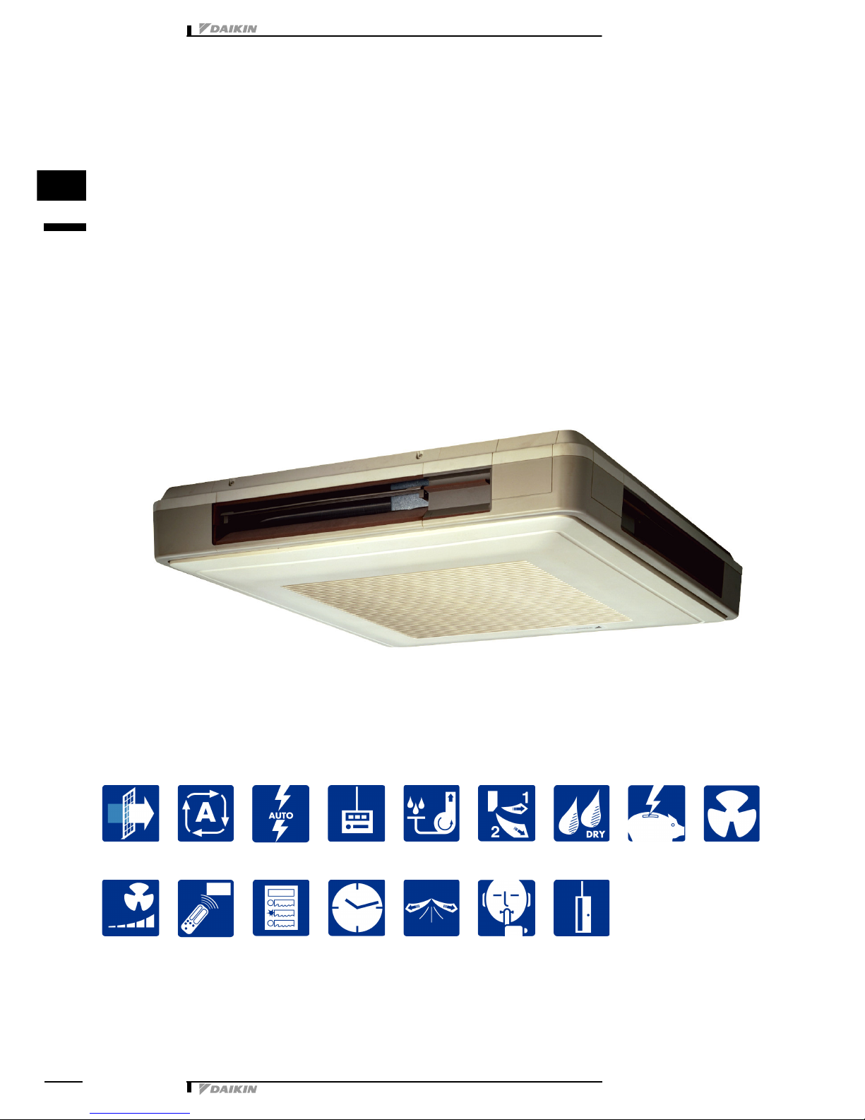
FUQ71∼125B
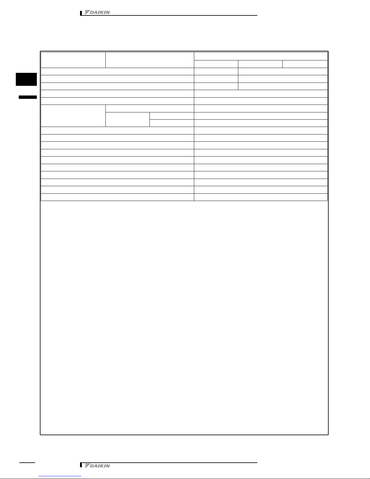
A1P Printed circuit board
C1R Capacitor (M1F)
HAP Light emitting diode (service monitor green)
KAR Magnetic relay (M1S)
KPR Magnetic relay ((M1P)
M1F Motor (indoor fan)
M1P Motor (drain pump)
M1S Motor (swing flap)
Q1M Thermo switch (M1F embedded)
R1T Thermistor (air)
R2T Thermistor (coil)
S1L Float switch (M1A)
S1Q Limit switch (swing flap)
SS1 Selector switch (emergency)
T1R Transformer (220-240V/22V)
V1TR Phase control circuit
X1M Terminal strip
X2M Terminal strip
?Signal receiver circuit
.Signal transmission circuit
Wired remote control
R1T Thermistor (air)
SS1 Selector switch (main/sub)
Receiver / display unit (attached to infrared remote controller)
A2P Printed circuit board
A3P Printed circuit board
BS1 Push button (on/off)
H1P Light emitting diode (service monitor red)
H2P Light emitting diode (service monitor green)
H3P Light emitting diode (service monitor red)
H4P Light emitting diode (service monitor orange)
SS1 Selector switch (main/sub)
SS2 Selector switch (wireless address set)
Connector for optional parts
X35A Connector (group control adapter)
X60A
X61A Connector (interface adapter for sky air series)
To outdoor
unit
Note) 4
Wired remote
control
Control box
In case of simultaneous
operation system.
To outdoor unit
Notes
1. D: Terminal F: Connector
b: Protective earth (screw)
2. : Field wiring
3. In case using central remote control, connect it to the unit in
accordance with the attached instruction manual.
4. X24A is connected when the infrared remote control kit is
being used.
5. Remote control model varies according to the combination
system, confirm technical materials and catalogs, etc. before
connecting.
6. Symbols show as follows Red:red, Blk:black, Ylw:yellow,
Org:orange, Gry:gray, Prp:purple, Blu:blue
7. Confirm the method of setting the selector switch (SS1, SS2)
by installation manual and engeneering materials, etc.
Receiver / display unit
Note) 4
Indoor unit
(master)
Indoor unit
(slave)
Infrared remote
control
Norm. Emerg.


 null")