manuals.online logo
Brands
  1. Home
  2. •
  3. Brands
  4. •
  5. Daikin
  6. •
  7. Chiller
  8. •
  9. Daikin EWLQ Series Operating and maintenance manual

Daikin EWLQ Series Operating and maintenance manual

Installation,
maintenance
& operation
manual
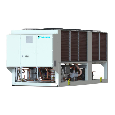
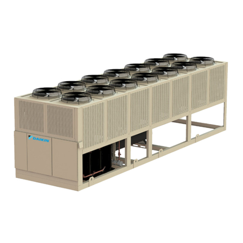
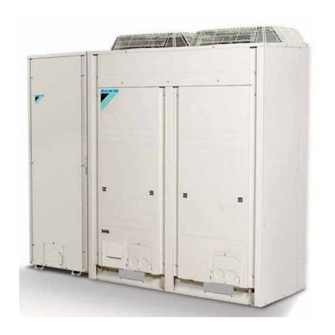
EWWQ090G EWWQ720L Water-cooled scroll chillers
EWLQ090G EWLQ720L Condenserless
EWHQ100G EWHQ400G Heat pump scroll chillers
Refrigerant: R410A
D–EIMWC01206-15EN
REV 00
Date -
Supersedes -
EWLQ-G/L
Condenserless water
cooled chillers
D–EIMWC01206-15EN - 2/20
Thankyouforpurchasingthischiller
Thismanualisanimportantsupportingdocumentforqualifiedpersonnelbutitisnotintendedtoreplacesuchpersonnel.
READTHISMANUALCAREFULLYBEFOREINSTALLINGAND
STARTINGUPTHEUNIT.
IMPROPERINSTALLATIONCOULDRESULTINELECTRICSHOCK,
SHORT-CIRCUIT,COOLANTLEAKS,FIREOROTHERDAMAGETO
THEEQUIPMENTORINJURETOPEOPLE.
THEUNITMUSTBEINSTALLEDBYAPROFESSIONAL
OPERATOR/TECHNICIAN.
UNITSTARTUPHASTOBEPERFORMEDBYAUTHORIZEDAND
TRAINEDPROFESSIONAL.
ALLACTIVITIESHAVETOBEPERFORMEDACCORDINGTO
LOCALLAWSANDREGULATIONS.
UNITINSTALLATIONANDSTARTUPISABOSOLUTELY
FORBIDDENIFALLINSTRUCTIONCONTAINEDINTHISMANUAL
ARENOTCLEAR.
IFCASEOFDOUBTCONTACTTHEMANUFACTURER
REPRESENTATIVEFORADVICEANDINFORMATION.
Contents
The unit purchases is a Water Chiller and/or a Heat
Pump, that is a machine designed to cool/heat the
water (or a water-glycol mixture) within certain limits
which will be listed below. The unit operates based on
the compression, condensation and evaporation of the
coolant gas, according to the Carnot cycle, and is
composed mainly of the following parts depending on
the Mode of Operation.
Cooling or Conditioning Mode:
- One or more scroll compressors that increase the
pressure of the refrigerant gas from evaporation to
condensation pressure.
- A condenser where the refrigerant gas under high
pressure condenses transferring the heat to the
water.
- Expansion valve allowing to reduced the pressure
of condensed liquid refrigerant from condensation
pressure to evaporation pressure.
- Evaporator, where the low pressure liquid
refrigerant evaporates chilling the water
Heating Mode or Heat Pump:
- One or more scroll compressors that increase the
pressure of the refrigerant gas from evaporation to
condensation pressure.
- A 4-way valve which enables the inversion of the
refrigeration cycle.
- A heat exchanger in which the refrigerant
condenses heating the water.
- Expansion valve allowing to reduced the pressure
of condensed liquid from condensation pressure to
evaporation pressure.
- A heat exchanger where the low pressure
refrigerant evaporate removing the heat from the
water.
- The operation of the heat exchangers can be
inverted using the 4-way valve, with which the use
of the heating/cooling unit can be seasonally
inverted.
General Information
All the units are delivered, together withwiring
diagrams, certifieddrawings,nameplateandDoC
(DeclarationofConformity).Thesedocumentslistallthe
technicaldataoftheunitacquiredandCONSTITUTEAN
INTEGRALANDESSENTIALPARTOFTHISMANUAL.
In case of any discrepancy between this manual and
the equipment’s documents please refer to on board
documents. In case of any doubt contact the
manufacturer representative.
The purpose of this manual is to allow the installer and
the qualified operator to ensure proper, commissioning,
operation and maintenance, without any risk to people,
animals or things.
Receiving the unit
The unit must be inspected for any possible damage
immediately upon reaching final place of installation. All
components described in the delivery note must be
inspected and checked.
Should there be evidence of damage, do not remove
the damaged components and immediately report the
extent and type of damage both to the transportation
company, asking them to inspect it, and the
manufacturer's representative, sending if possible
photos which may be useful in identifying the
responsibilities.
Damage must not be repaired before the inspection of
the transportation company representative and the
manufacturer's representative.
Before installing the unit, check that the model and
power supply voltage shown on the nameplate are
correct. Responsibility for any damage after acceptance
cannot be attributed to the manufacturer.
Storage
The unit must be protected from dust, rain, constant
exposure to the sun and possible corrosive agent when
being stored outside before installation.
Even though it is covered by a heat-shrinking plastic
sheet, it is not intended for long-term storage and must
be removed as soon as the unit is unloaded. It must in
fact be protected by tarpaulins and the like which are
more suitable for the long term.
Environmental conditions must be within the following
limits:
Minimum ambient temperature: -20°C
Maximum ambient temperature: +42°C
Maximum relative humidity: 95% without condensation.
If the unit is stored at a temperature under the minimum
ambient temperature, the components could be
damaged, while at a temperature above the maximum
ambient temperature, the safety valves could open and
discharge the refrigerant into the atmosphere.
Lastly, storage in places with condensation of humidity
can damage the electric components.
D-EIMWC01206-15EN - 3/20
Operation
Operation out of the mentioned limits may damage the
unit.
In case of doubts contact manufacturer representative.
Figure 1 - Identification of the labels applied to the electric panel (Standard*)
Single circuit unit
Double circuit unit
Identification of the labels
1 –Manufacturer’s logo
5–Hazardous voltage warning
2–Type of coolant in the circuit/s
6–Non flammable gas symbol
3 –Electrical hazard symbol
7–Identification data of the unit
4–Tighten electrical cables warning
8- Instructions for handling / lifting
*With the exception of the unit's name plate, which is always in the same position, the other plates may be in different
positions depending on the model and options included in the unit.
D-EIMWC01206-15EN - 4/20
Figure 2 - Operating Limits:
Water Temperature exiting the Evaporator (°C)
A –Operation with Water
B -Operation with Glycol + Water Solution
C –Heat pump unit operating limit
Safety
The unit must be firmly secured to the soil.
It is essential to observe the following instructions:
It is forbidden to access the electrical components
without having opened the main switch and
switched off the power supply.
It is forbidden to access the electrical components
without using an insulating platform. Do not access
the electrical components if water and/or moisture
are present.
The sharp edges can cause injuries. Avoid direct
contact and use adequate protection device
Do not insert solid object in the water pipes.
A mechanical filter must be installed on the water
pipe connected to the heat exchanger inlet.
The unit is supplied with high pressure switches
and/or safety valves, that are installed both on the
high-pressure and on the low-pressure sides of the
refrigerant circuit: be careful.
It is absolutely forbidden to remove the protections
of moving parts.
In case of a sudden stop. follow the instructions listed in
the Control Panel Instruction Manual which is part of
the on-board documentation.
It is strongly recommended that the installation and
maintenance operations not be performed along but
with other people.
In case of accidental injury or unease, it is necessary to:
keep calm
Press the alarm button, if present at the installation
site, or open the main switch
move the injured person in a warm place far from
the unit and in rest position
contact immediately emergency rescue personnel of
the building or the Health Emergency Service
wait without leaving the injured person alone until
the rescue operators come
Give all necessary information to the rescue
operators.
Positioning and assembly
The unit must be installed on a sturdy and perfectly
level foundation. For the earthing, a resistant base is
cement must be created with a width greater than that
of the unit. This base must be able to support its
weight.
Anti-vibration supports must be installed between the
frame of the unit and the cement base of the steel
beams; for their installation follow the dimensional
drawing provided with the unit.
The frame of theunit must be perfectly levelled during
installation, if necessary using shims to be inserted
under the anti-vibrators.
Before the first start-up, it is mandatory that the
installation be verified as being level and horizontal
using a laser level or another suitable instrument.
The error in the levelness and the horizontal position
must not be greater than 5 mm per unit up to 7 metres
and 10mm per unit over 7 metres.
If the unit is installed in places that are easily accessible
to people and animals, we recommend that protection
grates be assemble all around to prevent free access.
To guarantee the best performance in the place of
installation, the following precautions and instructions
must be respected:
- Make sure to provide a strong and solid foundation to
reduce noise and vibrations.
- Avoid installing the unit in areas that could be
dangerous during maintenance operations, such as
platforms without parapets, railings or areas not
complying with the requirements to leave a clearance
space all the way around it.
Respect the minimum access distances around the unit:
- 1500 mm in front of the electric panel;
- 1000 mm on all the other sides.
For further solutions, please consult manufacturer
representative.
Water temperature entering the Condenser (°C)
D-EIMWC01206-15EN - 5/20
Noise
The noise generated by the unit is mainly due to the
rotation of compressors.
The noise level for each model size is listed in sales
documentation.
If the unit is correctly installed, operated and maintained
the noise emission level do not require any special
protection device to operate continuously close to the
unit without any risk.
In case of installation with special noise requirements it
could be necessary to install additional sound
attenuation devices.
Handling and lifting
The unit must be lifted with the utmost care and
attention, following the lifting instructions shows on the
label applied to the electric panel. Lift the unit very
slowly, keeping it perfectly level.
Avoid bumping and/or shaking the unit during the
handling and loading/unloading operations from the
transportation vehicle, push or pull the unit only using
the base frame. Secure the unit inside the truck to
prevent it from moving and causing damages. Do not
allow any part of the unit to fall during
loading/unloading.
All units have lifting points marked in yellow. Only these
points may be used for lifting the unit, as shown in the
following figure. The handling and lifting with a fork lift is
the only alternative method.
Both the lifting ropes and the spacing bars must
be strong enough to support the unit safely. Check
the weight of the unit on its name plate, because
the weight of the units varies depending on the
accessories requested.
Figure 3 - Handling of the single circuit unit
Alternative handling method
D-EIMWC01206-15EN - 6/20
Figure 4 - Handling of the double circuit unit
Alternative handling method
1–Remove before installation
2- Use lifting hooks with closing device exclusively.
The hooks must be safely fastened before performing the handling
3–Fork lift
D-EIMWC01206-15EN - 7/20
Sound protection
When sound levels require special control, great care
must be exercised to isolate the unit from its base by
appropriately applying anti-vibrating elements. Flexible
joints must be installed on the water connections, as
well.
Hydraulic circuit for connection to the unit
The pipes must be designed with the lowest number of
elbows and the lowest number of vertical changes of
direction. In this way, installation costs are reduced
considerably and system performance is improved.
The water system must have:
1. Anti-vibrating pipes which reduce the transmission
of vibrations to the structures.
2. Isolating valves to isolate the unit from the water
system of the installation during service operations.
3. Manual or automatic air venting device at the
system’s highest point.; drain device at the system’s
lowest point.
4. Neither the evaporator nor the heat recovery device
must be positioned at the system’s highest point.
5. A suitable device that can maintain the water
system under pressure.
6. Water temperature and pressure indicators to assist
the operator during service and maintenance.
7. A water filter or a device that can remove particles
from the liquid and is mandatory at the entry of the
evaporator.
The filter can be installed at the entrance of the
pump when it is placed on the input pipe of the
water of the evaporator, only if the cleanliness of the
water installation between the pump and the
evaporator is guaranteed. Any slag in the
evaporator causes the warranty of the unit to be
forfeited.
8. If the unit is being replaced, empty and clean the
entire water system before installing a new one and
prior to starting it conduct adequate tests and
chemical treatments of the water.
9. If glycol is added to the water system to provide anti-
freeze protection, the performance of the unit will
decrease. All unit-protection systems, such as anti-
freeze, and low-pressure protection will need to be
readjusted.
10. Before insulating water piping, check that there are
no leaks.
11.Check that the pressure of the water does not
exceed the design pressure of the water side heat
exchangers and install a safety valve on the pipe of
the water.
12. Install a suitable expansion.
CAUTION:
To avoid damages, install a filter that can be
inspected on the water pipes at the entry to the
heat exchangers.
Insulation of the pipes
The complete water circuit, including all the pipes, must
be insulated to avoid condensate from forming and
reducing the cooling capacity.
Protect the water pipes from freezing during the winter
(using for example a glycol solution or a heating cable).
Installing the flow switch
To guarantee sufficient water flow to the entire
evaporator, it is mandatory that a flow switch be
installed on the water circuit which can be positioned on
the incoming or outgoing water pipes. The purpose of
the flow switch is to stop the unit in the event of
interrupted water flow, thus protecting the evaporator
from freezing.
The manufacturer may offer a flow switch specially
selected for this purpose.
This paddle-type flow switch is suitable for heavy-duty
applications.
It has a clean contact that is electrically connected to
the terminals shown in the wiring diagram, and must be
calibrated so that it intervenes when the flow of the
water of the evaporator drops below 80% of the nominal
flow and in any case within the limits listed in the
following table.
Preparation, check and connection of the water
circuit
The units have a water input and output for the
connection of the chiller to water circuit of the system.
This circuit must be connected to the unit by an
authorised technician and must comply with all the
current national and European regulations on the
subject.
NOTE - The components listed below are not included
with the unit, but are supplied upon request, also if
their installation is compulsory.
If dirt penetrates the water circuit, there could
be problems. Therefore always remember the
following when connecting the water circuit:
1.
Only use pipes that are clean inside.
2. Keep the end of the pipe facing downward
when removing the burrs.
3. Cover the end of the pipe when inserting it
through a wall to avoid dust and dirt getting
in.
4. Clean the pipes of the system located
between the filter and the unit, with running
water, before connecting it to the system.
1 2 3 4 5 6 7
1 Evaporator water entry
2 Flow Switch
3 Water entry sensor
4 Water entry pipe with flow switch and
temperature sensor of the incoming water
5 Joint
6 Counter-pipe
7 In situ water pipe circuit
8 Filter
9 Filter and cup
The water in the system must be particularly clean and
all traces of oil and rust must be removed. Install a
mechanical filter at the entry of every heat exchanger.
The failure to install a mechanical filter allows solid
particles and/or welding burrs to get inside the
exchanger. We recommend installing a filter with a
filtering mesh with holes not larger than 1.1mm in
diameter.
The manufacturer cannot be maintained responsible for
any damage to the exchangers if the mechanical filters
are not installed.
Water treatment
Before putting the unit into operation, clean the water
circuit. Dirt, scales, debris and other material can
accumulate inside the heat exchanger and reduce both
its heat exchanging capacity and the flow of the water.
An adequate treatment of the water can reduce the risk
of corrosion, erosion, scale formation, etc. The must
suitable treatment must be selected depending on the
place of installation, considering the water system and
the characteristics of the water.
The manufacturer is not responsible for any damages
or malfunctions of the equipment
The quality of the water must comply with the
specifications listed in the following table.
Circulating
water
Water
supply
Possible
problems
Elements to be checked
pH at 25°C
6.8~8.0
6.8~8.0
Corrosion
+ limescale
Electrical
conductivity
[mS/m] at 25°C
<40
<30
Corrosion
+ limescale
Chlorine ion
[mg Cl˜/l]
<50
<50
Corrosion
Sulfate ion
[mg SO4²˜/l]
<50
<50
Corrosion
Alkalinity M
(pH4.8)
[mg CaCO3/l]
<50
<50
Limescale
Total hardness
[mg CaCO3/l]
<70
<70
Limescale
Hardness of the
Calcium
[mg CaCO3/l]
<50
<50
Limescale
Silicon ion
[mg SiO2/l]
<30
<30
Limescale
Elements of reference
Iron
[mg Fe/l]
<1.0
<0.3
Corrosion
+
Limescale
Copper
[mg Cu/l]
<1.0
<0.1
Corrosion
Sulphide ion
[mg S²˜/l]
Non
detectabl
e
Non
detectabl
e
Corrosion
Ammonium ion
[mg NH4+/l]
<1.0
<0.1
Corrosion
Remaining
Chloride
[mg Cl/l]
<0.3
<0.3
Corrosion
Free Carbide
[mg CO2/l]
<4.0
<4.0
Corrosion
Index of stability
-
-
Corrosion
+ limescale
The pressure of the water must exceed the
maximum operating pressure anticipated for the unit.
NOTE - Plan adequate protections in the water circuit to
make sure that the pressure of the water never exceeds
the maximum limit allowed.
Flow and volume of the water
EWWQ Model
Minimum water
flow
l/s
Maximum
water flow
l/s
EWWQ090G
2.70
5.63
EWWQ100G
3.04
6.34
EWWQ120G
3.42
7.13
EWWQ130G
3.91
8.14
EWWQ150G
4.31
8.98
EWWQ170G
4.94
10.30
EWWQ190G
5.57
11.60
EWWQ210G
6.34
13.21
EWWQ240G
7.07
14.73
EWWQ300G
9.04
18.83
EWWQ360G
10.64
22.18
8
8
9
D-EIMWC01206-15EN - 9/20
EWWQ180L
5.38
11.21
EWWQ205L
6.17
12.86
EWWQ230L
7.01
14.61
EWWQ260L
7.82
16.30
EWWQ290L
8.70
18.13
EWWQ330L
9.89
20.60
EWWQ380L
11.11
23.14
EWWQ430L
12.35
25.73
EWWQ480L
13.66
28.46
EWWQ540L
15.77
32.86
EWWQ600L
17.56
36.58
EWWQ660L
19.06
39.71
EWWQ720L
20.74
43.21
EWLQ Model
Minimum water
flow
l/s
Maximum
water flow
l/s
EWLQ090G
2.50
5.21
EWLQ100G
2.85
5.94
EWLQ120G
3.19
6.65
EWLQ130G
3.61
7.53
EWLQ150G
4.02
8.38
EWLQ170G
4.61
9.61
EWLQ190G
5.24
10.91
EWLQ210G
5.90
12.30
EWLQ240G
6.61
13.76
EWLQ300G
8.39
17.48
EWLQ360G
10.00
20.83
EWLQ180L
4.97
10.36
EWLQ205L
5.67
11.81
EWLQ230L
6.42
13.38
EWLQ260L
7.13
14.86
EWLQ290L
8.00
16.68
EWLQ330L
9.09
18.94
EWLQ380L
10.37
21.60
EWLQ430L
11.75
24.48
EWLQ480L
13.16
27.43
EWLQ540L
14.69
30.60
EWLQ600L
16.40
34.16
EWLQ660L
17.92
37.33
EWLQ720L
19.43
40.49
EWHQ Model
Minimum water
flow
l/s
Maximum
water flow
l/s
EWHQ100G
3.80
7.91
EWHQ120G
4.19
8.74
EWHQ130G
4.77
9.94
EWHQ150G
5.41
11.26
EWHQ160G
5.98
12.45
EWHQ190G
6.83
14.24
EWHQ210G
7.80
16.25
EWHQ240G
8.95
18.64
EWHQ270G
9.94
20.71
EWHQ340G
12.51
26.06
EWHQ400G
14.82
30.88
To ensure the correct operation of the unit, the flow of
water in the evaporator must fall within the operating
sphere specified in the preceding table and there must
be a minimum volume of water in the system.
The distribution circuits of the cold water should have a
minimum content of water to avoid an excessive
number of start-up and shut-downs of the compressor.
In fact, every time the compressor goes into operation,
an excessive amount of oil from the compressor starts
circulating in the refrigerant circuit and at the same time
there is an increase of the temperature of the
compressor stator, generated by the inrush current of
the start-up. Therefore to avoid damages to the
compressors, the application of a device has been
planned to limit frequent shut-downs and start-ups: in
one hour, there will only be 6 start-ups of the
compressor.
The system where the unit is installed must therefore
ensure that the overall content of water allows the unit t
operate continuously and therefore greater
environmental comfort. The minimum water content per
unit must be calculated with a certain approximation
using the following formula:
For units with 2 compressors:
M(litres) = (12.153 x DT (°C) –22.168) x P(kW)
For units with 4 compressors:
M(litres) = (0.32 x DT (°C) +1,36) x P(kW)
Where:
M = minimum content of water per unit expressed in
litres
P = refrigerating capacity of the unit express in kW
ΔT = difference in temperature of the incoming and
outgoing water, expressed in °C.
This formula is valid with the standard parameters of
the microprocessor. To determine most accurately the
quantity of water, we recommend contacting the
designer of the system.
Anti-freeze protection for evaporators and recovery
exchangers
When the entire system of the cooling or heating
installation is being designed, two or more of the
following anti-freeze protection methods should be
considered at the same time:
1. Continuous circulation of the flow of water inside the
exchangers
2. Additional heat insulation and heating of exposed
piping
3. Emptying and cleaning of the heat exchanger during
the winter and its maintenance with anti-oxidant
atmosphere (nitrogen).
As an alternative, it is possible to add an appropriate
amount of glycol (antifreeze) to the water circuit.
The installer and/or the local personnel assigned to
maintenance must make sure that anti-freeze protection
methods are in use and ensure that the appropriate
maintenance operations of the antifreeze protection
devices are always carried out. Failing to follow the
instructions above could result in unit damage. Damage
caused by freezing is not covered by the warranty.
Electrical system General Specifications
The units must be connected to a TN power supply
system.
If the units must be connected to a different type of
power system, for example the IT system, please
contact the factory.
All the electrical connections to the unit must
be carried out in compliance with national laws
and European directives and regulations in
force.
All installation, management and maintenance activities
must be carried out by qualified personnel.
D-EIMWC01206-15EN - 10/20
Refer to the specific wiring diagram for the unit
purchased. Should the wiring diagram not be on the unit
or should it have been lost, please contact the
manufacturer representative who will send you a copy.
In case of discrepancy between the wiring diagram and
the visual check of the electric wires of the command
and control panel, contact the manufacturer
representative.
Use only copper conductors to avoid overheating or
corrosion in the connection points, with resulting risk of
damage to the unit.
To avoid interference, all the command and control
cables must be connected separately from the power
ones, using several raceways for this purpose.
Before performing service operations on the unit, open
the general disconnection switch located on the main
power supply.
CAUTION: If the unit is off but the disconnection switch
is in the closed position, the circuits not being used will
still be active.
Never open the terminal board of the compressors
without having disconnected the main switch of the
machine.
Simultaneous mono and three-phase loads and
imbalance between the phases can cause leakage
towards earth up to 150mA during the normal operation
of the unit.
The protections for the power supply system must be
designed based on the values mentioned above.
Wiring at the installation location
The operations of wiring at the installation
location and possibly other components must be
performed by an authorized technician and must
comply with the current national and European laws on
the subject.
The on-site wiring must be done in conformity with the
wiring diagram supplied with the machine and the
instructions listed below.
Make sure to use a dedicated electric circuit. Never use
a power supply shared with other equipment.
NOTE - Verify on the wiring diagram all the operations
listed below in order to better understand how the
equipment operates.
Components table:
F1, 2 Main fuses of the equipment
L1, 2, 3 Main power supply terminals
PE Main earth terminal
FS Switch
Q10 Main insulator switch
--- On-site wiring
Electric circuit and wiring requirements
1. The power supply to the unit must be prepared
so that it can be turned on and off
independently from that of other components
of the system or other appliances in general.
2. Plan an electrical circuit for the connection of
the unit. This circuit must be protected with the
necessary safety devices, that is a main
switch, an SB fuse on each phase and a
leakage towards earth detector. The
recommended fuses are listed in the wiring
diagram provided with the unit.
Turn off the switch of the main insulator before
performing any connection (turn off the switch, remove
or disable the fuses).
Connection of the power supply
ofthe unit
Using the suitable wire, connect the power circuit to the
terminals L1, L2 and L3 of the electric panel.
CAUTION: Never twist, pull or apply weight to the
terminals of the main switch. The wires of the power
supply line must be supported by adequate systems.
The wires connected to the switch must respect the
elevated insulation distance and the distance of surface
insulation between the active conductors and the mass,
in accordance with IEC 61439-1, Table 1 and 2 and
local national laws.The wires connected to the main
switch must be tightening using a wrench torque and
complying with the unified tightening values relative to
the quality of the screws of the washers and the nuts
used.
2 Connect the earthing conductor (yellow/green) to the
PE earthing terminal.
Interconnecting wires
Usually the appliance does not work without
flow, thanks to the flow meter installed standard,
however, to be doubly safe, it is compulsory that a
status contact of the water pump be installed in series
with the contact of the flow meter/s in order to prevent
the unit from operating if the pump has not started.
If the unit starts operating without flow, very serious
damage occurs (freezing of the evaporator).
Clean contacts
The controller has some clean contacts to indicate
the status of the unit. These contacts can be wired as
shown in the wiring diagram. The maximum current
allowed is 2 A.
Remote inputs
In addition to the clean contacts, it is also possible
to install remote inputs. For installation check the
wiring diagram.
Before start-up
The unit must be started for the first time
ONLY by DAIKIN authorised personnel.
The unit must absolutely not be started, even for a very
short period of time, without having checked it in minute
detail filling out the following list at the same time.
Checks to be performed before starting
the unit
1
Check for exterior damage
2
Open all the closing valves
D-EIMWC01206-15EN - 11/20
3
Make sure that all the parts of the unit are
pressurized with refrigerant(evaporator,
condenser, compressors) before
connecting it to the hydraulic circuit.
4
Install the main fuses, earthing leakage
detector and main switch. Fuses
recommended: aM compliant with the IEC
269-2 standard.
For the dimensions, check the wiring
diagram.
5
Connect the main voltage and check that it
falls within the limits allowed of ±10%
compared to the classification listed on the
name plate.
The main power supply must be
arranged so that it can be turned on or off
independently from that of other parts of
the system or other appliances in general.
Check the wiring diagram, terminals L1, L2
and L3.
6
Install the water filter kit/s (also when not
supplied) at the entrance of the
exchangers.
7
Supply water to the exchangers and make
sure that the flow falls within the limits
shown in the table in the "Load, flow and
quality of the water" paragraph.
8
The pipes must be completely flushed
out. See the chapter "Preparation, check
and connection of the water circuit".
9
Connect the contact/s of the pump in
series with the contact of the flow meter/s
so that the unit can only be activated when
the water pumps are operating and the
flow of water is sufficient.
10
Check the level of the oil in the
compressors.
11
Check that all the water sensors are
fastened correctly in the heat exchanger
(see also sticker applied on the heat
exchanger).
NOTE - Before starting the unit, read the operating
manual provided with it. It will help you to better
understand the operation of the equipment and the
relative electronic controller, and close the doors of the
electric panel.
Open the isolation and/or shut off valves
Before start-up, make sure that all the isolation and/or
switch off valves are completely open.
Responsibility of the user
It is essential that the user is appropriately trained and
becomes familiar with the system before operating the
unit. In addition to reading this manual, the user must
study the microprocessor operating manual and the
wiring diagram in order to understand start-up
sequence, operation, shutdown sequence and
operation of all the safety devices.
The user must keep a log (system booklet) of the
operating data of the unit installed and of all the periodic
maintenance and service activities.
If the operator notes abnormal or unusual operating
conditions, he is advised to consult the authorized
technical service of the manufacturer.
Periodic maintenance
The periodic maintenance activities (minimum), are
listed in the specific table of this manual
Version with remote condenser
Connection of the refrigerant circuit
This version is charged at the factory with Nitrogen.
The units are equipped for the refrigerant circuit with an
output pipe (delivery side) and an input pipe (liquid side)
which must both be connected to a remote condenser.
This circuit must be operationally created by an
authorized technician and must comply with all the
national and European laws, directives and regulations.
Precautions when handling the pipes
If air or dirt penetrate the refrigerant circuit,
there could be problems. Therefore always remember
the following when connecting the circuit:
1. Only use clean pipes.
2. Ensure the absolute cleanliness of the pipes
after the operations have been performed.
3. Keep the end of the pipe facing downward
when removing the processing burrs. Cover
the end of the pipe when inserting it through a
wall to avoid dust and dirt getting in.
To perform the connection, the delivery and liquid pipes
must be soldered directly to pipes of the remote
condenser. In order to use the correct pipe diameter,
please refer to the dimensions drawing supplied with
the unit.
Make sure that the pipes are discharged of
Nitrogen during the soldering / welding, to protect them
from soot.
Seal and vacuum test
The moto-evaporating units have already been checked
at the factory guaranteeing that there are no leaks.
Once the pipes have been connected, a leak test must
be performed once again.
The air in the refrigerant circuit must be evacuated at a
value of 4 mbar absolute, using the vacuum pumps.
Do not clean out the air with the refrigerants. Use a
vacuum pump to eliminate the air from the system.
Refrigerant charge
Perform a full inspection before user, as explained in
the paragraph Beforestart-up.
Carefully perform the procedure required and the
methods explain the paragraph Before start-up, but do
not start the unit.
D-EIMWC01206-15EN - 12/20
Pre-charging the refrigerant when the unit is not
running
Pre-charge the equipment with the quantity of
refrigerant anticipated using the Flare SAE 1/4" stop
valve on the filter of the liquid.
CAUTION: To avoid damage to the compressor, do not
start it to speed up the pre-charge.
Once the pre-charge has been completed, ask your
manufacturer representative to perform the first start-
up.
Adjustment of the refrigerant charge with the unit
running.
CAUTION: Only for the personnel authorized to
perform the first start up.
To adjust the charge of the refrigerant, use the 1/4"
Flare SAW valve on the pipe of the liquid and make
sure to load the refrigerant in its liquid state.
To adjust the charge of the refrigerant, the compressor
must be operating at full load (100%).
Verify:
The overheating which must be between 3 and 8
°Kelvin
The sub-cooling which must be between 4 and 8
°Kelvin
The inspection glass of the oil. The level must be within
the glass.
The see-through window of the pipe of the liquid which
must be full and not show humidity in the refrigerant. If
the see-through window of the pipe of the liquid is not
full, gradually add refrigerant and wait for the operation
of the unit to stabilize.
Add refrigerant until all the verification parameters are
within the limits.
The unit must have time to stabilize, which means that
the charge must be done gradually and steadily.
Note the overheating and sub-cooling values for future
reference.
CAUTION: Note on the specific label the total charge of
refrigerant put into the circuit.
NOTE - Pay attention to a possible contamination of the
remote condenser to avoid blocking the system.
The manufacturer cannot check the contamination of
the "outside" condenser of the installer. The unit has a
precise level of contamination.
In accordance with the Directive 2006/42/EC
APPENDIX II B the units, named EWLQ090 →
EWLQ720 are defined as “quasi-machines”.
The aforementioned products cannot be put into
operation until the final machine in which it must be
incorporate meet the legal standards.
Service and limited warranty
All the units are tested at the factory and guaranteed for
a specific period of time.
These units have been developed and constructed
according to high quality standards ensuring years of
failure-free operation. However, it is important to ensure
proper and periodical maintenance in accordance with
all the procedures listed in this manual and with good
practice of machines maintenance.
We strongly recommend stipulating a maintenance
contract with a service authorized by the manufacturer.
The experience and skill of the personnel, in fact, can
ensure an efficient operation without problems over
time.
The unit must be covered by a suitable maintenance
program from the time it is installed and not just from
the start-up date.
Keep in mind that operating the unit in an inappropriate
manner, beyond its operating limits or not performing
proper maintenance according to this manual will void
the warranty.
Observe the following points in particular, in order to
conform to warranty limits:
1. The unit cannot function beyond the specified
limits
2. The electrical power supply must be within the
voltage limits and without voltage harmonics or
sudden changes.
3. The three-phase power supply voltage must not
have an imbalance between the phases greater
than 2% in accordance with EN 60204-1:2006
(Chapter 4-Par.4.3.2).
4. In case of electrical problems, the unit must
remain
5. off until the problem has been solved.
6. Do not disable or cancel the safety devices,
7. whether mechanical, electrical or electronic.
8. The water used for filling the water circuit must
be clean and suitably treated. A mechanical filter
must be installed at the point closest to the
evaporator inlet.
9. Unless specifically agreed at the time of the
order, the flow of water of the evaporator must
never exceed 120% or be below 80% of the
nominal capacity and in any case within the
limits provided in this manual.
Periodic obligatory checks and starting up ofthe
Groups (units)
These Groups (units) are included in category III of the
classification established by the European Directive
PED 97/23/EC.
For Groups belonging to this category,some national
laws require a periodic check by an authorized
organization. Please verify and contact these
organizations to also request authorization to start it up.
D-EIMWC01206-15EN - 13/20
Table 1 - Periodic maintenance programme
List of Activities
Weekly
Monthly
(Note 1)
Annually /
Seasonally
(Note 2)
General:
Reading of operating data (Note 3)
X
Visual inspection of machine for any damage and/or loosening
X
Verification of thermal insulation integrity
X
Clean and paint where necessary (Note 4)
X
Analysis of water
X
Check of flow switch operation
X
Electrical:
Verification of start-up sequence
X
Verify the wear of the contactors –If necessary replace them
X
Verify the that all the electrical terminals are tight –Tighten if necessary
X
Clean inside the electrical board (Note 4)
X
Clean the aeration filters of the electrical board (Note 4)
X
Visual inspection of components for any signs of overheating
X
Verify operation of compressor and electrical resistance
X
Measure with the Megger the insulation of the compressor motor
X
Refrigerant Circuit:
Check for any refrigerant leakage
X
Verify using the liquid see-through window, the flow of refrigerant - See-
through window full
X
Check on filter dryer pressure drop (if present)
X
Perform the analysis of the vibrations of the compressor
X
Verify safety valve (Note 5)
X
Heat exchangers:
Verify the cleanliness of the heat exchangers (Note 6)
X
Notes:
1) The monthly activities include all the weekly ones
2) The annual activities (or start of season) include all the weekly and monthly activities
3) The operating values of the machine should be noted daily for a high level of control.
4) If the unit is installed in an aggressive environment, perform this activity monthly.
The following are considered aggressive environments:
- place with high concentration of industrial exhaust gas in the air;
- Place close to the sea (salt air);
- Place close to a desert where there is a risk of sand storms;
- Other aggressive environments.
5) Safety valve
Check that the cap and seal have not been tampered with.
Check that the safety valve discharge connection has not been accidentally clogged
by extraneous objects, rust or ice.
Check the manufacture date located on the safety valve and replace it in conformity with current national laws.
6) Clean the heat exchangers. Particles and fibres could clog the heat exchanger. An increase in the flow of water or a
drop in heat efficiency indicates that the heat exchangers are clogged.
Discharge of the refrigerant from the safety valves
Avoid discharging refrigerant from the safety valves at
the installation site. If necessary, it is possible to
connect them to discharge pipes, the transversal
section and length of which must comply with the
national laws and the European directives.
Important information regarding the refrigerant
used
This product contains fluorinated greenhouse gases.
Do not disperse the refrigerant gas into the atmosphere.
Refrigerant type: R410A
GWP value: 2087.5
(1)GWP = Global Warming
Potential
The refrigerant quantity necessary for standard
operation is indicated on the unit name plate.
The actual quantity of refrigerant charged in the unit is
listed on a silver plate inside the electrical panel.
Based on the provisions of the national or European
legislations, periodic inspections may be
necessary to identify potential leaks of
D-EIMWC01206-15EN - 14/20
refrigerant. Please contact your local dealer for more
information.
Life of the product
The life of our products is 10 (ten) years.
Disposal
The unit is made of metal, plastic and electronic parts.
All these parts must be disposed of in accordance with
the national and European laws in effect relative to this
substance.
Lead batteries must be collected and sent to specific
refuse collection centres.
Oil must be collected and sent to specific refuse
collection centres.
This manual is a technical aid and does not represent a binding offer. We cannot guarantee explicitly or implicitly the completeness, accuracy or reliability of
its contents. All data and specifications contained herein may be modified without notice. The data communicated at the time of the order shall hold firm.
The manufacturer shall assume no liability whatsoever for any direct or indirect damage, in the widest sense of the term, ensuing from or connected with
the use and/or interpretation of this manual.
We reserve the right to make changes in design and construction at any time without notice. Consequently, the image on the cover is not binding.
D-EIMWC01206-15EN - 15/20
Figure 5 - Wiring for connecting the unit at the place of installation
Legend
Conditioning
Version
Heat Pump
Version
Moto-Evaporating
Version
AI
Analog Inputs
A.R.
ON / OFF remote
AO
Analog Output
CFS
Condenser Flow Switch
CP-
VFD
VFD (Variable Frequency Drive)
condenser pump
VFD 3 Way Valve
VFD 3 Way
Valve
VFD Fans
D.L.
Limit of charge
DI
Digital Inputs
DO
Digital Outputs
DPS
Digital Setpoint
EF
External Fault
EFS
Evaporator Flow Switch
GA
General Alarm
KPC-1
Pump 1
condenser water
KPC-2
Pump 2
condenser water
KPE-1
Pump 1
evaporator water
S.O.
Exclusion of the
set point
1
HP Version only (Cooling-Heating
Remote)
2
VFD # 2 ON-OFF
(Moto-Evaporating Version only)
Tower Fans
ON/OFF
Tower Fans
ON/OFF
Fans
ON/OFF
Figure A - Typical single refrigerant circuit
The input and output of the water of the condenser and the evaporator are approximate. Consult the dimensional drawings of the unit for the exact hydraulic connections.
D-EIMWC01206-15EN - 17/20
Figure B - Typical single refrigerant circuit of the moto-evaporating version
The input and output of the water of the evaporator are approximate. Consult the dimensional drawings of the unit for the exact hydraulic connections.
D-EIMWC01206-15EN - 18/20
Figure C - Typical single refrigerant circuit for Heat Pump
The input and output of the water of the condenser and the evaporator are approximate. Consult the dimensional drawings of the unit for the exact hydraulic connections.
D-EIMWC01206-15EN - 19/20
Legend
1
Compressor
2
Discharge shut off valve
3
Condenser
4
Liquid line isolating valve
5
Drier filter
6
Shut off valve (charge
valve)
7
Liquid and humidity
indicator
8
Electronic expansion valve
9
Evaporator
10
Suction shut off valve
(optional)
11
Low-pressure safety valve
12
High-pressure safety valve
13
Heat recovery
14
Liquid receiver
15
4 Way valve
16
Refrigerant outlet
connection (to the remote
condenser)
17
Refrigerant inlet
connection (from the
remote condenser)
18
Condenser leaving water
connection
19
Condenser entering water
connection
20
Evaporator leaving water
connection
21
Evaporator entering water
connection
22
Heat recovery leaving
water connection
23
Heat recovery entering
water connection
DT
Discharge temperature
control
CP
High pressure transducer
F13
High-pressure switch
ST
Temperature sensor
EP
Low pressure transducer
CLWT
Condenser leaving water
temperature sensor
CEWT
Condenser entering water
temperature sensor
ELWT
Evaporator leaving water
temperature sensor
EEWT
Evaporator entering water
temperature sensor
For more information email [email protected] or visit www.daikinapplied.uk
For all Daikin Applied UK,
Daikin Applied Service &
Spares enquiries call us on:
0345 565 2700
The present publication is drawn up by way of information only and does not constitute an offer binding upon Daikin Europe
N.V. Daikin Europe N.V. has compiled the content of this publication to the best of its knowledge. No express or implied warranty
is given for the completeness, accuracy, reliability or fitness for particular purpose of its content and the products and services
presented therein. Specifications are subject to change without prior notice. Daikin Europe N.V. explicitly rejects any liability for
any direct or indirect damage, in the broadest
sense, arising from or related to the use and/or
interpretation of this publication. All content is
copyrighted by Daikin Europe N.V.
Daikin Europe N.V. participates in the Eurovent Certified Performance programme
for Liquid Chilling Packages and Hydronic Heat Pumps, Fan Coil Units and Variable
Refrigerant Flow systems. Check ongoing validity of certificate:
www.eurovent-certification.com

This manual suits for next models

59

Other Daikin Chiller manuals

Daikin EUWAC8FZW1 User manual

Daikin

Daikin EUWAC8FZW1 User manual

Daikin EWWQ-AJYNN User manual

Daikin

Daikin EWWQ-AJYNN User manual

Daikin FWW Series User manual

Daikin

Daikin FWW Series User manual

Daikin MAGNITUDE WMT Owner's manual

Daikin

Daikin MAGNITUDE WMT Owner's manual

Daikin EWWD170~600G-SS User manual

Daikin

Daikin EWWD170~600G-SS User manual

Daikin SkyAir RZF-A Series User manual

Daikin

Daikin SkyAir RZF-A Series User manual

Daikin WGZ030DW User manual

Daikin

Daikin WGZ030DW User manual

Daikin EWAD120MBYNN1 User manual

Daikin

Daikin EWAD120MBYNN1 User manual

Daikin EWAA004D2V3P-H User manual

Daikin

Daikin EWAA004D2V3P-H User manual

Daikin Clima-Flex CLIC STAND ALONE Series User manual

Daikin

Daikin Clima-Flex CLIC STAND ALONE Series User manual

Daikin EWLQ014KCW1N User manual

Daikin

Daikin EWLQ014KCW1N User manual

Daikin SERHQ020BAW1 User guide

Daikin

Daikin SERHQ020BAW1 User guide

Daikin EWWQ-KC User manual

Daikin

Daikin EWWQ-KC User manual

Daikin LXE10D-A4 Troubleshooting guide

Daikin

Daikin LXE10D-A4 Troubleshooting guide

Daikin EWAQ005ADVP User manual

Daikin

Daikin EWAQ005ADVP User manual

Daikin EWWD VZ Series Operating and maintenance manual

Daikin

Daikin EWWD VZ Series Operating and maintenance manual

Daikin FWW Series User manual

Daikin

Daikin FWW Series User manual

Daikin EWAA011-016DAV3P User manual

Daikin

Daikin EWAA011-016DAV3P User manual

Daikin EWAP400MBYNN User manual

Daikin

Daikin EWAP400MBYNN User manual

Daikin EWAP 800-C18AJYNN User manual

Daikin

Daikin EWAP 800-C18AJYNN User manual

Daikin EWWD320 User manual

Daikin

Daikin EWWD320 User manual

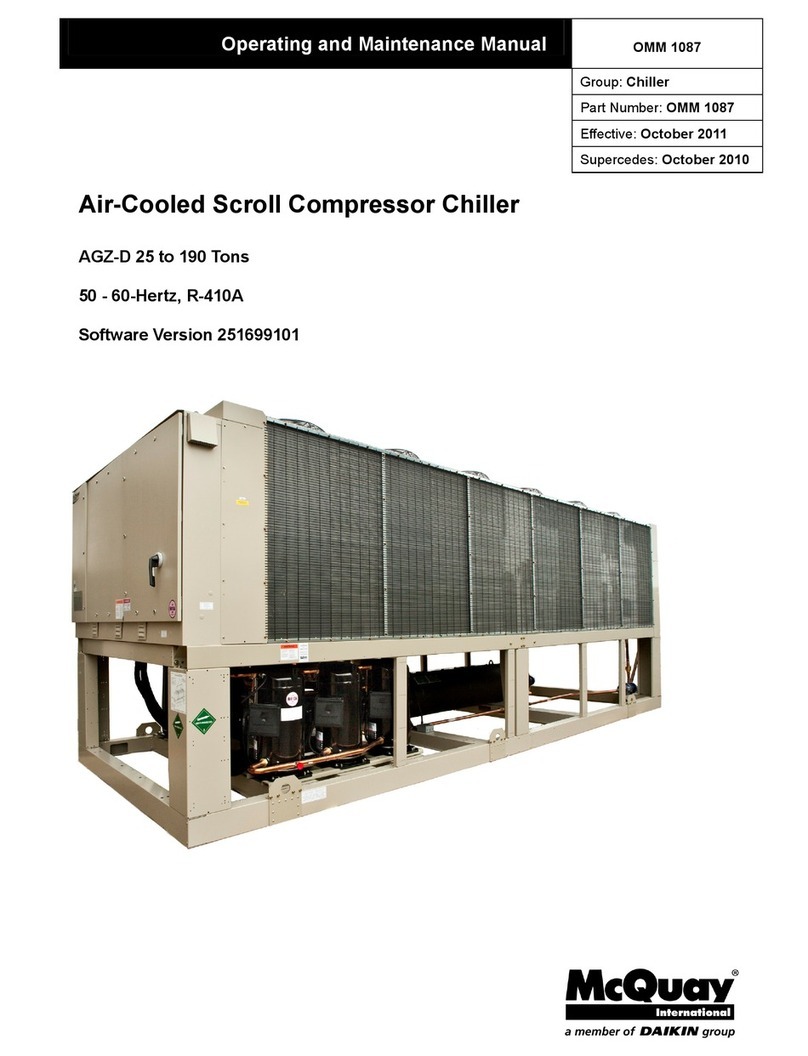
Daikin McQuay AGZ-D Operating instructions

Daikin

Daikin McQuay AGZ-D Operating instructions

Daikin EWWQ-G User manual

Daikin

Daikin EWWQ-G User manual

Daikin FUD20B User manual

Daikin

Daikin FUD20B User manual

Popular Chiller manuals by other brands

SMC Networks HRS100-A?-20-? Operation manual

SMC Networks

SMC Networks HRS100-A?-20-? Operation manual

Lennox EcoLean EAC0091S Installation operating & maintenance manual

Lennox

Lennox EcoLean EAC0091S Installation operating & maintenance manual

York YLHA 50 user manual

York

York YLHA 50 user manual

SMC Networks HRS Series manual

SMC Networks

SMC Networks HRS Series manual

Viessmann Vitoclima 200-C Service instructions for contractors

Viessmann

Viessmann Vitoclima 200-C Service instructions for contractors

CLIMAVENETA i-LIFE2 manual

CLIMAVENETA

CLIMAVENETA i-LIFE2 manual

York YR owner's manual

York

York YR owner's manual

Across International C20 user manual

Across International

Across International C20 user manual

Carrier 30GX080-265 Controls, start-up, operation, service, and troubleshooting

Carrier

Carrier 30GX080-265 Controls, start-up, operation, service, and troubleshooting

Clint CHA Series INSTALLATION, USE AND MANTEINANCE MANUAL

Clint

Clint CHA Series INSTALLATION, USE AND MANTEINANCE MANUAL

Bromic Heating MEDIFRIDGE MEDO374GD instruction manual

Bromic Heating

Bromic Heating MEDIFRIDGE MEDO374GD instruction manual

Kaysun Mini Amazon KMF-180 DTR6 Owners and installation manual

Kaysun

Kaysun Mini Amazon KMF-180 DTR6 Owners and installation manual

Hyco Sapphire SAPUC1 Product instruction manual

Hyco

Hyco Sapphire SAPUC1 Product instruction manual

Lauda MC 250 Operation instructions

Lauda

Lauda MC 250 Operation instructions

Zip HydroChill HC05T128 Installation instructions & user manual

Zip

Zip HydroChill HC05T128 Installation instructions & user manual

TECO TR 10 Resetting guide

TECO

TECO TR 10 Resetting guide

Hoshizaki Lancer P400T V2 Installation, operation & service manual

Hoshizaki

Hoshizaki Lancer P400T V2 Installation, operation & service manual

Zanussi ZANUSSI easyChill BCFW061 Brochure & specs

Zanussi

Zanussi ZANUSSI easyChill BCFW061 Brochure & specs

manuals.online logo
manuals.online logoBrands
  • About & Mission
  • Contact us
  • Privacy Policy
  • Terms and Conditions

Copyright 2025 Manuals.Online. All Rights Reserved.