Daktronics Sportsound Rack SSR-100 User manual

201 Daktronics Drive PO Box 5128 Brookings, SD 57006-5128
Tel: 1-800-DAKTRONICS (1-800-325-8766) Fax: 605697-4746
www.daktronics.com/support
Sportsound®Rack
SSR-100
Operation Manual
DD2746938 Rev 2 – 13 July 2015

DD2746938
P1756
Rev 2 – 13 July 2015
daktronics, inc.
Copyright © 2012-2015
All rights reserved. While every precaution has been taken in the preparation of this manual, the publisher assumes no
responsibility for errors or omissions. No part of this book covered by the copyrights hereon may be reproduced or copied in any
form or by any means – graphic, electronic, or mechanical, including photocopying, taping, or information storage, and retrieval
systems – without written permission of the publisher.
Sportsound®is a registered trademark of Daktronics, Inc. All other trademarks are property of their respective companies.

Table of Contents i
Table of Contents
Section 1: Introduction.......................................................................................................................................... 1
1.1 Resources............................................................................................................................................................... 1
1.2 Daktronics Nomenclature................................................................................................................................... 2
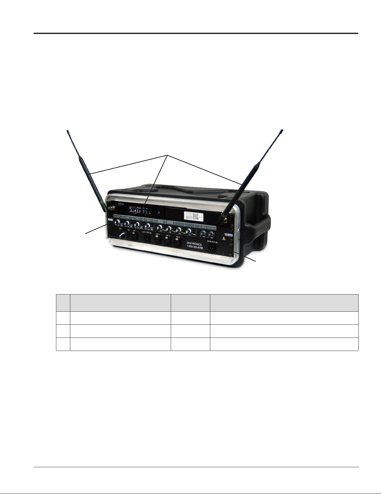
Section 2: SSR-100 Components ......................................................................................................................... 3
2.1 Overview ............................................................................................................................................................... 3
2.2 Standard Equipment............................................................................................................................................ 4
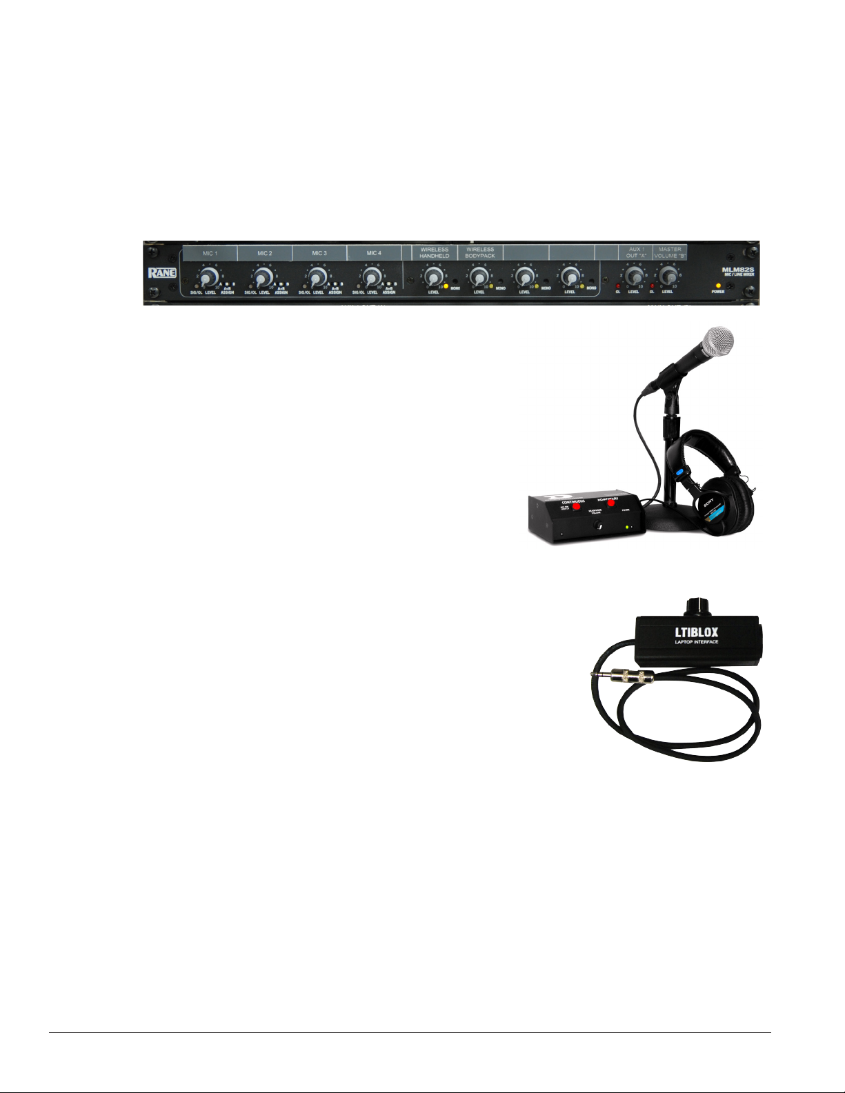
Audio Mixer................................................................................................................................................... 4
Announcer’s Interface .................................................................................................................................. 4
Laptop Interface ............................................................................................................................................ 4
2.3 Optional Equipment ............................................................................................................................................ 4
Wireless Microphone System...................................................................................................................... 4
High Gain Antenna Kit ................................................................................................................................ 5
Single-Muff Headset..................................................................................................................................... 5
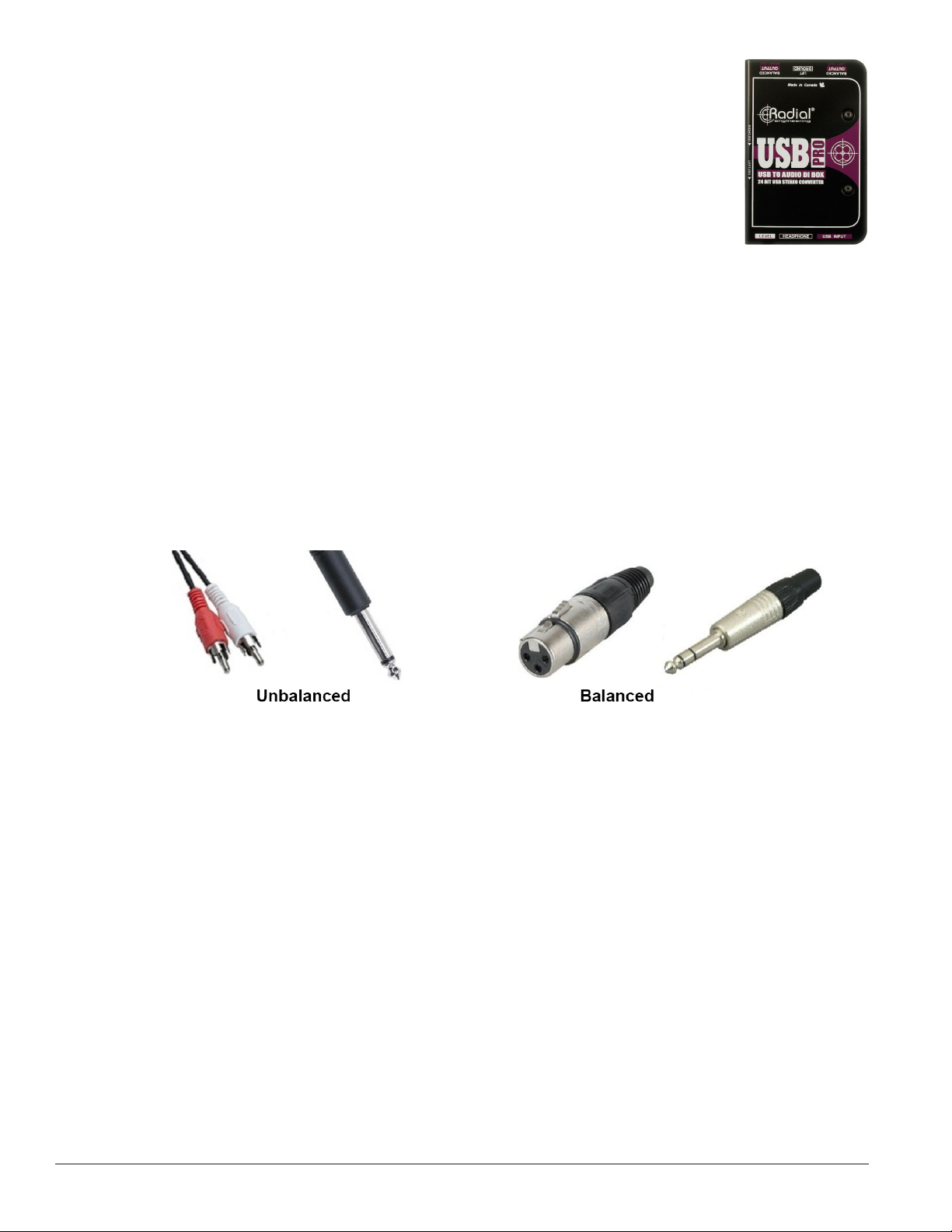
USB Audio Interface ..................................................................................................................................... 6
2.4 Signal Cables......................................................................................................................................................... 6
Section 3: Setup & Operation ............................................................................................................................... 7
3.1 Setup....................................................................................................................................................................... 7
3.2 Mixer Operation ................................................................................................................................................... 9
3.3 Wireless Mic System Operation (Optional).................................................................................................... 10
Wireless Receiver ........................................................................................................................................ 10
Single Receiver ..................................................................................................................................... 10
Network Receivers............................................................................................................................... 10
Wireless Mic & Bodypack Operation....................................................................................................... 11
3.4 Microphone Best Practices ................................................................................................................................ 12
Section 4: Maintenance & Troubleshooting ...................................................................................................... 13
4.1 Maintenance........................................................................................................................................................ 13
4.2 Troubleshooting ................................................................................................................................................. 13
Section 5: Replacement Parts ............................................................................................................................ 15
5.1 SSR-200 Components......................................................................................................................................... 15
5.2 Optional Components ....................................................................................................................................... 15
Section 6: Daktronics Exchange and Repair & Return Programs .................................................................. 17
6.1 Exchange Program ............................................................................................................................................. 17
Before Contacting Daktronics ................................................................................................................... 17
6.2 Repair & Return Program ................................................................................................................................. 18
Shipping Address........................................................................................................................................ 18
6.3 Daktronics Warranty & Limitation of Liability ............................................................................................. 18
Appendix A: Reference Drawings .......................................................................................................................... 19
Appendix B: Supplementary Manuals ................................................................................................................... 21
Appendix C: Daktronics Warranty and Limitation of Liability ............................................................................. 23

ii Table of Contents

Introduction 1
Section 1: Introduction
This manual explains the operation of the Sportsound®Rack (SSR) 100. For additional information regarding
the safety, installation, operation, or service of this system, refer to the telephone numbers listed in Section 6.
This manual is not specic to a particular installation. Project-specic information takes precedence over any
other general information found in this manual.
IMPORTANT SAFEGUARDS
• Read and understand all instructions before beginning the installation process.
• Do not drop the control equipment or allow it to get wet.
• Do not disassemble control equipment or electronic controls of the system; failure to follow this
safeguard will make the warranty null and void.
• Always turn off and/or unplug the control equipment when it is not in use. This keeps equipment
protected from power spikes and lightning.
• Never yank the power cord from the outlet. Grasp the plug and pull to disconnect.
• Do not let any power cord touch hot surfaces or hang over the edge of a table that would damage or
cut the cord. Arrange the cord with care so that it will not be tripped over.
• Inspect control equipment for shipping damage such as rattles and dents, and verify that all
equipment is included as itemized on the packing slip. Immediately report any problems to
Daktronics; save all packing materials if exchange is necessary.
• Keep equipment covered when possible to protect from dust and debris.
1.1 Resources
Figure 1 illustrates a Daktronics drawing label. The drawing
number is located in the lower-right corner of a drawing. This
manual refers to drawings by listing the last set of digits and
the letter preceding them. In the example, the drawing would
be referred to as Drawing D-1007804. All references to drawing
numbers, appendices, gures, or other manuals are presented in
bold typeface. Any drawings referenced in a particular section
are listed at the beginning of it as shown below:
Reference Drawing:
System Riser Diagram ................................................................................................. Drawing D-1007804
All drawings referenced in this manual are found in Appendix A.
Daktronics identies manuals by the DD or ED number located on the cover page. For example, this manual
would be referred to as DD2746938.
Daktronics has a searchable knowledgebase of common questions and troubleshooting tips:
www.daktronics.com/support
Visit the Daktronics Support YouTube channel to learn how to properly operate Sportsound racks:
www.youtube.com/DaktronicsSupport
Drawing Number
Figure 1: Drawing Label

2 Introduction
1.2 Daktronics Nomenclature
Most display components have a white label that lists the part number (Figure 2).
Part numbers will also appear on certain drawings. If a component is not found in the
Replacement Parts List in Section 5 use the label to order a replacement. Section 6
describes the Daktronics Exchange Policy and the Repair & Return Program. Refer to
these instructions if replacing or repairing any display component.
Main Component Labels
Part Type Part Number
Individual circuit board 0P-XXXX-XXXX
Assembly; a collection of
circuit boards 0A-XXXX-XXXX
Wire or cable W-XXXX
Fuse F-XXXX
Transformer T-XXXX
Metal part M-XXX
Fabricated metal assembly 0S-XXXXXX
Specially ordered part PR-XXXXX-X
0P-1127-0024
SN: 2465
02/19/12 Rev. 1
Figure 2: Part Label
Accessory Labels
Component Label
Termination block for
power or signal cable TBXX
Grounding point EXX
Power or signal jack JXX
Power or signal plug for
the opposite jack PXX

SSR-100 Components 3
Section 2: SSR-100 Components
2.1 Overview
Reference Drawing:
Schematic/Layout; Sportsound Rack 100.....................................................................Drawing B-1190379
Figure 3 displays the various announcer’s rack components that are visible after removing the protective
covers. Refer to Drawing B-1190379 in Appendix A for rack component and connection locations as well as a
detailed wiring schematic.
# Component Reference Supplementary Manual
1Audio Mixer Section 3.2 Rane MLM82S Operators Manual
2Wireless Receiver System Section 3.3 Shure®QLX-D®Wireless System User Guide
3I/O Panel w/ On/Off Switch N/A N/A
All supplementary manuals are listed in Appendix B.
2
Rear View
Front View
4
5
3
7
OR
Fiber Box
(outdoor) Wall Plate
(indoor)
Laptop
Interface
(optional)
Audio
Mixer
Wireless Mic System
6
Optional
1
2
3
Announcer’s
Interface
(Gen II)
1
Figure 3: SSR-100 Components (covers removed, optional equipment shown)

4 SSR-100 Components
2.2 Standard Equipment
Audio Mixer
The Rane MLM82S (Figure 4) features four balanced mono Mic/Line Inputs (XLR) with 15 VDC phantom
power and signal/overload indicators. Each of the four Mic/Line Inputs may be assigned to A, A+B or B
Outputs. Other features include:
• Four balanced stereo line inputs (TRS) with 12 dB of line gain
• Two balanced Outputs (XLR)
Announcer’s Interface
The Daktronics Announcer’s Interface (Figure 5) includes one
(1) balanced MIC output, one (1) balanced AUX input, and
headphone jacks; headphone volume control knob; and momentary
or continuous microphone activation buttons. Microphone and
headphones are provided.
Laptop Interface
This portable, durable balanced audio converter allows connection
of a laptop or mp3/music player into pro-level mixers (Figure 6).
Other features include:
• 1/8" (3.5 mm) male input
• Balanced XLR male output
• Adjustable output volume control
• Black powder-coated aluminum chassis
2.3 Optional Equipment
Wireless Microphone System
The Shure®QLX-D® is a professional UHF wireless microphone system.
Dual receivers in the audio rack allow operation of two wireless transmitters
simultaneously (Figure 7). Over 60 compatible channels per frequency
band and up to 17 compatible systems per 6 MHz TV channel are available. Automatic Frequency Selection
technology detects the clearest frequencies in the area. Other features include:
• Lockable settings
• Battery power gauges
• Effective Range: 328' (100 m) under optimal conditions
• Audio Frequency Response: 20Hz to 20kHz, ±2dB
• Total Harmonic Distortion: <0.1%
• RF Sensitivity: -97 dBm at 10-5 BER
Figure 4: Audio Mixer
Figure 5: Announcer’s Interface Kit
Figure 6: Laptop Interface

SSR-100 Components 5
High Gain Antenna Kit
The Shure®PA805 (Figure 8) is a directional antenna for increased range and
reduced interference. The “gain” of this antenna enables it to receive signals
from a greater distance than at typical “whip” type antenna. The antenna
allows for increased performance of wireless microphones with 6 db of gain.
The directional antennas may be located up to 50' (15.2 m) away from the
announcer’s rack.
Single-Muff Headset
The professional single-muff headset (Figure 9) may be used in place of the
standard announcer’s interface wired microphone and headphones. Other
features include:
• Ambient noise attenuation
• Neodymium magnet system for high reproduction precision
• Soft, circumaural ear pads
• Cardioid condenser microphone
Figure 7: Wireless Microphone & Bodypack Transmitter w/ Mute Switch
Figure 8: Directional Antenna
Figure 9: Single-Muff
Headset

6 SSR-100 Components
USB Audio Interface
The Radial®Engineering USB-Pro™ (Figure 10) provides an interface from laptop
computers to balanced outputs. Other features include:
• 24-bit, 96 kHz quality audio
• Two balanced XLR outputs (left and right)
• 3.5mm TRS headphone output
• Ground lift and mono-sum switches
2.4 Signal Cables
Cable specications are as follows:
• 5' (1.5 m) XLR cable for auxiliary audio input (part # W-1627)
• 15' (4.6 m) XLR cable between announcer’s interface and rack (part # W-2074)
• 25' (7.6 m) XLR cable from rack to ber box or wall plate (part # W-1560)
Notes:
• Keep unbalanced cable lengths under 6' (1.8 m) to prevent unwanted noise from being picked up.
Use appropriate converters, such as the LTIBLOX Laptop Interface, to convert to balanced cables
(Figure 11) for longer cable runs if necessary.
• Run audio cables away from power cables to prevent noise.
• Audio cables must be kept separate from current loop (scoreboard control) signal cables.
Figure 10: USB
Audio Interface
Figure 11: Balanced/Unbalanced Cable Comparisons

Setup & Operation 7
Section 3: Setup & Operation
3.1 Setup
Before Beginning: Place the rack on a at, sturdy surface. Remove the front and rear cover pieces by
releasing all latches; set the covers aside. Refer to the steps below and Figure 12.
1. Announcer's Interface setup is described below. For more information, refer also to the quick guide
(DD3083838) shipped with the device.
a. Connect the 2' (610 mm) XLR cable between the microphone and the MIC 1 INPUT jack.
b. Connect headphones to the 1/4" or 1/8" jack.
c. Connect the provided 12 VAC wallpack transformer to the power input jack, and then plug
the other end into a standard 120 VAC outlet. Use the tab above the power jack as a strain
relief for the power cord.
2. Connect the 15' (4.6 m) XLR cable from MIC 1 & AUX 1 on the announcer’s interface to MIC 1 &
AUX 1 OUT (A) jacks on the front of the rack.
3. Connect one end of the 2' (0.6 m) or 5' (1.5 m) XLR cable to the LTIBLOX Laptop Interface and the
other end to MIC 2. The 3.5 mm plug may be connected to the headphone jack of a laptop or MP3
player.
4. Connect the 25' (7.6 m) XLR cable between the MAIN OUT (B) jack on the front of the rack and the
SYSTEM AUDIO jack on the bottom of the ber box. If there is no ber box, the cable will typically
connect to a wall plate junction box instead.
5. Locate the 3-prong power cord in the rear of the rack and plug into a standard outlet. Ensure the ber
box (if included) also has power.
6. Turn on the power strip.
7. Switch the SIGNAL to ON.
Follow the above steps in reverse order to power down the system. Place all accessories in a secure location to
avoid damage/theft.
Note: Ensure any optional antennas connected into the jacks off to the sides of the wireless receiver(s) are
perpendicular to the rack and angled outward at ~45°., as shown in Figure 3.
Alternately, coaxial cable from the optional high gain antenna kit may be connected into these jacks.
The antennas should be located within 50' (15.2 m) of the rack, using desktop stands or mounted to the
ceiling. Refer to the Shure®Model PA805 Directional Antenna User Guide for more information.

8 Setup & Operation
2
Rear View
Front View
4
5
3
7
OR
Fiber Box
(outdoor) Wall Plate
(indoor)
Laptop
Interface
(optional)
Audio
Mixer
Wireless Mic System
6
Optional
1
2
3
Announcer’s
Interface
(Gen II)
1
Figure 12: Rack Setup w/ Announcer's Interface (Gen II)

Setup & Operation 9
3.2 Mixer Operation
Basic instructions are described below. For more information about mixer
operation, refer to the Rane MLM82S Operators Manual.
• Ensure all source equipment is turned on and operational (refer to
appropriate pages).
• For each input channel (source) in use, verify the following settings
as shown in Figure 13:
– SIG/OL light is green; if this light is red, decrease the level
– ASSIGN is set to “A+B” or “B”
Note: Inputs set to “A” will only be heard through the announcer’s
console headphones. This may be used to listen to each input without
interrupting the main mix.
• When the input is in MONO mode, the signal goes to both “A” and “B”
outputs. The amber LED illuminates when in MONO mode (Figure 14).
When not in MONO mode, the input signal goes to the “B” output (as
set in the factory).
• Adjust MASTER VOLUME “B” level (Figure 15) to achieve the nal
output. If the OL light is red, decrease the level.
Remember: Bad input = bad output. No adjustment on the mixer can make a
poor source sound better. For best results, be sure to use high-quality audio les
from your MP3 player or laptop, and set the device to near full volume.
Figure 13: Input Level Adjustment
Figure 14: MONO Input
Figure 15: MASTER Output

10 Setup & Operation
3.3 Wireless Mic System Operation (Optional)
Basic instructions are described below. For more information about wireless mic system operation, refer to
the Shure®QLX-D®Wireless System User Guide.
Note: For systems built prior to November 2014, refer to the Shure®ULX®Wireless System User Guide
for setup and operation instructions.
Wireless Receiver
The unit displays the following information (Figure 16):
a. Transmitter Battery Life
b. TV Channel
c. Frequency
d. Group Number
e. Channel Number
f. RF Signal Strength
g. Transmitted Audio Level
h. Gain Level
Single Receiver
1. Ensure all transmitters are powered off. Press the power button to turn on the receiver if it is not
already on.
2. Press menu until “scan” displays on the LCD.
3. Press enter to start frequency scan. When scan is complete, Group and Channel will display on the
LCD.
Network Receivers
1. Ensure all transmitters are powered off. Turn on all receivers and wait one minute to allow time to
connect to the network.
2. Press menu on one receiver until group number ashes.
3. Use the arrow buttons to select a group to scan.
4. Press enter, wait for channel, and then press enter again
5. Press menu until “network scan” displays on the LCD.
6. Press enter twice to deploy channels to other receivers.
Note: Perform a scan on all of the wireless units just minutes before the game! If a scan is performed too far
ahead of time, frequencies set up by the media later on may interfere with previously congured wireless
microphone settings.
PowerIR Window
a
e
b c
dg
fh
Power
ON/OFF
Power
ON/OFF
IR Window
Figure 16: Wireless Receiver LCD & Controls

Setup & Operation 11
Wireless Mic & Bodypack Operation
1. Open the battery cover. Insert new or fully-charged AA batteries prior to each use, and always have
spares on hand.
2. Power on the transmitter device (Figure 17).
3. Hold the transmitter device up close to one receiver in the rack, ensuring the infrared (IR) windows
are aligned.
4. Press sync on the receiver; “good” will display if sync was successful.
5. Repeat steps 1-4 to pair another transmitter device with an additional receiver (if present).
Note: Plug the referee mute switch into the jack on top of the bodypack unit and plug headphones/
lapel mic into the referee mute switch.
Verify Reception: With a transmitter and the receiver both turned on and having matching GROUP and
Channel numbers, the RF meter on the receiver should be indicating signal. Speak into the microphone and
the TX AUDIO meter should indicate signal presence.
Additional Tips:
• Perform a group and channel scan to obtain the best available channel for microphones.
• Check that battery levels are adequate to prevent wireless equipment from powering off during use.
• Program one microphone per receiver; multiple microphones on the same channel will cause
interference and microphones will drop out.
• Always use quality batteries to prevent battery leaks that can corrode and shorten the life of the
equipment.
PowerIR Window
a
e
b c
dg
fh
Power
ON/OFF
Power
ON/OFF
IR Window
Figure 17: Wireless Mic & Bodypack Controls

12 Setup & Operation
3.4 Microphone Best Practices
• Keep handheld microphones 4-6 inches (102-152 mm) from the mouth (about the width of a hand).
“P-pops” are loud sounds created by the release of breath when saying letters like “p” or “b”. To
avoid P-pops, keep handheld microphones below the mouth, angled toward the nose at a 45° angle.
Do not point the front of the microphone straight at the mouth.
• Position headset microphones as close to the mouth as comfortable.
• The referee bodypack kit includes both headset and lapel microphones. In general it is recommended
to use the headset mic for best results. If the lapel mic is desired, clip it onto a lapel, as close to the
center of the chest as possible.
• The softer or louder the speaker’s voice, move the microphone closer or further away, respectively.
• Never hit or intentionally blow into a microphone as it could quite easily be damaged.

Maintenance & Troubleshooting 13
Section 4: Maintenance & Troubleshooting
4.1 Maintenance
• Unplug rack (and ber box, if included) from power during periods of non-use.
• Store equipment in a clean dry place free from moisture, debris, and extreme temperatures.
• Keep announcers rack and equipment covered from dust and debris when not in use.
• Clean equipment annually or as needed using electronic equipment duster and a dry cloth.
4.2 Troubleshooting
This section lists potential problems with the system, indicates possible causes, and suggests corrective action.
This list does not include every possible problem, but it does represent some of the more common situations
that may occur. If individual components fail to work, refer to troubleshooting sections in the manufacturers’
manuals. If the problem persists, please contact Daktronics for assistance.
Symptom/Condition Possible Cause Potential Solution
No power lights illuminated
on rack equipment
Rack power strip switch is in the OFF
position
Flip the rack power strip switch to the ON
position
Rack is plugged into dead wall receptacle Verify the rack is plugged into live wall
receptacle
No audio exiting the rack
SIGNAL switch is in the OFF position Flip switch to the ON position
No audio present at mixer
Verify audio source is outputting signal
to mixer and gain knobs are set to an
appropriate level (mixer signal indicator
lights should be illuminated green)
Announcer’s interface
microphone signal does not
appear at mixer
Announcer's interface does not have
power
Verify the interface is plugged into live
wall outlet
Announcer’s interface is not plugged into
appropriate inputs on the rack
Plug announcer’s interface into AUX 1
OUT (A) and MIC 1 on front of rack
Improper mixer slider settings for MIC 1 Adjust MIC 1 level knob
The announcer’s interface “push-to-talk”
button is not being pressed
Hold the MOMENTARY button while
speaking into the microphone
Announcer only hears self
through headphones
Switch on the announcer’s interface is
set to MIC ONLY Switch to AUX IN
Announcer hears nothing
through headphones
Announcer’s interface is not plugged into
appropriate inputs on the rack
Plug announcer’s interface into AUX 1
OUT (A) and MIC 1 on front of rack
AUX 1 OUT (A) settings are improperly
set on mixer Check AUX 1 OUT (A) mixer settings
Announcer’s interface HEADPHONE
VOLUME is turned down
Turn HEADPHONE VOLUME knob to an
appropriate level
Announcer’s mic muting
circuit does not work No phantom power from mixer
Ensure 15V PHANTOM POWER button
on back of mixer is depressed
(Gen I Announcer's interface only)

14 Maintenance & Troubleshooting
Symptom/Condition Possible Cause Potential Solution
For Wireless
No signal present at mixer
from wireless microphones
The battery is not installed properly in the
transmitter Reinstall the battery properly
The battery is not providing full power Charge or replace battery
The transmitter is not switched to the ON
position Switch the transmitter to the ON position
The transmitter and receiver are set to
different channels Set to same channel
Interference on wireless
equipment
Competing RF equipment within
frequency band
1. Scan for clearest group/channel on
microphone receiver.
2. Switch wireless receiver and
transmitter to an available clear
channel. (Section 3.3)
Low audio signal from
wireless device
Improper gain adjustment on mixer input Set proper mixer input gain levels
Improper gain adjustment on transmitter
output
Set proper transmitter output gain levels
(refer to Shure®Wireless System User
Guide)

Replacement Parts 15
Section 5: Replacement Parts
5.1 SSR-200 Components
Part Description Part Number
Announcer’s Interface 0A-1534-0093
Announcer's Interface; Push-to-Talk A-3698
Desk Microphone Stand A-1954
Headphones, ¼" Phone A-1962
Dynamic Vocal Microphone A-2790
Wallpack Transformer, 12VAC; 6' Cord T-1118
2' XLR Cable W-1917
15’ Cable, Announcer Box to Mixer W-2074
Rane MLM82S Mixer A-1960
6 Outlet Power Strip A-2840
LTIBLOX Laptop Interface A-2755
Cable, 25’ XLR M to F W-1560
Cable, 5’ XLR M to F W-1627
Cable, 2’ XLR M to F W-1917
5.2 Optional Components
Part Description Part Number
High Gain Antenna Kit 0A-1340-0325 (2)
Desk Microphone Stand A-1954
Microphone Stand, Flange Mount A-2888
13” Gooseneck A-2889
Passive Directional Antenna, 470-952 MHz A-3124
50’ Coaxial Antenna Cable w/ BNC W-2476
Referee Headset Microphone A-1972
Single Muff Microphone Headset A-2382
USB Audio Interface A-2493
Referee Mute Switch A-3122
Referee Lapel Microphone A-3589
Wireless Receiver For Band G50 A-3590
Wireless Receiver For Band H50 A-3591
Wireless Receiver For Band J50 A-3592
Wireless Handheld For Band G50 A-3593
Wireless Handheld For Band H50 A-3594
Wireless Handheld For Band J50 A-3595
Wireless Bodypack For Band G50 A-3596
Wireless Bodypack For Band H50 A-3597
Wireless Bodypack For Band J50 A-3598
Wireless Accessories
Passive Antenna Combiner A-3121
Black Cloth Pouch for Bodypack A-3123

This manual suits for next models
1
Table of contents
Other Daktronics Recording Equipment manuals

Daktronics
Daktronics Sportsound SSR-300 User manual

Daktronics
Daktronics LiveBook GFX User manual

Daktronics
Daktronics SPORTSOUND SSR-100 GEN II User manual

Daktronics
Daktronics SPORTS WIRE 4000 INTERFACE User manual

Daktronics
Daktronics DM-100 Gen III User manual

Daktronics
Daktronics Sportsound Gen II User manual

Daktronics
Daktronics 5000 Series User manual

Daktronics
Daktronics VIP-4060 User manual

Daktronics
Daktronics Sportsound SSR-200 User manual

Daktronics
Daktronics Sportsound SSR-AM User manual