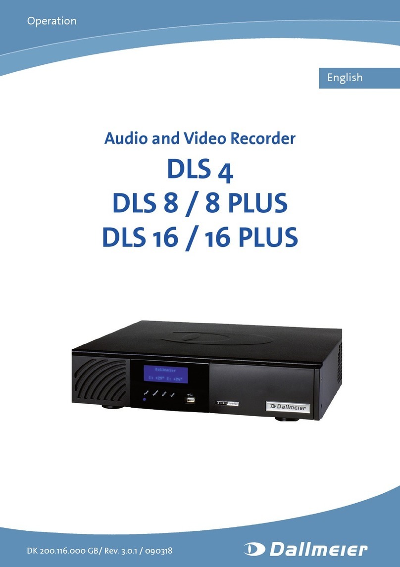
dallmeier DLS 4 Operating and maintenance instructions

Installation and Configuration
3.0.2 / 090504
English
Audio and video recorder
DLS 4
DLS 8 / 8 PLUS
DLS 16 / 16 PLUS

DLS 4 / DLS 8 / 8 PLUS / DLS 16 / 16 PLUS
2Dallmeier electronic
Information about copyright, trademarks, design patents
© 2009 Dallmeier electronic
All rights reserved. This document may not be copied, photocopied, reproduced, translated, transferred
to an electronic medium or converted to a machine-readable form either whole or in part without rst
receiving written permission from Dallmeier electronic GmbH & Co.KG.
We reserve the right to make technical modications.
The manufacturer accepts no liability for damage to property or pecuniary damages arising due to minor
defects of the product or documentation, e.g. print or spelling errors, and for those not caused by intenti-
on or gross negligence of the manufacturer.
Dallmeier electronic GmbH & Co.KG
Cranachweg 1
D 93051 Regensburg, Germany
www.dallmeier-electronic.com
All trademarks identied by ® are registered trademarks of Dallmeier electronic.
Third-party trademarks are named for information purposes only.
Dallmeier electronic respects the intellectual property of third parties and always attempts to ensure the
complete identication of third-party trademarks and indication of the respective holder of rights. In case
that protected rights are not indicated separately, this circumstance is no reason to assume that the
respective trademark is unprotected.

DLS 4 / DLS 8 / 8 PLUS / DLS 16 / 16 PLUS
3Dallmeier electronic
Table of contents
1 This document 8
1.1 Validity 8
1.2 Documentation 8
1.3 Convention 8
2 For your safety 10
3 General instructions 12
3.1 Scope of delivery 12
3.2 Transportation and packaging 12
3.3 Warranty 12
4 Installation and mounting 13
4.1 General Requirements 13
4.2 Stand-alone installation 13
4.2.1 Requirements 13
4.2.2 Installation 13
4.3 Rack mounting 14
4.3.1 Requirements 14
4.3.2 Mounting 15
5 Connection 16
5.1 Connection assignment 16
5.2 Power supply 17
5.3 Cameras 17
5.4 Monitors 18
5.5 Audio 18
5.6 Mouse and keyboard 19
5.7 Contact IN 19
5.7.1 Global contacts 19
5.7.2 Contacts for individual cameras 20
5.8 Relay OUT 21
5.9 Optional peripheral devices 22
6 Start-up and login 23
6.1 Start-up 23
6.2 Login variants 23
6.2.1 Login in basic conguration 23
6.2.2 Login at group level 24
6.2.3 Login at user level 25
7 Basic settings 26
7.1 Language 26
7.2 System time 26
7.2.1 Set the time 26
7.2.2 Time server 27
7.2.3 USB radio clock 28
7.3 System security 29
7.4 Options 29
7.4.1 Alarm duration 30
7.4.2 Test modes 30
7.4.2.1 Compare 31

DLS 4 / DLS 8 / 8 PLUS / DLS 16 / 16 PLUS
4Dallmeier electronic
7.4.2.2 Performance 32
7.4.2.3 Tracking 32
7.4.3 Keyboard mode 33
7.4.4 Single split replay 33
7.4.5 Playback monitor 34
7.4.6 System messages 34
7.4.7 Assistant mode 35
7.4.8 Recording timeout 36
7.4.9 OSD texts 37
7.4.10 Logging 39
7.4.11 Simple Export 39
7.4.12 Recording monitoring 40
8 Recording setting 41
8.1 Track mode 41
8.1.1 Standard 42
8.1.1.1 Recording 42
8.1.1.2 Modications 42
8.1.1.3 Track types 42
8.1.1.4 Recording modes 43
8.1.2 Manual 43
8.1.2.1 Recording 43
8.1.2.2 Modications 44
8.1.2.3 Track types 44
8.1.2.4 Recording modes 44
8.1.3 Automatic 44
8.1.3.1 Recording 45
8.1.3.2 Modications 45
8.1.3.3 Track types 45
8.1.3.4 Recording modes 45
8.1.4 Change 45
8.2 Connection 46
8.3 Basic conguration 46
8.3.1 Camera and track name 47
8.3.2 Camera timer 47
8.3.3 Tracks timer 49
8.3.4 Areas 50
8.3.4.1 Active areas 50
8.3.4.2 Private Zones 51
8.4 Recording mode 52
8.4.1 Manual and automatic mode 53
8.4.1.1 Permanent 53
8.4.1.2 Motion 54
8.4.1.3 Contact 55
8.4.2 Standard mode 56
8.4.2.1 Permanent 56
8.4.2.2 Motion 57
8.4.2.3 Contact 58
8.5 Video quality 59
8.5.1 Manual and automatic mode 59
8.5.2 Standard mode 61
8.5.3 Optional conguration 61
8.5.3.1 Direct conguration 61
8.5.3.2 Auto conguration 62
8.6 Activation 63
8.7 Video memory 63
8.7.1 Standard 63

DLS 4 / DLS 8 / 8 PLUS / DLS 16 / 16 PLUS
5Dallmeier electronic
8.7.1.1 Longplay tracks 63
8.7.1.2 Secure tracks 64
8.7.2 Manual 65
8.7.3 Automatic 65
8.8 Other functions 66
8.8.1 Audio 66
8.8.2 Dual Streaming 66
8.8.3 SmartFinder 66
8.8.4 Camera control 68
9 Display settings 69
9.1 Recorder and camera description 69
9.2 Splitter 70
9.2.1 Automatic assignment 71
9.2.2 Manual assignment 71
9.3 Sequencer 72
9.3.1 VGA display sequence 72
9.3.2 CVBS display sequence 73
9.3.3 Display frame rate 74
10 Network and PAS 75
10.1 Ethernet 75
10.2 PSTN/Terminal Adapter 76
10.3 Alarm hosts 76
10.3.1 Selection and name 76
10.3.2 Connection 77
10.3.3 Alternative alarm host 78
10.3.4 Connection check 79
10.3.5 Messages 80
10.3.6 Timer 83
10.3.7 Activation 84
10.3.8 EBÜS 84
10.4 Parameter backup 85
10.4.1 System name 85
10.4.2 Export 86
10.4.3 Import 86
11 Serial Interface 87
11.1 Setting 87
11.2 Functions 87
12 Contact IN 89
12.1 Global and camera-related contacts 89
12.2 Make and break contact functions 89
12.3 Setting 90
12.4 Functions 91
12.5 Conguration of camera-related contacts 93
13 Relay OUT 95
13.1 Setting 95
13.2 Functions 95
14 Congurationofoptionalperiphery 100
14.1 Printers 100
14.1.1 Create printer 100
14.1.2 Set printer 101
14.2 DIS control 102

DLS 4 / DLS 8 / 8 PLUS / DLS 16 / 16 PLUS
6Dallmeier electronic
14.3 Storage System 102
14.4 Weather server 103
14.5 Dallmeier network interface 103
14.5.1 DNI - external system 103
14.5.2 DNI - camera control 105
14.6 UPS 106
14.6.1 Serial UPS 106
14.6.2 UPS conguration 107
14.7 Card reader 107
14.8 VSC 108
15 Congurationofoptionalfunctions 109
15.1 Signal loop through 109
15.2 UTC camera conguration 109
15.2.1 Required settings 110
15.2.2 Control panel 110
15.2.3 Zoom function 111
15.2.3.1 Save zoom factor and position 111
15.2.3.2 Enter name for position 112
15.2.4 Congure camera 112
15.2.4.1 Functions 113
15.2.4.2 Close menu and save conguration 113
15.2.4.3 Save camera conguration for direct selection 114
15.2.5 Reset camera settings 115
15.2.6 End UTC camera conguration 115
15.3 PRemote 115
15.4 Serial camera control 116
16 HDD management 118
17 User management 120
17.1 Edit groups 120
17.1.1 Issuing permissions 120
17.1.2 Change group name or login 121
17.1.3 Dene or change passwords 122
17.1.4 Dual-control login 122
17.2 Login as user 123
17.2.1 Create users 123
17.2.2 User rights 124
17.2.3 Change user password 124
17.2.4 Delete users 125
17.2.5 User options 125
18 Service 127
18.1 Activation 127
18.2 Update 127
19 System parameters 129
19.1 Default system parameters 129
19.2 Parameter export 129
19.3 Parameter import 130
20 HDD replacement 131
20.1 Conditions 131
20.2 Localization of the HDD 132
20.3 Replace the HDD 132

DLS 4 / DLS 8 / 8 PLUS / DLS 16 / 16 PLUS
8Dallmeier electronic
1 This document
1.1 Validity
This document applies to the audio and video recorder DLS 4 / DLS 8 / DLS 8 PLUS / DLS
16 / DLS 16 PLUS. It has been produced on the basis of version 6.3.0 (software).
The descriptions in this document apply to all above-mentioned models. For simplication
reasons, the term "DLS" is thus used. If text passages require distinctions to be made bet-
ween the devices, the complete device name will be mentioned.
1.2 Documentation
Commissioning
The document entitled Commissioning contains the most important steps for the connection
and commissioning of the device.
Operation
The document entitled Operation contains detailed descriptions on how to operate the unit.
General information on the appropriate use and maintenance is also provided.
The target audience of this document is the operator of the unit ("user"). No special technical
knowledge is required.
Store this document in an accessible location near the product and keep it in readable con-
dition. Pass on this document to each successive owner or user of the product.
InstallationandConguration(thisdocument)
The document entitled Installation and Commissioning contains detailed descriptions
of the installation, connection, commissioning and conguration of the unit. Safety notes,
general information and technical data are additionally provided.
The target audience of this document is exclusively specially trained and authorized pro-
fessionals ("installers").
1.3 Convention
This document contains various warning words and symbols that indicate potential sources
of danger. Various symbols and formats are used to maintain the clarity of the document.
DANGER
The warning word DANGER denotes an immediate danger that
may cause death or serious injury if it is not averted.
WARNING
The warning word WARNING denotes a possible danger that
may cause death or serious injury if it is not averted.
CAUTION
The warning word CAUTION denotes a possible danger that
may cause minor injury if it is not averted.

DLS 4 / DLS 8 / 8 PLUS / DLS 16 / 16 PLUS
9Dallmeier electronic
IMPORTANT
The word IMPORTANT denotes information for preventing
damage, incorrect congurations or incorrect actions.
NOTE
A NOTE offers information on principles, special features and
efcient procedure as well as general recommendations.
Expression Expressions in bold and italics generally indicate a control ele-
ment on the device (switches or labels) or on its user interface
(buttons, menu entries).

DLS 4 / DLS 8 / 8 PLUS / DLS 16 / 16 PLUS
10Dallmeier electronic
2 For your safety
Only use this unit if it is technically in proper working order, to the intended purpose and
while keeping safety and potential dangers in mind. Have malfunctions or damages elimi-
nated immediately!
Appoint a professional
Installation, mounting, connection, start-up and conguration of the unit may only be carried
out by trained and authorized professionals (installers).
Unless otherwise expressly specied, this also applies to the maintenance, testing and repair.
In doing do the regulations of the DIN VDE 0701 series of standards (repair, modication
and inspection of electrical appliances) must be followed in addition.
Read and pay attention to the documents
Carefully and completely read the documents included in delivery. Always pay attention to
the provided instructions, notes and warnings.
Regulations surveillance systems
The use of video and audio surveillance systems is strictly regulated in most countries.
Therefore, inform yourself on laws and regulations that govern individual applications be-
fore using the unit. Ensure compliance with these laws and regulations and also observe
regulations regarding data, working and environmental protection.
Regulations data protection
This unit can store data that may be subject to data protection. The collecting, recording,
processing or disclosure of such data may be forbidden and thus have legal consequences.
Therefore, inform yourself on data protection laws and regulations that govern individual
applications before using the unit. Ensure compliance with this laws and regulations.
Donotmakemodications
Do not make any modications to the unit (neither to the software nor the hardware) without
consulting Dallmeier electronic. Improper modications can cause malfunctions or damages.
Dallmeier electronic accepts no liability for damages resulting from unauthorized or improper
modications to the unit.
Protection against condensation water
If the unit is brought from a cold to a warm environment, condensation water can form inside
the unit. Short-circuits may then lead to damage to the system. Wait up to 8 hours for the
unit to reach room temperature before starting it up.
Observe the rated voltage
The unit can be damaged or destroyed by the application of an incorrect voltage.
The mains voltage must always match the rated voltage of the unit. The rated voltage is
specied on the rating plate of the unit.
Observe ratings
Unsuitable ambient conditions and improper installation (mainly too high ambient tempera-
ture and insufcient ventilation) may reduce the unit’s life cycle. Ensure compliance with the
stated operating conditions (see technical data), requirements at the installation site and, if
applicable, maintenance regulations.
DLS 4 / DLS 8 / 8 PLUS / DLS 16 / 16 PLUS
11Dallmeier electronic
Expansion components/peripheral devices
Use only expansion components conforming with the technical data of the unit. Inappropriate
peripheral devices may result in the violation of local laws and regulations and damages
to the unit. Furthermore, the use of peripheral devices that are not certied by Dallmeier
electronic results in loss of warranty. In case of doubt, contact the sales partner responsible
for your area.
Do not move while in operation
Strong vibrations can cause damage to the unit, in particular to the hard disk(s). Therefore,
do not bump the unit or move it in a jerky motion while in operation. Instruct the cleaning
personnel accordingly if necessary!
Do not open the unit
Do not open the housing of the unit. There are no components inside the unit that require
maintenance by the user. The inspection, maintenance and repair with an open housing
must only be carried out by trained and authorized professionals (installer).
Penetration of foreign bodies and liquids
No objects or liquids may be allowed to get into the device. In this case, immediately dis-
connect the unit from the power supply (pull out the power plug). Please contact the sales
partner responsible for your area.
Measures to be taken in the event of damage and burnt smell
If you notice burnt smell or formation of smoke from a unit, immediately disconnect it from
the power supply (pull out the power plug). Please contact the sales partner responsible
for your area.
Disposal
Disconnect the unit from the power supply. Remove all connected units and system com-
ponents. Return the unit to your respective sales partner.

DLS 4 / DLS 8 / 8 PLUS / DLS 16 / 16 PLUS
12Dallmeier electronic
3 General instructions
3.1 Scope of delivery
Included in the standard scope of delivery is:
1 x Recorder including HDDs (as ordered)
1 x Dallmeier mouse (optical, small version)
1 x 12V power supply unit including mains cable (differs from country to country)
1 x 9-pin D-SUB interfaces with housing
2 x 18 pin. Weidmüller Plug connector
1 x 2 pin. Weidmüller Plug connector
1 x Audio cable frame (2 x for 16-channel recorder)
1 x PS/2 Y-adapter
1 x Spare set of lters (5 lters)
1 x "Installation and Conguration" documentation (CD)
1 x "Operation" documentation (CD)
1 x Quick guide “Commissioning" (printed)
The scope of delivery may differ depending on the ordered equipment or device variant.
The device’s range of functions depends on the ordered equipment or device variant and
may therefore not correspond with this document’s content. Certain functions and features
may require an activation that is subject to costs.
3.2 Transportation and packaging
Store the original packaging for transportation at a later date. Dallmeier electronic is not
responsible for damage resulting from unprofessional/improper transportation. The goods
should only be shipped in their original packaging.
If the original packaging is no longer available, ensure that the packaging used sufciently
protects the unit against damage, moisture, heat and cold.
3.3 Warranty
The terms and conditions valid at the signing of the contract apply.

DLS 4 / DLS 8 / 8 PLUS / DLS 16 / 16 PLUS
13Dallmeier electronic
4 Installation and mounting
The DLS is designed for stand-alone operation. As an option it may also be installed in a
19“ standard rack.
4.1 General Requirements
Unfavorable local conditions may shorten the life of the product or lead to malfunctions.
Do not operate DLS at places
lwith large scale dust and dirt
l with steam or oil vapors (e.g. kitchen)
lwith direct sunlight
lwith unsuitable ambient temperatures
l near sources of strong radiation (e. g. X-rays, radio transmitters or magnetic elds)
l with corrosive surroundings (e.g. gases or salt water)
l with insufcient ventilation (e. g. closed cabinet)
Comply with all the safety instructions and technical data.
4.2 Stand-alone installation
The DLS may be freely positioned in a place respecting the requirements mentioned above.
Attention should be paid to the fact that all connections are freely accessible.
4.2.1 Requirements
Computer room
This device is not for use in a computer room as dened in the „Standard for Protection of
Electronic Computer/Data Processing Equipment, ANSI/NFPA 75“.
Secured room
Manipulation and sabotage danger. A stand-alone installation should be made in secured
rooms with restricted access only.
Socket-outlet
The used socket-outlet has to be installed near the device. It has to be easily accessible.
4.2.2 Installation
ØDo not place the DLS upside down.
ØEnsure a stable and horizontal surface.
Ø Ensure sufcient ventilation with 4 inch free space on the front, rear and right side.

DLS 4 / DLS 8 / 8 PLUS / DLS 16 / 16 PLUS
14Dallmeier electronic
Fig. 4-1
ØEstablish the required connections as described in the following.
Ø Start-up and login for conguration as described in the following.
4.3 Rack mounting
The DLS can be installed in a 19“ standard rack using two 19’’ mountings (option).
4.3.1 Requirements
Elevated operating ambient
The operating ambient temperature in a multi-unit rack may be greater than the room ambient.
Ensure that the maximum ambient temperature in the rack complies with the requirements
specied in the technical data.
Reducedairow
The air ow in a (closed) rack may be reduced. Ensure that the amount of air ow required
for save operation is not compromised. Ensure sufcient ventilation with 4 inch free space
on the DLS front, rear and right side.
Mechanical loading
Mechanical loading may damage the device. Do not mount the DLS upside down. Ensure
a stable and horizontal mounting.
Circuit overloading
The device can be damaged or destroyed by the application of an incorrect voltage. The
mains voltage must always match the rated voltage. The rated voltage is specied on the
nameplate.

DLS 4 / DLS 8 / 8 PLUS / DLS 16 / 16 PLUS
15Dallmeier electronic
Reliable earthing
Ensure a reliable earthing of the DLS. Use power strips when other supply connections than
direct connections to the branch circuit are being used.
4.3.2 Mounting
ØRemove the four side housing screws.
Fig. 4-2
ØPlace the two 19“ mountings against the housing.
Fig. 4-3
ØSecure the 19“ mountings to the housing using the removed screws.
Ø Install the device in the 19“ rack.
IMPORTANT
Follow the instructions supplied by the rack manufacturer.
ØDo not mount the DLS upside down.
ØEnsure a stable and horizontal mounting.
Ø Ensure sufcient ventilation with 4 inch free space on the DLS front, rear and right
side.
ØEstablish the required connections as described in the following.
Ø Start-up and login for conguration as described in the following.

DLS 4 / DLS 8 / 8 PLUS / DLS 16 / 16 PLUS
16Dallmeier electronic
5 Connection
The following describes special features for connecting the basic peripherals. See also the
technical data in the annex.
Information about the connection and conguration of optional peripherals is provided in
separate sections.
NOTE
Before connecting the device, ensure that the recorder and the
peripherals are disconnected from the power supply.
5.1 Connection assignment
NOTE
The number of connections can differ depending on the ordered
equipment or device variant. The following description relates
to a device with full equipment.
1 12V IN (2-pin ODU jack)
2 Serial interface COM2 (9-pin D-SUB)
3 Serial interface COM1 (9-pin D-SUB)
4 Video output 1 (BNC)
5 Video output 2 (BNC)
6 VGA output (15-pin mini-D-SUB)
7 LAN connection (RJ 45)
8 4 x USB 2.0 connection (Type A)
9 PS/2 connection (Mouse + Keyboard via Y-cable)
10 Audio IN channel 1-8 (15-pin D-SUB)
11 Audio IN channel 9-16 (15-pin D-SUB)
17161514
1 2 3 4 5 6 7 8 9 18 19
131211102021
Fig. 5-1: Rear view (fully equipped device)

DLS 4 / DLS 8 / 8 PLUS / DLS 16 / 16 PLUS
17Dallmeier electronic
12 Audio OUT 1 Live and playback (3,5 mm phone jack)
13 Audio OUT 2 Live and playback (3,5 mm phone jack) (inaktiv)
14 Video IN C1 – C16 (BNC)
15 Serial interface RS485 (2-pin Weidmüller pin strip)
16 Contact IN (18-pin Weidmüller pin strip)
17 Relay OUT (18-pin Weidmüller pin strip)
18 HDD1 interchangeable drawer unit
19 HDD2 interchangeable drawer unit
20 Line/AUX IN intercom (3,5 mm phone jack)
21 Audio OUT intercom (3,5 mm phone jack)
5.2 Power supply
The DLS is powered with the required voltage of 12V DC by a PSU (power supply unit).
This PSU is able to absorb shortvoltageuctuations and therefore to keep the recorder
from rebooting or shutting down.
In order to absorblongervoltageuctuationsthe DLS has to be powered with a suitable
uninterruptible power supply (UPS). These devices allow the bridging of a uctuation longer
than 100 ms, according to the DIN EN 50130-4 requirements.
IMPORTANT
The DLS must be connected to a UPS in order to meet the DIN
EN 50130-4 requirements.
5.3 Cameras
The type and number of video inputs may vary depending on the device version and addi-
tional enabling.
l 4 analog cameras (C1-C4)
l 8 analog cameras (C1-C8)
l 16 analog cameras (C1-C16)
The analog video inputs on the recorder are arranged on the connection plate (14).
ØConnect the video cables to the requisite video inputs C1-C16.
WARNING
Danger of death from electric shock caused by lightning.
Video cables must not be connected or disconnected during
a storm.

DLS 4 / DLS 8 / 8 PLUS / DLS 16 / 16 PLUS
18Dallmeier electronic
Please note that in the basic conguration, all analog video inputs on the recorder are ter-
minated. If a camera signal is forwarded to an optional device (signal loop), the termination
must be cancelled (see section entitled Congurationofoptionalperiphery).
5.4 Monitors
For connecting a monitor a distinction must be made between the various video outputs
(CVBS and VGA) and their respective functions.
VGA
The VGA monitor is connected using the VGA output (6). The VGA monitor can provide
various functions depending on the operating mode of the recorder:
Sequencer/Livemode
Display live pictures
Playback/Live mode
Display live pictures
Camera control
Display of tracks (changing to playback mode)
Display conguration dialogs (GUI – graphic user interface)
Playback mode
Playback
Track evaluation
Picture export and printing
Playback control (GUI – graphic user interface)
CVBS
Two CVBS monitors can be connected using video outputs M1 and M2.
Regardless of the recorder’s operating mode, only live pictures are output to these video
outputs at all times. The CVBS monitors can be used as pure control monitors for the se-
quencer / live mode. In addition, however, the denition of an individual display sequence
from the various cameras is possible (see section entitle Display settings / Sequencer).
The display of the recorder’s GUI (conguration and playback) and on-screen displays (OSD
texts, time and camera name) is not possible.
5.5 Audio
Audio IN
The camera’s audio channels are connected to the audio inputs 10 and 11 (15-pole D-SUB)
using a cable rack. Please note the labels on the cable rack.
Audio OUT
The audio out allways refers on the current split.

DLS 4 / DLS 8 / 8 PLUS / DLS 16 / 16 PLUS
19Dallmeier electronic
5.6 Mouse and keyboard
The mouse and keyboard can be connected either to a USB port or to the PS/2 port.
USB
Ø Connect the mouse and / or keyboard to any USB port (8).
PS/2
Ø Connect the mouse and / or keyboard to the Y-cable.
Ø Connect the Y-cable to the PS/2 port (9).
5.7 Contact IN
The Contact IN interface (16 and 17) allows various recorder functions to be started and
controlled by external devices.
The following specications apply for all contact inputs:
l Interfering pulses < 10 ms are ltered out
l Contact input must be < 1V for low level at 1 mA
lVdS calms a contact duration of min. 200 ms for alarm systems
Proceed as follows to connect the contact output on an external device:
ØUse the supplied 18-pin Weidmüller plug connector.
ØConnect the contact output on the external device to the plug connector.
Ø Align the plug connector correctly (routing).
ØCheck that the assignment is correct.
Ø Connect the plug connector to the 18-pin plug strip (16) on the recorder.
Regarding the contact inputs, a differentiation is made between contacts for individual ca-
meras and global contacts.
5.7.1 Global contacts
Fig. 5-2: Global contact inputs

DLS 4 / DLS 8 / 8 PLUS / DLS 16 / 16 PLUS
20Dallmeier electronic
Contact inputs G1 to G6 are known as global contacts.
The outer pins on the plug connector strip are connected to ground. The pins on contacts
G1 to G6 are arranged from left to right.
In contrast to the camera-related contact inputs, the global inputs are not pre-assigned. The
function that the contact should have can be set using Setup > Interfaces > Contact IN.
5.7.2 Contacts for individual cameras
Contact inputs 1 to 16 are known as camera-related contact inputs.
The outer pins on the plug connector strip are connected to ground. The pins on contacts
1 to 16 are arranged from left to right.
The function that should be initiated by making contact inputs 1-16 is preset to Camera star.
Therefore the recording of the relevant camera is started if the required recording settings
have also been made.
Make the required recording settings under Setup > Recording > Cameras (see also the
chapter entitled Recording settings).
The function initiated by the contact input can be changed under Setup > Interfaces >
Contact IN.
Fig. 5-3: Pin assignment of lobal contact inputs
Fig. 5-4: Camera-related contact inputs
Fig. 5-5: Pin assignment of camera-related contact inputs
Other manuals for DLS 4
1
This manual suits for next models
4
Table of contents
Other dallmeier Measuring Instrument manuals

dallmeier
dallmeier DMS 2400 MK3 User manual

dallmeier
dallmeier VideoNetBox III Guide

dallmeier
dallmeier DMS 160 Bank Instruction Manual

dallmeier
dallmeier SMatrix DMX2400 Guide

dallmeier
dallmeier SMatrix DMX2400 Assembly instructions

dallmeier
dallmeier DMX 800 Smartix Quick guide

dallmeier
dallmeier DLS 4 User manual
Popular Measuring Instrument manuals by other brands

Anritsu Company
Anritsu Company VectorStar ME7848A-0240 quick start guide

Velleman
Velleman DTO6234N user manual

F&F
F&F LE-01MR quick start guide

PRECISION DIGITAL
PRECISION DIGITAL Loop Leader PD689 instruction manual

GE
GE Multilin EPM 6010 instruction manual

Huawei
Huawei SmartLogger2000 series user manual