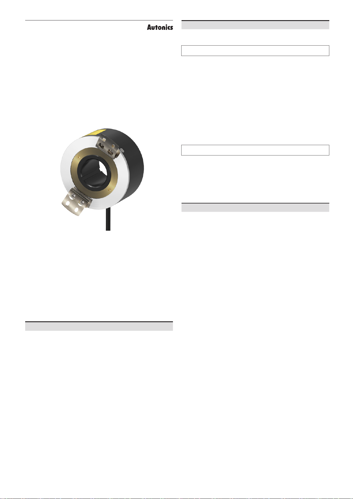
manuals.online logo
Brands
  1. Home
  2. •
  3. Brands
  4. •
  5. Autonics
  6. •
  7. Media Converter
  8. •
  9. Autonics E80 Series User manual

Autonics E80 Series User manual

-|Transparent Guide|-
TCD210026AB
80 mm Diameter
Incremental Rotary Encoders
E80 Series
PRODUCT MANUAL
For your safety, read and follow the considerations written in the instruction
manual, other manuals and Autonics website.
The speci󹃗cations, dimensions, etc. are subject to change without notice for product
improvement. Some models may be discontinued without notice.
ᜢ ᜽ ᜫ
Features
• Ø 80 mm housing, Ø 30 mm / Ø 32 mm hollow shaft
• Install directly on motors or rotating shaft. Couplings not required.
• Various resolutions: up to 3200 pulses per revolution
• Various control output options
• Power supply: 5 VDCᜡ ± 5%, 12 - 24 VDCᜡ ± 5%
Safety Considerations
• Observe all ‘Safety Considerations’ for safe and proper operation to avoid hazards.
• ᜸ symbol indicates caution due to special circumstances in which hazards may occur.
᜸ Warning Failure to follow instructions may result in serious injury or death.
01. Fail-safe device must be installed when using the unit with machinery that
may cause serious injury or substantial economic loss. (e.g. nuclear power
control, medical equipment, ships, vehicles, railways, aircraft, combustion
apparatus, safety equipment, crime / disaster prevention devices, etc.)
Failure to follow this instruction may result in personal injury, economic loss or 󹃗re.
02. Do not use the unit in the place where 󹃙ammable / explosive / corrosive gas,
high humidity, direct sunlight, radiant heat, vibration, impact or salinity
may be present.
Failure to follow this instruction may result in explosion or 󹃗re.
03. Install on a device panel to use.
Failure to follow this instruction may result in 󹃗re.
04. Do not connect, repair, or inspect the unit while connected to a power
source.
Failure to follow this instruction may result in 󹃗re.
05. Check ‘Connections’ before wiring.
Failure to follow this instruction may result in 󹃗re.
06. Do not disassemble or modify the unit.
Failure to follow this instruction may result in 󹃗re.
᜸ Caution Failure to follow instructions may result in injury or product damage.
01. Use the unit within the rated speci󹃘cations.
Failure to follow this instruction may result in 󹃗re or product damage.
02. Do not short the load.
Failure to follow this instruction may result in 󹃗re.
03. Do not use the unit near the place where there is the equipment which
generates strong magnetic force or high frequency noise and strong
alkaline, strong acidic exists.
Failure to follow this instruction may result in product damage.
Cautions during Use
• Follow instructions in ‘Cautions during Use’.
Otherwise, It may cause unexpected accidents.
• 5 VDCᜡ, 12 - 24 VDCᜡ power supply should be insulated and limited voltage / current
or Class 2, SELV power supply device.
• For using the unit with the equipment which generates noise (switching regulator,
inverter, servo motor, etc.), ground the shield wire to the F.G. terminal.
• Ground the shield wire to the F.G. terminal.
• When supplying power with SMPS, ground the F.G. terminal and connect the noise
canceling capacitor between the 0 V and F.G. terminals.
• Wire as short as possible and keep away from high voltage lines or power lines, to
prevent inductive noise.
• For Line driver unit, use the twisted pair wire which is attached seal and use the
receiver for RS-422A communication.
• Check the wire type and response frequency when extending wire because of
distortion of waveform or residual voltage increment etc. by line resistance or capacity
between lines.
• This unit may be used in the following environments.
- Indoors (in the environment condition rated in ‘Speci󹃗cations’)
- Altitude max. 2,000 m
- Pollution degree 2
- Installation category II
-|Transparent Guide|-
Product Components
• Product (+ bracket)
• Instruction manual
•󹮳 Bolt󹮳× 4
Inner Circuit
• Output circuits are identical for all output phase.
■Totem pole output ■NPN open collector output
LOAD
LOAD
CIRCUIT
Max. 10 mA
Max. 30 mA
NPN
Voltage
Max. 30 mA
CIRCUIT
LOAD
■Voltage output ■Line driver output
Max. 10 mA
CIRCUIT
LOAD
CIRCUIT
A
A
Connections
• Unused wires must be insulated.
• The metal case and shield cable of encoders must be grounded (F.G.).
• F.G. (Frame Ground) must be grounded separately.
■ Totem pole / NPN open collector / Voltage output
Pin Color Function Pin Color Function
1Black OUT A 4Brown +V
2White OUT B 5Blue GND
3Orange OUT Z 6Shield F.G.
◍ M17 6-pin layout
2
4
36
1
5
2
4
36
1
5
■Line driver output
Pin Color Function Pin Color Function
1Black OUT A 5White OUT B
2Red OUT A 6 Gray OUT B
3Brown +V 7Orange OUT Z
4Blue GND 8Yellow OUT Z
-
9Shield F.G.
◍ M17 9-pin layout
12
3
7 8 9
4 5 6
12
3
7 8 9
4 5 6
Sold Separately
• M17 connector cable: CID6S-□, CID9S-□
Cautions during Installation
• Install the unit correctly with the usage environment, location, and the designated
speci󹃗cations.
• When 󹃗xing the product with a wrench, tighten under 0.15 N m.
• Do not apply tensile strength over 30 N to the cable.
Ordering Information
This is only for reference, the actual product does not support all combinations.
For selecting the speci󹃗ed model, follow the Autonics website.
E80 ❶ ❷ -❸-❹-❺-❻-❼
❶ Shaft type
H: Hollow type
❺ Control output
T: Totem pole output
N: NPN open collector output
V: Voltage output
L: Line driver output
❷ Shaft inner diameter
30: Ø 30 mm
32: Ø 32 mm
❸ Resolution
Number: Refer to resolution in
'Speci󹃗cations'
❻ Power supply
5: 5 VDCᜡ ±5%
24: 12 - 24 VDCᜡ ±5%
❹ Output phase
3: A, B, Z
6: A, A, B, B, Z, Z
❼ Connection
No mark: Radial cable type
C: Radial cable connector type
Output Waveform
• The rotation direction is based on facing the shaft, and it is clockwise (CW) when
rotating to the right.
• Phase di󹃖erence between A and B: T
4±T
8 (T = 1 cycle of A)
■ Totem pole /
NPN open collector /
Voltage output
■Line driver output
T± T
2
H
L
T
A
H
L
Z
clockwise (CW)
H
L
B
T
4±T
8
T
2±T
4
H
L
H
L
H
L
H
L
H
L
H
L
T
A
B
Z
A
B
Z
clockwise (CW)
T
2±T
4
T
4±T
8
T± T
2
Model E80H□-□-
3-T-□-□
E80H□-□-
3-N-□-□
E80H□-□-
3-V-□-□
E80H□-□-
6-L-5-□
Power supply 5 VDCᜡ ± 5% (ripple P-P: ≤ 5%) /
12 - 24 VDCᜡ ± 5% (ripple P-P: ≤ 5%) model
Current
consumption
Totempole, NPN open collector, Voltage output: ≤ 80 mA (no load)
Line driver output: ≤ 50 mA (no load)
Insulation resistance
≥ 100 MΩ (500 VDCᜡ megger)
Dielectric strength Between the charging part and the case: 750 VACᜠ 50 / 60 Hz for 1 min
Vibration 1 mm double amplitude at frequency 10 to 55 Hz in each X, Y, Z direction
for 2 hours
Shock ≲ 75 G
Ambient temp. -10 to 70 ℃, storage: -25 to 85 ℃ (no freezing or condensation)
Ambient humi. 35 to 85%RH, storage: 35 to 90%RH (no freezing or condensation)
Protection rating IP50 (IEC standard)
Connection Radial cable type / cable connector type model
Cable spec. Ø 5 mm, 5-wire (Line driver output: 8-wire), shield cable
cable type: 2 m, cable connector type: 250 mm
Wire spec. AWG24 (0.08 mm, 40-core), insulator diameter: Ø 1 mm
Connector spec. Totempole, NPN open collector, Voltage output: M17 6-pin plug type
Line driver output: M17 9-pin plug type
Speci󹃘cations
Model E80H□-□-
3-T-□-□
E80H□-□-
3-N-□-□
E80H□-□-
3-V-□-□
E80H□-□-
6-L-5-□
Resolution 60 / 100 / 360 / 500 / 512 / 1,024 / 3,200 PPR model
Control output Totem pole
output
NPN open
collector output Voltage output Line driver
output
Output phase A, B, Z A, B, Z A, B, Z A, A, B, B, Z, Z
In󹃘ow current ≤ 30 mA ≤ 30 mA -≤ 20 mA
Residual voltage ≤ 0.4 VDCᜡ ≤ 0.4 VDCᜡ ≤ 0.4 VDCᜡ ≤ 0.5 VDCᜡ
Out󹃘ow current ≤ 10 mA - ≤ 10 mA ≤ -20 mA
Output voltage
(5 VDCᜡ)
≥ (power supply
-2.0) VDCᜡ --≥ 2.5 VDCᜡ
Output voltage
(12 - 24 VDCᜡ)
≥ (power supply
-3.0) VDCᜡ --≥ (power supply
-3.0) VDCᜡ
Response speed
01)
≤ 1 ㎲≤ 0.5 ㎲
Max. response freq.
200 kHz
Max. allowable
revolution 02) 3,600 rpm
Starting torque ≤ 0.02 N m
Inertia moment ≤ 800 g·cm2 (8 × 10⁻⁵ kg·m2)
Allowable shaft load
Radial: ≤ 5 kgf, Thrust: ≤ 2.5 kgf
Unit weight ≈ 560 g
Approval ᜢ ᜽ ᜫ ᜢ ᜽ ᜫ ᜢ ᜽ ᜫ ᜫ
01) Based on cable length: 2 m, I sink: 20 mA
02)  Select resolution to satisfy Max. allowable revolution ≥ Max. response revolution
[max. response revolution (rpm) = max. response frequency
resolution × 60 sec]
-|
Transparent Guide|-
Dimensions
•
•
6
C
A
Ø 80
B
6
A B C
10
■Bracket
12
7
22
12
7
Appearance Power
supply Connector 1Connector 2 Length Model
DC
Sold Separately: M17 Connector Cable
•
Appearance Power
supply Connector 1Connector 2 Length Model
DC

Other Autonics Media Converter manuals

Autonics E58 Series User manual

Autonics

Autonics E58 Series User manual

Autonics E60 Series User manual

Autonics

Autonics E60 Series User manual

Autonics CN-6000 Series User manual

Autonics

Autonics CN-6000 Series User manual

Autonics ENA Series User manual

Autonics

Autonics ENA Series User manual

Autonics E30 Series User manual

Autonics

Autonics E30 Series User manual

Autonics SCM-US48I User manual

Autonics

Autonics SCM-US48I User manual

Autonics E100 Series User manual

Autonics

Autonics E100 Series User manual

Autonics BFC Series User manual

Autonics

Autonics BFC Series User manual

Autonics SCM Series User manual

Autonics

Autonics SCM Series User manual

Autonics ENC Series User manual

Autonics

Autonics ENC Series User manual

Autonics E20 Series User manual

Autonics

Autonics E20 Series User manual

Autonics E40 Series User manual

Autonics

Autonics E40 Series User manual

Autonics E58 Series User manual

Autonics

Autonics E58 Series User manual

Autonics EP50 Series User manual

Autonics

Autonics EP50 Series User manual

Autonics EPM50 Series User manual

Autonics

Autonics EPM50 Series User manual

Autonics SCM Series User manual

Autonics

Autonics SCM Series User manual

Autonics BD-C Series User manual

Autonics

Autonics BD-C Series User manual

Autonics E50 Series User manual

Autonics

Autonics E50 Series User manual

Autonics E18 Series User manual

Autonics

Autonics E18 Series User manual

Autonics E58-A Series User manual

Autonics

Autonics E58-A Series User manual

Autonics SCM-WF48 User manual

Autonics

Autonics SCM-WF48 User manual

Autonics E40 Series User manual

Autonics

Autonics E40 Series User manual

Autonics SCM-WF48 User manual

Autonics

Autonics SCM-WF48 User manual

Popular Media Converter manuals by other brands

VADDIO EasyUSB AudioBRIDGE Installation and user guide

VADDIO

VADDIO EasyUSB AudioBRIDGE Installation and user guide

CONNECTRIC ENCODER-LAB02 user manual

CONNECTRIC

CONNECTRIC ENCODER-LAB02 user manual

Quark-Elec QK-A036 manual

Quark-Elec

Quark-Elec QK-A036 manual

Channel Vision A0302 instructions

Channel Vision

Channel Vision A0302 instructions

Lindy 43287 user manual

Lindy

Lindy 43287 user manual

Lika IQ58 manual

Lika

Lika IQ58 manual

LH Technologies LH 500 Operator's manual

LH Technologies

LH Technologies LH 500 Operator's manual

Xinje VH6 Series user manual

Xinje

Xinje VH6 Series user manual

Danfoss EC-C1200-450 user guide

Danfoss

Danfoss EC-C1200-450 user guide

HEIDENHAIN LIDA 475 Mounting instructions

HEIDENHAIN

HEIDENHAIN LIDA 475 Mounting instructions

RME Audio ADI-8 DS user guide

RME Audio

RME Audio ADI-8 DS user guide

Gefen GTB-UHD600-18S-RT user manual

Gefen

Gefen GTB-UHD600-18S-RT user manual

AJA HDP3 Installation and operation guide

AJA

AJA HDP3 Installation and operation guide

Fostex 3045 owner's manual

Fostex

Fostex 3045 owner's manual

TR-Electronic COV-65 user manual

TR-Electronic

TR-Electronic COV-65 user manual

Sima GoDVD! CT-2 user manual

Sima

Sima GoDVD! CT-2 user manual

iNels RFTM-1 manual

iNels

iNels RFTM-1 manual

IMC Networks iMcV-Giga-MediaLinX Operation manual

IMC Networks

IMC Networks iMcV-Giga-MediaLinX Operation manual

manuals.online logo
manuals.online logoBrands
  • About & Mission
  • Contact us
  • Privacy Policy
  • Terms and Conditions

Copyright 2025 Manuals.Online. All Rights Reserved.