manuals.online logo
Brands
  1. Home
  2. •
  3. Brands
  4. •
  5. Danfoss
  6. •
  7. Controllers
  8. •
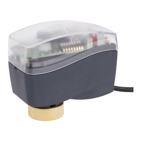
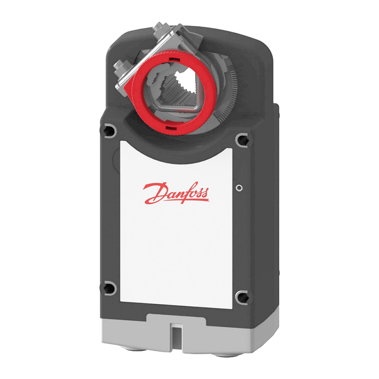
  9. Danfoss AMV 110 NL User manual

Danfoss AMV 110 NL User manual

1
Installation Guide
AMV 110 NL, AMV 120 NL
ENGLISH Actuators for three point control AMV 110 NL, AMV 120 NL www.danfoss.com Page 3
DANSK Motorer til 3-punkts styring AMV 110 NL, AMV 120 NL www.danfoss.dk Side3
DEUTSCH Die Stellantriebe AMV 110 NL und AMV 120 NL (für die 3-Punkt-Regelung) www.danfoss.de Seite 4
ESPAÑOL Actuadores de control de tres puntos AMV 110 NL y AMV 120 NL www.danfoss.es Página 4
FRANÇAIS Moteurs pour contrôle trois points AMV 110 NL, AMV 120 NL www.danfoss.fr Page 5
POLSKI Siłowniki sterowane sygnałem 3-punktowym AMV 110 NL, AMV 120 NL www.heating.danfoss.pl Strona 5
SLOVENŠČINA Tritočkovni pogoni AMV 110 NL, AMV 120 NL www.danfoss.si Stran 6
SLOVENSKY Pohony pre trojbodovú reguláciu AMV 110 NL, AMV 120 NL www.danfoss.sk Strana 6
中文 三点式控制驱动器 AMV 110 NL,AMV 120 NL www.danfoss.com 第 7 页
Heating Solutions VI.CV.C3.1E SMT/SI
AMV 110 NL, AMV 120 NL +
AB-QM (1.st gen.)
AMV 110 NL, AMV 120 NL +
AB-QM (2.nd gen.)
2
①
③
⑤
AMV 110 NL, AMV 120 NL +
AB-QM (1.st gen.)
⑤
AMV 110 NL, AMV 120 NL +
AB-QM (2.nd gen.)
 
④
②
①
②①
①
②
Installation Guide AMV 110 NL, AMV 120 NL
SMT/SI VI.CV.C3.1E Heating Solutions
❶
❷
❸
❹
33
Installation Guide AMV 110 NL, AMV 120 NL
Heating Solutions VI.CV.C3.1E SMT/SI
ENGLISH
Safety Note
Prior to assembly and commissioning to
avoid injury of persons and damages of the
devices, it is absolutely necessary to carefully
read and observe these instructions.
Necessary assembly, start-up, and
maintenance work must be performed
only by qualied, trained and authorized
personnel.
Prior to assembly and maintenance work on
the controller, the system must be:
- depressurized,
- cooled down,
- emptied and
- cleaned.
Please comply with the instructions of the
system manufacturer or system operator.
Mounting ❶
The actuator should be mounted with the
valve stem in either horizontal position or
pointing upwards. The actuator is xed to
the valve body by means of a ribbed nut
which requires no tools for mounting. The
ribbed nut should be tightened by hand.
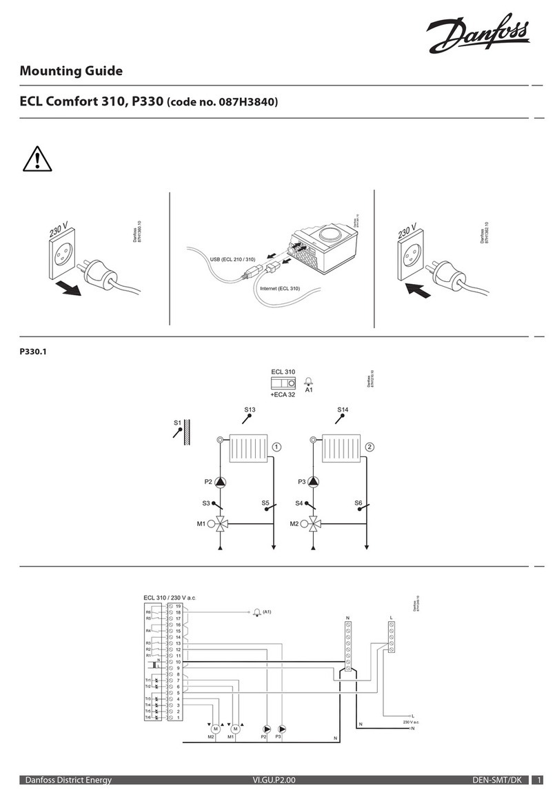
Wiring ❷
Do not touch anything on the PCB.
Installation ❸
1. Check the valve’s neck. The actuator
should be in stem up position (factory
setting). Ensure that the actuator is
mounted securely on the valve body.
2. Energize the actuator according to the
wiring diagram.
3 The direction of stem movement can be
observed on the position indicator ❸①.
Manual override ❹
(for service purposes only)
Caution:
Do not manually operate the drive under
power!
Procedure:
• Remove the cover ①.
• Press and hold the button ② (on the
bottom side of the actuator) during
manual override ③.
• Place cover back on the actuator ④.
• Install actuator on valve ⑤.
Remark:
A click after energizing the actuator indicates
that the gear wheel has jumped into normal
position.
Don’t dismount the actuator from the valve
when it is in a stem down position!
If dismounted in a stem down position, there is
a high risk that the actuator gets stuck.
DANSK
Sikkerhedsbestemmelser
Disse instruktioner skal læses omhyggeligt
forud for montering og indkøring samt
respekteres for at undgå skader på personer
og udstyr.
Nødvendigt monterings-, opstarts- og
vedligeholdelsesarbejde må kun udføres
af faglært og autoriseret personale.
Forud for monterings- og
vedligeholdelsesarbejde på regulatoren skal
systemet være:
- trykløst
- nedkølet
- tømt
- rengjort
Systemproducentens eller -operatørens
instruktioner skal overholdes.
Montering ❶
Motoren skal monteres, så ventilspindelen
enten er i vandret stilling eller peger opad.
Motoren monteres på ventilhuset med en
riet møtrik, der kan monteres uden værktøj.
Den riede møtrik skal spændes med
håndkraft.
Eltilslutning ❷
Rør ikke ved noget som helst på
printkortet!
* Grå (Grey) / Spindel ned (Stem down)
** Sort (Black) / Fælles (Common)
*** Rød (Red) / Spindel op (Stem up)
Installation ❸
1. Kontroller ventilens hals. Motoren skal stå
i en position med spindelen trukket op
(fabriksindstilling). Kontroller, at motoren
er monteret solidt på ventilhuset.
Det er obligatorisk at sætte motorens
spindel i øverste position, inden den
installeres på AB-QM-ventilen (se
tegningerne for manuel overstyring).
2. Tilslut motoren iht ledningsdiagrammet.
3. Spindelens bevægelsesretning kan ses på
positionsindikatoren ❸①.
Manuel overstyring ❹
(kun i forbindelse med service)
Forsigtig
Drevet må ikke betjenes manuelt, når
strømmen er tilsluttet!
Procedure:
• Tag dækslet af. ①
• Tryk på knappen ② (på undersiden af
motoren), og hold den inde under den
manuelle overstyring. ③
• Sæt dækslet på igen. ④
• Monter motoren på ventilen. ⑤
Bemærk:
Hvis der høres et klik, efter at strømforsyningen
er sluttet til motoren, betyder det, at tandhjulet
er drejet i normal position.
Motoren må ikke afmonteres ventilen, når
spindelen står i nederste position!
Hvis motoren afmonteres, når spindelen står
i nederste position, er der stor risiko for, at
motoren sidder fast.
4
Installation Guide AMV 110 NL, AMV 120 NL
SMT/SI VI.CV.C3.1E Heating Solutions
DEUTSCH
Sicherheitshinweise
Um Sach- und Personenschäden zu
vermeiden, ist es zwingend erforderlich,
diese Hinweise vor dem Zusammenbau und
der Inbetriebnahme aufmerksam zu lesen
und zu beachten.
Montage, Inbetriebnahme und
Wartungsarbeiten dürfen nur von
sachkundigen und autorisierten Personen
durchgeführt werden.
Vor Montage und Wartungsarbeiten am
Regler die Anlage
- drucklos machen
- abkühlen lassen
- entleeren
- reinigen
Die Vorgaben des Anlagenherstellers und
Anlagenbetreibers sind zu beachten.
Montage ❶
Der Einbau mit nach unten hängendem
Stellantrieb ist nicht zulässig! Der Stellantrieb
wird am Ventilgehäuse mittels einer
Rändelschraube befestigt, für die kein
besonderes Werkzeug nötig ist. Diese
Schraube wird mit der Hand angezogen.
Verdrahtung ❷
Bitte die Platine nicht direkt berühren!
* Grau (Grey) /
Antriebsstange ausgefahren (Stem
down)
** Schwarz (Black) / Nullleiter (Common)
*** Rot (Red) /
Antriebsstange eingefahren (Stem up)
Einbau ❸
1.
Überprüfen Sie den Anschluss am Ventil.
Die Antriebsstange des Stellantriebs sollte
eingefahren sein. Stellen Sie sicher, dass
der Stellantrieb fest auf dem Ventilkörper
montiert ist.
Die Antriebsstange der Spindel
des Stellantriebs MUSS in die
obere Position gefahren werden, bevor
der Stellantrieb auf dem
AB-QM-Durchussregler montiert
wird (Näheres entnehmen Sie
den Zeichnungen zur manuellen
Hubverstellung).
2. Verdrahten Sie den Stellantrieb gemäß dem
Verdrahtungsplan.
3. Die Bewegungsrichtung der Antriebsstange
kann an der Positionsanzeige überprüft
werden ❸①.
Manuelle Hubverstellung ❹
(nur zu Wartungszwecken)
Vorsicht:
Verstellen Sie den Antrieb nicht von Hand,
solange er unter Strom steht!
Vorgehensweise:
• Abdeckung entfernen ①
• Knopf (auf der Unterseite des Stellantriebs)
drücken ② und während der manuellen
Hubverstellung gedrückt halten③
• Abdeckung wieder aufsetzen ④
• Stellantrieb auf dem Ventil montieren ⑤
Anmerkung:
Das hörbare „Klicken“ nach dem Einschalten
der Stromzufuhr bedeutet, dass das Getriebe
in Normalstellung eingerastet ist.
Demontieren Sie den Stellantrieb nicht,
wenn die Antriebsstange voll ausgefahren
ist!
Bei einer Demontage mit voll ausgefahrener
Antriebsstange besteht die große Gefahr, dass
der Stellantrieb stecken bleibt.
Nota de seguridad
A n de evitar lesiones y daños a personas
y dispositivos, es absolutamente
imprescindible la lectura y puesta en
práctica de estas instrucciones antes de las
operaciones de montaje y puesta en servicio.
Las operaciones necesarias de montaje,
puesta en marcha y mantenimiento deberán
ser realizadas únicamente por personal
cualicado y autorizado.
Antes de llevar a cabo las operaciones de
montaje y mantenimiento del controlador, el
sistema debe ser:
- despresurizado
- enfriado
- vaciado
- limpiado
Por favor, respete las instrucciones del
fabricante u operador del sistema.
Montaje ❶
El actuador debe montarse con el vástago de
la válvula en posición horizontal u orientado
hacia arriba. El actuador se acopla al cuerpo
de la válvula por medio de una tuerca
estriada que no requiere herramientas
para su montaje. La tuerca estriada debe
apretarse con la mano.
Cableado ❷
No toque nada en la placa de circuito
impreso.
* Gris (Grey) /
Vástago hacia abajo (Stem down)
** Negro (Black) / Común (Common)
*** Rojo (Red) /
Vástago hacia arriba (Stem up)
Instalación ❸
1. Compruebe el cuello de la válvula. El
actuador deberá encontrarse con el
vástago orientado hacia arriba (ajuste de
fábrica). Asegúrese de que el actuador
queda acoplado rmemente al cuerpo de
la válvula.
Es obligatorio dirigir el eje del
actuador hacia la posición superior
antes de instalarlo en la válvula AB-QM
(consulte los esquemas de cancelación
manual).
2. Conecte el actuador de acuerdo con el
esquema de cableado.
3. La dirección de movimiento del vástago
se puede observar en el indicador de
posición ❸①.
Cancelación manual ❹
(destinada exclusivamente
a nes de mantenimiento)
Precaución:
¡No accione manualmente el actuador
si se encuentra conectado al suministro
eléctrico!
Procedimiento:
• Retire la cubierta ①
• Mantenga pulsado el botón ②
(situado en la base del actuador) durante
la cancelación manual ③
• Vuelva a colocar la cubierta ④
• Instale el actuador en la válvula ⑤
Observación:
Si el actuador emite un “clic” tras encenderlo,
ello conrma que el engranaje ha saltado a la
posición normal.
¡No desmonte el actuador de la válvula si
el vástago se encuentra orientado hacia
abajo!
Si se desmonta con el vástago orientado hacia
abajo, existe un alto riesgo de que el actuador
se obstruya.
ESPAÑOL
55
Installation Guide AMV 110 NL, AMV 120 NL
Heating Solutions VI.CV.C3.1E SMT/SI
FRANÇAIS
Sécurité
Pour éviter des dommages physiques et
matériels, il est absolument nécessaire
de lire attentivement et de respecter ces
instructions avant le montage et la mise en
service.
Le travail d’assemblage, de démarrage et de
maintenance nécessaire doit être eectué
uniquement par un personnel qualié, formé
et autorisé.
Avant le travail d'assemblage et de
maintenance du contrôleur, le système doit
être :
- dépressurisé
- refroidi
- vidé
- nettoyé
Suivre les instructions du fabricant du
système ou de son service.
Montage ❶
Le moteur doit être monté en plaçant la
tige de la vanne en position horizontale ou
orientée vers le haut. Le moteur est xé sur
le corps de la vanne par le biais d'un écrou
crenelé, qui ne nécessite aucun outil pour le
montage. L'écrou crenelé doit être serré à la
main.
Branchement éléctrique ❷
Ne touchez à rien sur la carte de circuit
imprimé.
* Gris (Grey) /
Tige en position basse (Stem down)
** Noir (Black) / Commun (Common)
*** Rouge (Red) /
Tige en position haute (Stem up)
Montage ❸
1. Vériez le col de la vanne. La tige du
moteur doit être en position haute
(réglage en usine). Assurez-vous que le
moteur est correctement xé sur le corps
de la vanne.
Il est obligatoire de mettre la broche
du moteur en position haute avant de
l'installer sur la vanne AB-QM (veuillez
consulter les dessins de débrayage
manuel).
2. Raccordez le moteur conformément au
schéma de branchement électrique.
3. Le sens du mouvement de la tige peut
être observé sur l'indicateur de position
❸①.
Débrayage manuel ❹
(à des ns d'entretien uniquement)
Attention:
Ne manœuvrez pas manuellement
l'entraînement lorsqu'il est sous tension!
Procédure:
• Déposez le capot ①
• Appuyez sur le bouton ② (situé sous
le moteur) et maintenez-le enfoncé
pendant le débrayage manuel ③
• Replacez le capot ④
• Installez le moteur sur la vanne ⑤
Remarque:
Un clic après la mise sous tension du moteur
indique que la roue dentée a rejoint sa position
normale.
Ne démontez pas le moteur de la vanne si
la tige est en position basse!
En cas de démontage avec la tige en position
basse, le moteur a de grands risques de rester
bloqué.
POLSKI
Warunki bezpieczeństwa
Aby nie dopuścić do obrażeń ciała oraz
uszkodzenia urządzeń należy przed
montażem i uruchomieniem urządzenia
bezwzględnie zapoznać się z niniejszymi
instrukcjami i przestrzegać zawartych w nich
zaleceń.
Czynności związane z montażem,
uruchomieniem i konserwacją mogą
być wykonywane wyłącznie przez
osoby wykwalikowane, przeszkolone
i uprawnione.
Przed przystąpieniem do montażu
i czynności konserwacyjnych regulatora
należy koniecznie:
- zrzucić ciśnienie,
- ochłodzić układ,
- opróżnić układ,
- oczyścić.
Należy stosować się do instrukcji producenta
i/lub operatora układu.
Montaż ❶
Siłownik powinien być tak zamontowany,
aby trzpień zaworu był skierowany do góry
lub poziomo. Siłownik jest przykręcany do
korpusu zaworu karbowaną nakrętką, więc
montaż nie wymaga żadnych narzędzi.
Karbowaną nakrętkę należy dokręcać
ręcznie.
Instalacja elektryczna ❷
Nie wolno niczego dotykać na płytce
drukowanej!
* Szary (Grey) / Trzpień w dół (Stem
down)
** Czarny (Black) / Wspólny (Common)
*** Czerwony (Red) /
Trzpień w górę (Stem up)
Instalacja ❸
1. Sprawdzić szyjkę zaworu. Siłownik
powinien znajdować się w pozycji
podniesionego trzpienia (nastawa
fabryczna). Upewnić się, że siłownik
jest pewnie zamontowany na korpusie
zaworu.
Przed zamontowaniem siłownika na
zaworze AB-QM należy obowiązkowo
wcisnąć trzpień siłownika do górnego
położenia (należy zapoznać się
z rysunkami dotyczącymi sterowania
ręcznego).
2. Podłączyć siłownik zgodnie ze
schematem połączeń elektrycznych.
3. Kierunek ruchu trzpienia można
obserwować na wskaźniku położenia
❸①.
Sterowanie ręczne ❹
(tylko w celach serwisowych)
Uwaga:
Nie wolno sterować ręcznie napędem
przy podłączonym zasilaniu!
Procedura:
• Zdjąć pokrywę ①.
• Podczas sterowania ręcznego napędem
③ nacisnąć i przytrzymać przycisk ②
(umieszczony na spodzie siłownika).
• Założyć z powrotem pokrywę ④.
• Zamontować siłownik na zaworze ⑤.
Uwaga:
„Kliknięcie” po załączeniu zasilania
elektrycznego siłownika oznacza, że koło
zębate wskoczyło na normalną pozycję
roboczą.
Nie wymontowywać siłownika z zaworu,
jeśli siłownik znajduje się w pozycji
obniżonego trzpienia!
W przypadku wymontowania w pozycji
obniżonego trzpienia istnieje wysokie
niebezpieczeństwo zakleszczenia siłownika.
6
Installation Guide AMV 110 NL, AMV 120 NL
SMT/SI VI.CV.C3.1E Heating Solutions
SLOVENŠČINA
Varnostna opozorila
Izjemno pomembno je, da pred sestavo in
zagonom skrbno preberete navodila in se jih
držite. S tem se izognete poškodbam ljudi in
okvaram na opremi.
Nujna sestavna, zagonska in vzdrževalna
dela lahko izvajajo samo kvalicirani, šolani
in pooblaščeni delavci.
Pred sestavo in vzdrževalnimi deli na
regulatorju mora biti sistem:
- pod zmanjšanim tlakom
- ohlajen
- prazen
- očiščen
Upoštevajte navodila proizvajalca sistema ali
sistemskega operaterja.
Montaža ❶
Pogon mora biti montiran zventilom,
odprtim v vodoravnem položaju ali
obrnjenim navzgor. Pogon pritrdimo na
ventil s pomočjo rebraste matice, za kar ne
potrebujemo nobenega orodja. Rebrasto
matico ročno zategnemo.
Ožičenje ❷
Ne dotikajte se ničesar na tiskanem vezju.
* Sivo (Grey) / Zapiranje (Stem down)
** Črno (Black) / Ničla (Common)
*** Rdeče (Red) / Odpiranje (Stem up)
Vgradnja ❸
1. Preverite vrat ventila. Drog pogona
mora biti uvlečen (tovarniška nastavitev).
Preverite, ali je pogon varno nameščen na
ventil.
Drog pogona mora biti pred montažo
na AB-QM ventil uvlečen (glej načrte
za ročno posredovanje).
2. Ožičite pogon v skladu značrtom
ožičenja.
3. Smer gibanja droga je prikazana na
indikatorju položaja ❸①.
Ročno posredovanje ❹
(samo za potrebe servisiranja)
Pozor:
Ne uporabljajte ročnega posredovanja, če
je pogon priključen na električno omrežje!
Postopek:
• Odstranite pokrov ①
• Med ročnim posredovanjem pritisnite in
držite gumb ② na spodnji strani pogona
③.
• Odstranite pokrov ④.
• Namestite pogon na ventil ⑤.
Opomba:
Slišen klik po priklopu na napajanje pogona
pomeni, da je zobnik preskočil v svoj običajen
položaj.
Pogona ne demontirajte zventila, ko
je drog v iztegnjenem položaju!
Če demontažo opravite z drogom v
iztegnjenem položaju, se lahko pogon zatakne.
SLOVENSKY
Bezpečnostná poznámka
Aby ste predchádzali poraneniu
apoškodeniu osôb azariadení, určite
si ešte pred montážou auvedením do
prevádzky pozorne prečítajte tieto pokyny
adodržiavajte ich.
Potrebnú montáž, spustenie aúdržbu musí
vykonávať iba kompetentný, zaškolený
aautorizovaný personál.
Pred montážnymi aúdržbárskymi prácami
na regulátore musí byť systém:
- odtlakovaný
- vychladnutý
- vyprázdnený
- vyčistený
Prosím, dodržiavajte pokyny výrobcu
systému asystémového operátora.
Montáž ❶
Pohon je treba pripevniť tak, aby bolo tiahlo
ventilu vo vodorovnej polohe alebo aby
smerovalo nahor. Pohon sa ktelesu ventilu
pripevňuje pomocou vrúbkovanej matice,
ktorá na svoju montáž nepotrebuje žiadne
nástroje. Vrúbkovanú maticu stačí dotiahnuť
ručne.
Pripojenie ❷
Nedotýkajte sa ničoho na doske plošných
spojov.
* Sivý (Grey) / Zasunuté (Stem down)
** Cierny (Black) / Spoločný (Common)
*** Cervený (Red) / Vysunuté (Stem up)
Inštalácia ❸
1. Skontrolujte hrdlo ventilu. Tiahlo
pohonu by malo byť vysunuté (výrobné
nastavenie). Skontrolujte, či je pohon
bezpečne pripevnený ktelesu ventilu.
Je nevyhnutné dať vreteno pohonu do
hornej pozície pred jeho inštaláciou
na ventil AB-QM (pozrite si prosím,
nákresy ručného ovládania).
2. Zapojte pohon podľa schémy pripojenia.
3. Na indikátore polohy môžete sledovať
smer pohybu tiahla ❸①.
Ručné ovládanie ❹
(iba pre servisné účely)
Upozornenie:
Ak je zariadenie pod prúdom,
nesnažte sa ho ovládať ručne!
Postup:
• Odoberte kryt ①
• Pri manuálnom ovládaní stlačte tlačidlo a
podržte ho ② (tlačidlo na spodnej strane
pohonu) ③
• Odoberte kryt ④
• Namontujte pohon na ventil ⑤
Poznámka:
Keď po spustení pohonu budete počuť
kliknutie, znamená to, že ozubené koleso
zapadlo do správnej polohy.
Ak je tiahlo zasunuté, nedemontujte pohon
zventila!
Ak je tiahlo zasunuté, je vyššia
pravdepodobnosť, že sa pohon pri
odstraňovaní zasekne.
77
Installation Guide AMV 110 NL, AMV 120 NL
Heating Solutions VI.CV.C3.1E SMT/SI
DEUTSCH
中文
安全事项
为避免人员受伤或设备受损,在安装和启用
之前,请务必认真阅读并严格遵守下列说明。
所需的安装、启动和维护工作必须由训练有
素且获得授权的合格人员进行。
在对控制器进行安装和维护之前,必须将系
统:
- 减压
- 冷却
- 清空
- 清洁
请服从系统制造商或系统操作员的指导。
安装❶
安装驱动器时,必须让阀杆处于水平位置或
指向上方。 驱动器是用一个螺帽固定在阀身
之上,安装螺帽时不需要工具。 应当用手将
螺帽拧紧。
线路连接❷
切勿触碰印刷电路板上的任何元件。
* 灰色 (Grey) / 阀杆朝下 (Stem down)
** 黑色 (Black) / 公共 (Common)
*** 红色 (Red) / 阀杆朝上 (Stem up)
安装❸
1. 检查阀门颈部。 驱动器应当位于阀杆朝
上的位置(出厂设定)。 务必将驱动器牢
牢地安装在阀身之上。
必须先将驱动器的驱动杆推到上方位
置,然后方可把它安装到 AB-QM 阀门
上(请参阅手动操作图)。
2. 按照接线图对致动器进行接线。
3. 阀杆的运动方向可以在位置指示器上观察
到 ❸①。
手动操作❹
(仅用于维修的目的)
注意:
严禁在电源接通时对驱动器进行
手动操作。
步骤:
• 取掉顶盖 ①
• 手动操作时 ③ 按住按钮不放 ② (位于
驱动器的底部)
• 盖好顶盖 ④
• 将驱动器安装到阀门上 ⑤
注意:
驱动器通电后会发出一声“咔嗒”声,这表明
齿轮已经进入正常位置。
当驱动器处于阀杆位于下端位置时,不要从
阀门上拆卸驱动器!
如果在阀杆位于下端位置时拆卸,驱动器很
可能会卡住。
Installation Guide AMV 110 NL, AMV 120 NL
73697000/VI.CV.C3.1E Produced by Danfoss A/S © 02/2012

This manual suits for next models

1

Other Danfoss Controllers manuals

Danfoss EKC 316A User manual

Danfoss

Danfoss EKC 316A User manual

Danfoss SAF VFU21 Series User manual

Danfoss

Danfoss SAF VFU21 Series User manual

Danfoss AME 55QM User manual

Danfoss

Danfoss AME 55QM User manual

Danfoss EKC 223 User manual

Danfoss

Danfoss EKC 223 User manual

Danfoss PK37 User manual

Danfoss

Danfoss PK37 User manual

Danfoss MCO 305 User manual

Danfoss

Danfoss MCO 305 User manual

Danfoss ASV-PF User manual

Danfoss

Danfoss ASV-PF User manual

Danfoss VLT Automation VT Drive FC 322 Operating instructions

Danfoss

Danfoss VLT Automation VT Drive FC 322 Operating instructions

Danfoss EKC 102C2 User manual

Danfoss

Danfoss EKC 102C2 User manual

Danfoss AK-PC 572 User manual

Danfoss

Danfoss AK-PC 572 User manual

Danfoss ADAP-KOOL AK-HP 780 Guide

Danfoss

Danfoss ADAP-KOOL AK-HP 780 Guide

Danfoss AK-CS User manual

Danfoss

Danfoss AK-CS User manual

Danfoss AME 110 NLX User manual

Danfoss

Danfoss AME 110 NLX User manual

Danfoss AMV 335 User manual

Danfoss

Danfoss AMV 335 User manual

Danfoss DEVIreg Multi User manual

Danfoss

Danfoss DEVIreg Multi User manual

Danfoss AME 438 SU User manual

Danfoss

Danfoss AME 438 SU User manual

Danfoss ERC 213 User manual

Danfoss

Danfoss ERC 213 User manual

Danfoss EKC 331T User manual

Danfoss

Danfoss EKC 331T User manual

Danfoss VLT AutomationDrive FC 302 User manual

Danfoss

Danfoss VLT AutomationDrive FC 302 User manual

Danfoss AK-CC55 User manual

Danfoss

Danfoss AK-CC55 User manual

Danfoss EKE 1A User manual

Danfoss

Danfoss EKE 1A User manual

Danfoss ISD Encoder Box User manual

Danfoss

Danfoss ISD Encoder Box User manual

Danfoss AME 855 User manual

Danfoss

Danfoss AME 855 User manual

Danfoss Optyma Plus OP-MPS User manual

Danfoss

Danfoss Optyma Plus OP-MPS User manual

Popular Controllers manuals by other brands

Lab.gruppen LAB.LEVEL4 quick start guide

Lab.gruppen

Lab.gruppen LAB.LEVEL4 quick start guide

fadini Elpro 37DS manual

fadini

fadini Elpro 37DS manual

Linear Technology DC2268A-1 Demo Manual

Linear Technology

Linear Technology DC2268A-1 Demo Manual

Johnson Controls FEC16 Series installation instructions

Johnson Controls

Johnson Controls FEC16 Series installation instructions

TMK IGNIS Alfa manual

TMK

TMK IGNIS Alfa manual

ST STM32W-SK user manual

ST

ST STM32W-SK user manual

Evco EV3143 quick start guide

Evco

Evco EV3143 quick start guide

Chauvet Professional RDM2go Quick reference guide

Chauvet Professional

Chauvet Professional RDM2go Quick reference guide

Koso REXA Electraulic Xpac Installation and operation manual

Koso

Koso REXA Electraulic Xpac Installation and operation manual

Siro 40567 instruction manual

Siro

Siro 40567 instruction manual

AG-NAV AgNav Platinum Operation manual

AG-NAV

AG-NAV AgNav Platinum Operation manual

Paxton Switch2 How to program

Paxton

Paxton Switch2 How to program

DH Instruments OPG1-30000-AF Operation and maintenance manual

DH Instruments

DH Instruments OPG1-30000-AF Operation and maintenance manual

Omnio APG03B-RS485 manual

Omnio

Omnio APG03B-RS485 manual

Netafim NMC-64 User & installation manual

Netafim

Netafim NMC-64 User & installation manual

Ko Propo BSx2 Series manual

Ko Propo

Ko Propo BSx2 Series manual

Johnson Controls FAC2611 installation guide

Johnson Controls

Johnson Controls FAC2611 installation guide

Bodyfriend LBF-R700 manual

Bodyfriend

Bodyfriend LBF-R700 manual

manuals.online logo
manuals.online logoBrands
  • About & Mission
  • Contact us
  • Privacy Policy
  • Terms and Conditions

Copyright 2025 Manuals.Online. All Rights Reserved.