Danfoss AME 110 NL User manual
Other Danfoss Controllers manuals
Danfoss
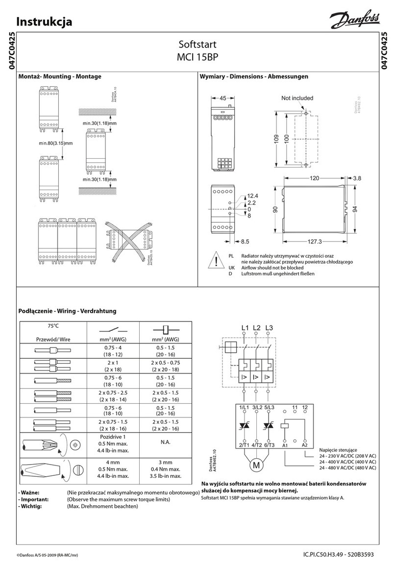
Danfoss MCI 15BP User manual
Danfoss
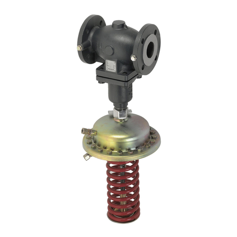
Danfoss AFD 2/VFG 2 User manual
Danfoss
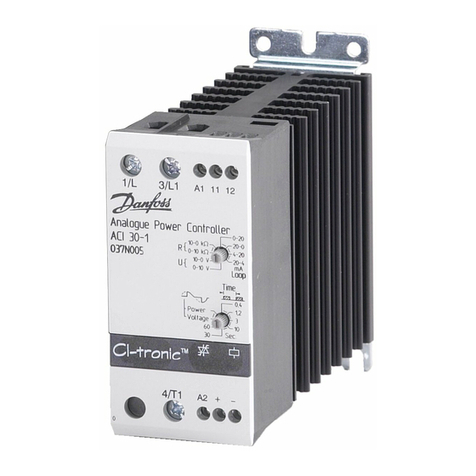
Danfoss ACI 30-1 User manual
Danfoss
Danfoss VACON 100 industrial User manual
Danfoss
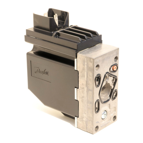
Danfoss PVE Series User manual
Danfoss
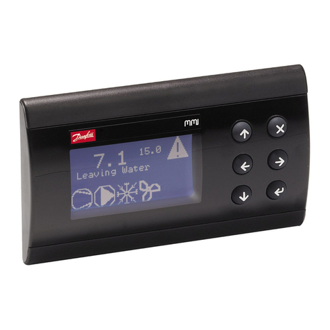
Danfoss MMIGRS2 User manual
Danfoss
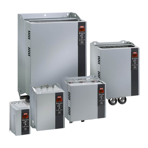
Danfoss vlt soft starter mcd 500 User manual
Danfoss
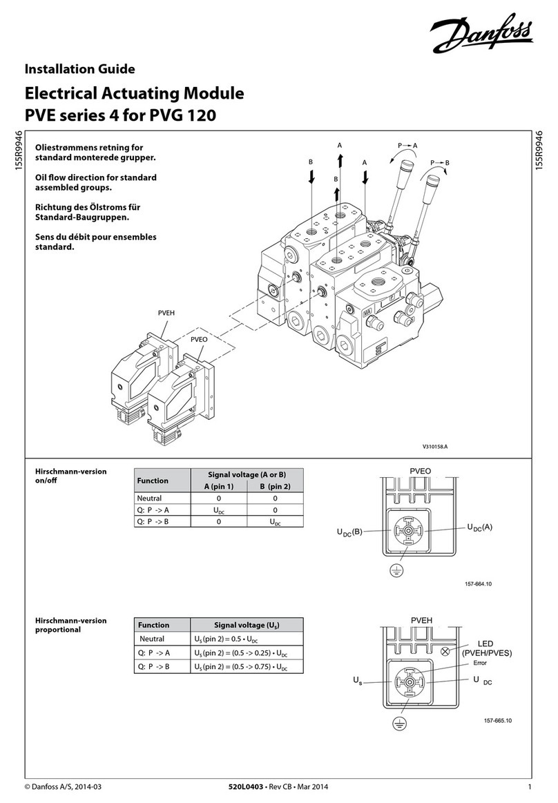
Danfoss PVE 4 Series User manual
Danfoss
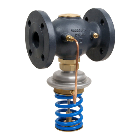
Danfoss AVA User manual
Danfoss
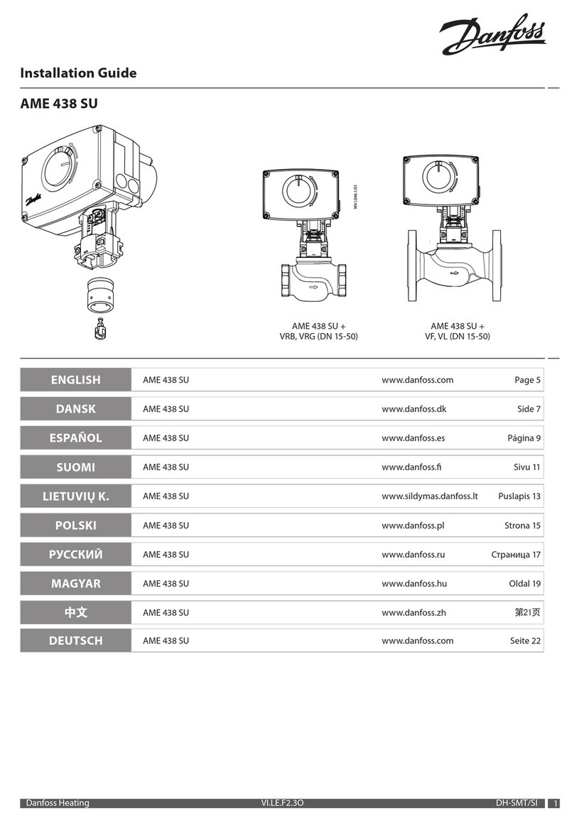
Danfoss AME 438 SU User manual
Danfoss
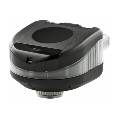
Danfoss NovoCon S 003Z8504 User manual

Danfoss
Danfoss AMV 610 User manual
Danfoss
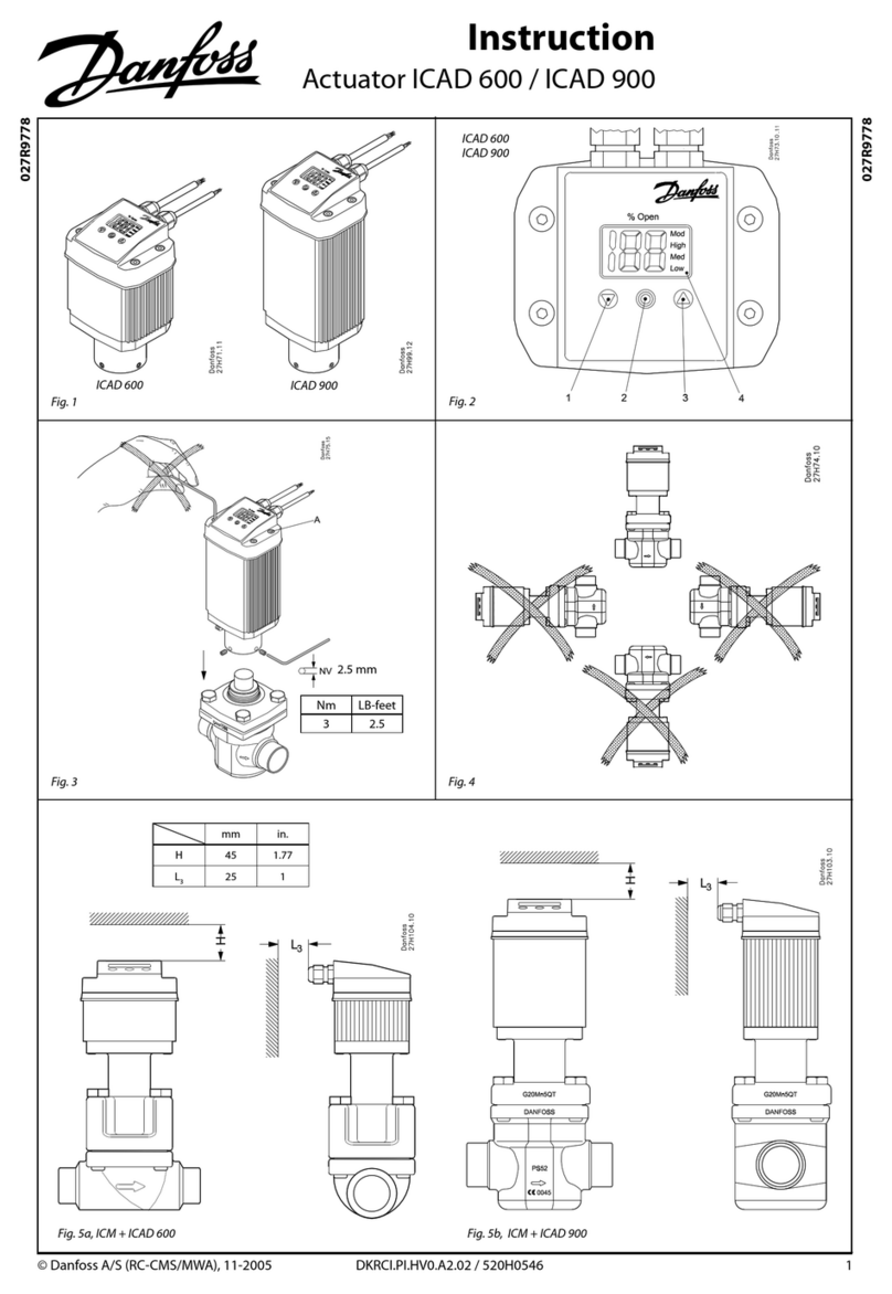
Danfoss Old ICAD 600 series User manual
Danfoss
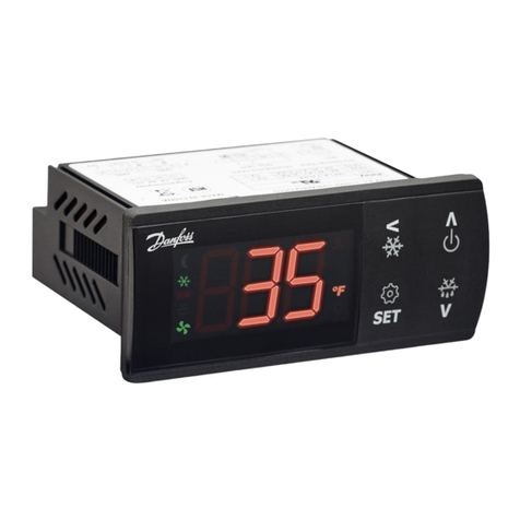
Danfoss ERC 21 Series User manual
Danfoss
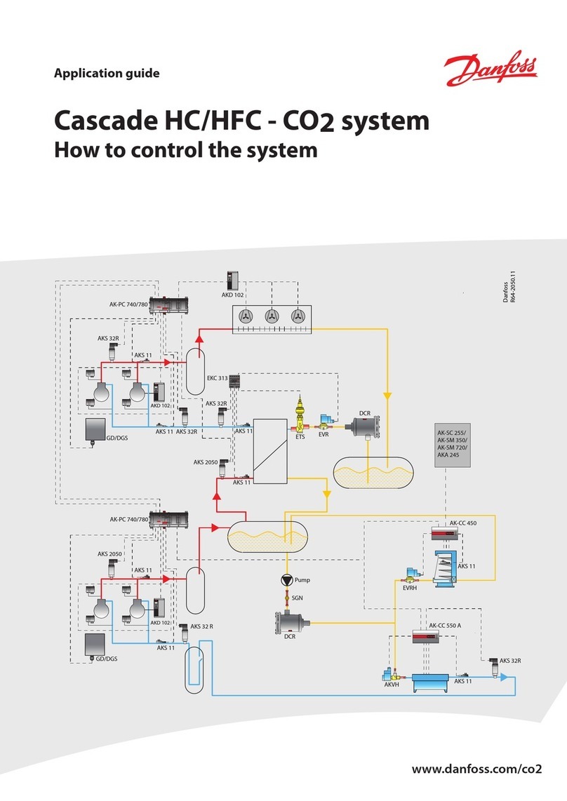
Danfoss Cascade HFC User guide
Danfoss
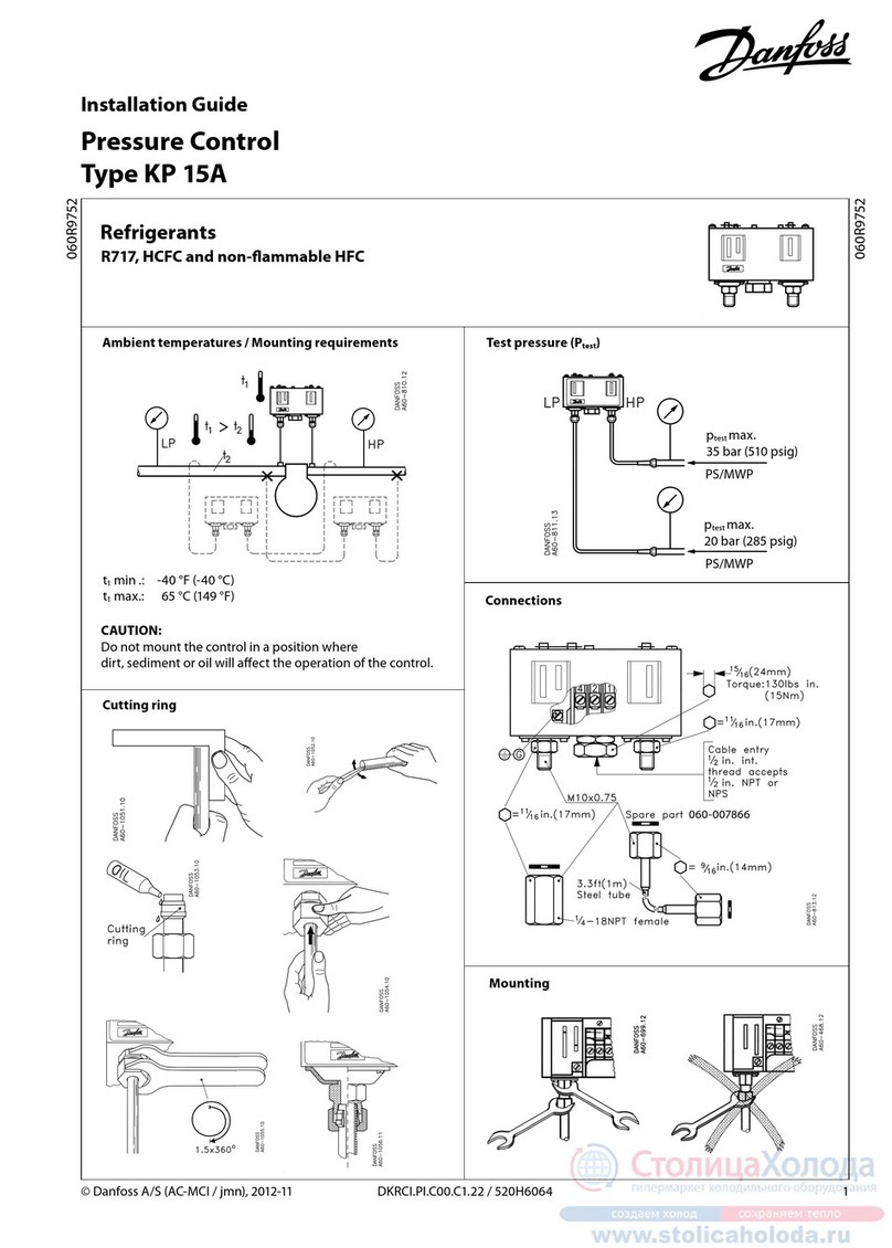
Danfoss KP 15A User manual

Danfoss
Danfoss AK-CC 750A User manual
Danfoss
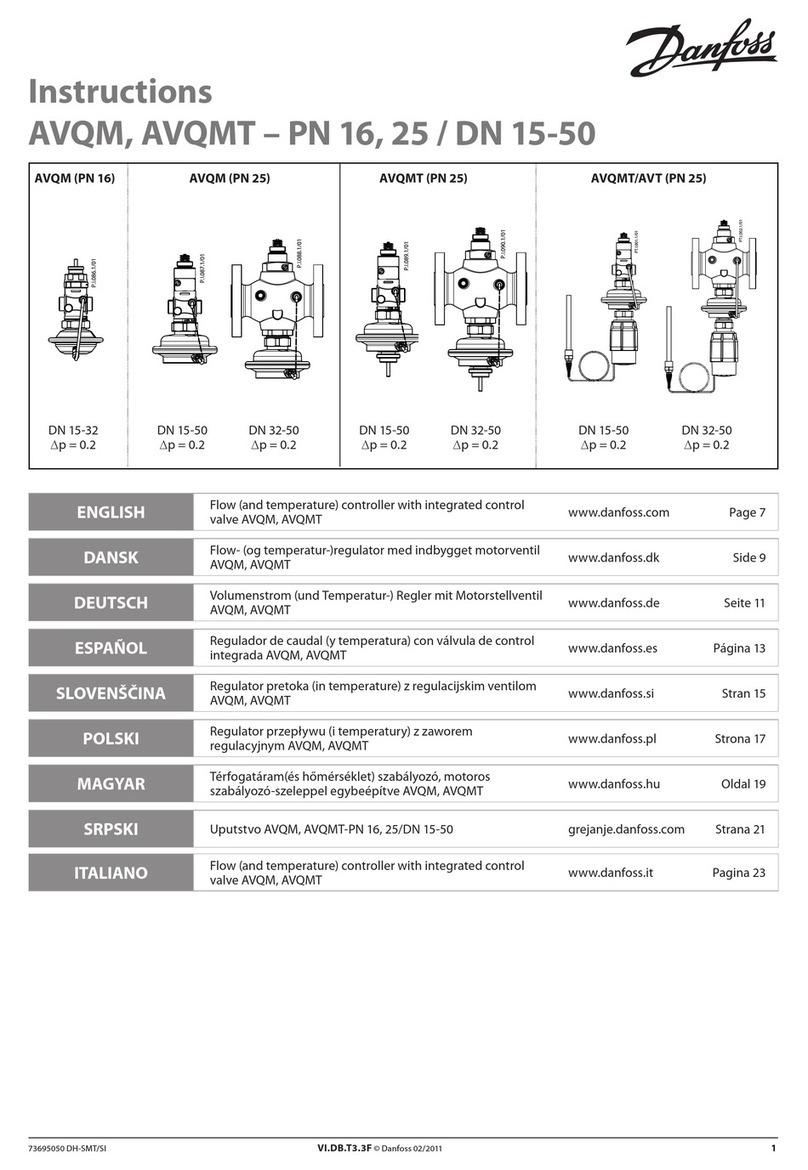
Danfoss AVQM Series User manual
Danfoss
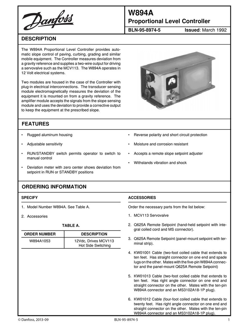
Danfoss W894A User manual
Danfoss
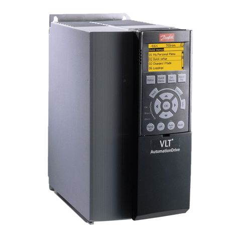
Danfoss VLT AutomationDrive FC 300 User manual
Popular Controllers manuals by other brands

Digiplex
Digiplex DGP-848 Programming guide

YASKAWA
YASKAWA SGM series user manual

Sinope
Sinope Calypso RM3500ZB installation guide

Isimet
Isimet DLA Series Style 2 Installation, Operations, Start-up and Maintenance Instructions

LSIS
LSIS sv-ip5a user manual

Airflow
Airflow Uno hab Installation and operating instructions
