manuals.online logo
Brands
  1. Home
  2. •
  3. Brands
  4. •
  5. Danfoss
  6. •
  7. Controllers
  8. •
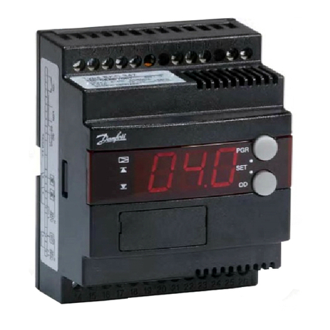
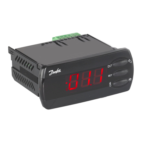
  9. Danfoss EKC 201 User manual

Danfoss EKC 201 User manual

106
RI.8A.E1.52 ➝➝
➝➝
➝ RI.8A.E2.67 11-1999
084R9697
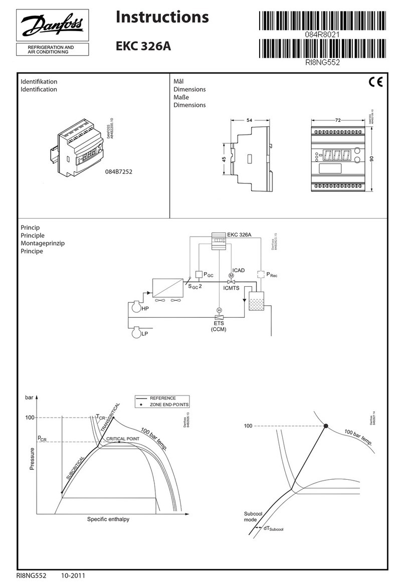
INSTRUCTIONS
EKC 201, EKC 301
EKC 201 EKC 301
tamb. = 0 - +55°C tamb. = 0 - +55°C
IP 20
Fig. 1
Fig.4
Fig. 2 Fig. 3
Fig. 7Fig. 5
Fig. 8
084R9697
12 V a.c./d.c./230 V a.c.
2.5 VA
230 V a.c.
5 VA
EKC 201, 12 V EKC 201, 230 V EKC 301
T1 / (T2)
Fig. 6
10 V < U < 256 V
Imax (AC-1) = 6 A
Imax (AC-15) = 3 A
10 V < U < 256 V
Imax (AC-1) = 4 A
Imax (AC-15) = 1 A
107
DANSK DEUTSCH
ENGLISH FRANCAIS
Elektroniske regulatorer
EKC 201: Til indbygning i tavle.
EKC 301: Til montering på DIN-
skinne.
Montering Se fig. 1-4 og fig. 8.
El-tilslutning
Se fig. 5-7 samt el-diagram på
apparatet.
12 V regulatorerne skal tilsluttes
separat transformer på min. 3 VA.
Betjening
(Se fig. 9).
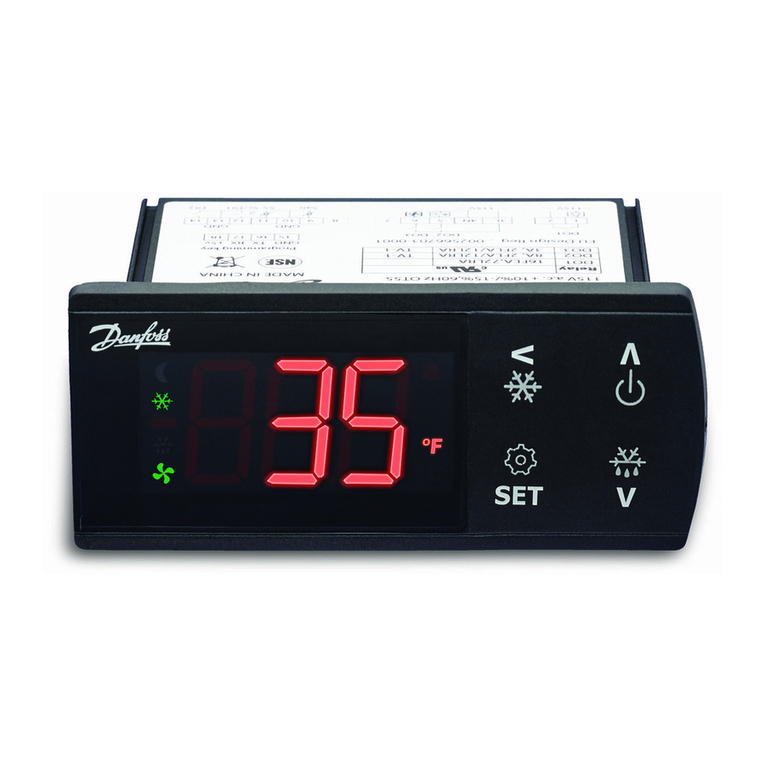
1. Lysdiode
= køling
= afrimning
= ventilator i gang
Blinker langsomt ved indstilling
Blinker hurtigt ved alarm
2. Minustegn.
3. Display.
(Blinker når indstillingsværdien
for rumtemperaturen vises).
4. Taster til programmering og
indstilling
(se programmeringsvejledning).
Programmering og indstilling
Se programmeringsvejledningen og
indstillinger.
Tryk på øverste tast i 2 s.
Tryk på nederste tast i 2 s.
Tryk på begge taster samtidigt.
Electronic controllers
EKC 201: For panel mounting
EKC 301: For DIN-rail mounting
Installation See figs. 1-4 and fig. 8.
Electrical connection
See figs 5-7 and electrical diagram
on unit.
The 12 V controllers must be con-
nected separately: transformer of
min. 3 VA.
Operation
(See fig. 9).
1. Light emitting diode
= refrigeration
= defrost
= fan running
Flashes slowly at setting
Flashes fast at alarm
2. Minus sign
3. Display
(Flashes when setting value for
room temp. is displayed).
4. Keys for programming and
setting
(see programming instructions).
Programming and setting
see programming instructions and
settings.
Press upper key for 2 s.
Press lower key for 2 s.
Press both keys at the same
time.
Elektronische Regler
EKC 201: Für den Schalt-
tafeleinbau.
EKC 301: Für die Montage auf
DIN-Schiene.
Montage Siehe Abb. 1 - 4 und
Abb. 8.
Elektrischer Anschluß
Siehe Abb. 5-7 sowie Schaltplan
am Regler.
12 V-Regler müssen an separaten
Trafo von min. 3 VA angeschlossen
werden.
Bedienung
(Siehe Abb. 9).
1. Leuchtdiode
= Kühlung
= Abtauung
= Lüfter läuft
Blinkt langsam bei Einstellung
Blinkt schnell bei Alarm
2. Minuszeichen
3. Display
(Blinkt, wenn der Einstellwert
der Raumtemperatur angezeigt
wird).
4. Tasten zur Programmierung
und Einstellung. (Siehe
Programmierungsanleitung).
Programmierung und
Einstellung
Siehe Programmierungsanleitung
und Einstellungen.
Obere Taste für 2 s betätigen.
Untere Taste für 2 s betätigen.
Beide Tasten gleichzeitig
betätigen.
Régulateurs électroniques
EKC 201 : pour montage sur tableau
EKC 301 : pour montage sur rail DIN
Montage
Voir fig. de 1 à 4 et fig. 8.
Connexion électrique
Voir fig. 5-7 ainsi que le diagramme
électrique sur l’appareil.
Les régulateurs de 12 V doivent se
brancher sur un transformateur
séparé d’au moins 3 VA.
Utilisation
(Voir fig. 9).
1. Diode lumineuse
= refroidissement
= dégivrage
= ventilateur en fonction
Clignotement lent pendant le
réglage
Clignotement rapide en cas
d‘alarme
2. Signe moins (-).
3. Affichage.
(Clignote quand la température
de réglage est atteinte).
4. Touches pour programmation et
réglage (voir instructions de
programmation).
Programmation et réglage
Consulter les instructions de
programmation et les réglages.
Presser sur la touche
supérieure pendant 2 sec.
Presser sur la touche inférieure
pendant 2 sec.
Presser sur les deux touches en
même temps.
Fig. 9
ESPAÑOL ITALIANO
Controllore elettronico
EKC 201: per montaggio su
pannello
EKC 301: per montaggio su barra
DIN
Installazione Vd. Fig. 1-4 e fig. 8.
Connessioni elettriche
Vedi fig. 5-7 e gli schemi elettrici
I regolatori 12 V devono essere
collegati ad un trasformatore
singolo da 3VA.
Funzionamento
(vd Fig. 9).
1. Led luminoso
= refrigerazione
= sbrinamento
= ventilatore
Il led lampeggia lentamente
durante l‘impostazione
parametri
Il led lampeggia velocemente
durante un allarme
2. Segno meno
3. Display
(lampeggia durante
l’impostazione temp.
ambiente).
4. Tasti per programmare e tarare
(vedi le istruzioni di
programmazione)
Programmare e tarare
Vedi le istruzioni di
programmazione
Premi il tasto superiore per
2 secondi
Premi il tasto inferiore per
2 secondi
Premi entrambi i tasti allo
stesso tempo
Controlador electrónico
EKC 201: Para montaje en panel
EKC 301: Para montaje en rail DIN
Instalación Ver fig. 1-4 y fig. 8.
Conexionado eléctrico
Ver fig. 5-7 y diagrama electrico de
la unidad.
Los controladores de 12 V se
deben conectar por separado:
transformador minimo de 3VA.
Operación
(Ver fig. 9).
1. LED Diodo luminoso
= refrigeración
= desescarche
= marcha de ventiladores
Parpadea ligeramente al
ajustarse
Parpadea rapidamente en
estado de alarma
2. Signo menos
3. Pantalla
(Parpadea cuando se realiza el
ajuste de la temperatura).
4. Botones de programación y
ajustes
(ver instrucciones de
programación).
Programación y ajustes
Ver instrucciones de programación
y ajustes.
Pulsar el boton superior durante
dos segundos
Pulsar el boton inferior durante
dos segundos
Pulsar los dos botones a la vez
108
Controller application setting parameters
Quick Guide
1) The compressor relay closes when the room temperature exceeds the setting value and differential.
2) Alarm is released and sensor failure is indicated, if the room temperature reaches 5°C or more outside the setting range
–60° to +50°C.
3) The frequency is measured after approx. three days and nights operation after start of the plant (72 cyclings) otherwise:
ON-time = c03 x 20: 100 minutes
OFF-time interval 20 minus ON-time per minute
4) Function possibilities with SPST contact, connected to the terminals 3 and 4 are the following:
Door alarm
: If SPST is cut out, alarm signalling starts and the fan is stopped, cf. A04 or F03.
Defrost:
If SPST is cut in, defrost starts.
(However, if d03 is not OFF, defrost will during contact break down start with the programmed time intervalles).
Bus
: With installed communication card, the position of the SPST contacts will be registered in the BUS system.
Operating the two pushbuttons
Display
readout
What the controller does automatically
Resulting
controller
setup
Normal
operation
Room
temp. 2
Normal
operation
(or alarm)
Known
codes
and settings
All parameter
settings
= factory
settings
Normal
operation
Normal
operation
Normal
operation
Alarm relay
not
activated
Alarm
Room
temp.
Room
temp.
Set
value
Change
ChangeChange
Set
value
Room
temp.
Room
temp.
Power off Power
on
Room
temp.
Room
temp.
Room
temp.
Room
temp.
Room
temp.
Alarm code/
Fault code
Alarm code/
Fault code
Room temp.
Room temp.
Defrost operation
Defrost sensor temp.
What
to do
Initial
controller
setup
Read
or
change
room
temp.
setting
Read
or change
parameter
codes
and
settings
Re-establish
all factory
settings
Read
defrost
sensor
temp.
Manually
start of
a defrost
operation
Manually
stop of
a defrost
operation
Reset
alarm
relay
Read codes
cause of
alarm mode
Normal
operation
Room
temp. 1
Normal
operation
(or alarm)
Unknown
codes
and settings
Unknown
settings
Normal
operation
or alarm
Normal
operation
Defrost
operation
Alarm
relay
activated
Alarm relay
not
activated
Room
temp.
Room
temp.
Code
Room
temp.
Room
temp.
Room
temp.
Room
temp.
Room
temp.
Room
temp.
Para- Controller Min. Max. Factory Actual
Setting and read-off parameters meter application no. value value setting setting
codes 1234
Temperature controller, Temperature -60
o
C50
o
C3
o
C
Thermostat
Differential
1
) r01 0.1 K 20 K 2 K
Max. limitation of set temperature r02 -59
o
C50
o
C50
o
C
Min. limitation of set temperature r03 -60
o
C49
o
C -60
o
C
Adjustment of temperature indication r04 20 K 20 K 0.0 K
Temperature unit (°C/°F) r05
o
C
Alarm
Upper deviation (above temp. setting + differential
2
) A01 0 K 50 K 10 K
Lower deviation (below temp. setting
2
) A02 50 K 0 K 10 K
Temperature alarm delay A03 0 min 90 min 30 min
Door alarm delay A04 0 min 90 min 60 min
Compressor
Min. ON-time c01 0 min 15 min 0 min
Min. OFF-time c02 0 min 15 min 0 min
Cut-in frequency on sensor fault
3
) c03 0 % 100 % 0 %
Compressor stop at open door (yes/no) c04 no
Defrost
Defrost method (EL/GAS) d01 EL
Defrost stop temperature d02 0
o
C25
o
C6
o
C
Interval between defrost starts d03 OFF 48 hour 8 hour
Max. defrost duration d04 0 min 180 min 45 min
Defrost time delay (after power up) d05 0 min 60 min 0 min
Drip-off time d06 0 min 20 min 0 min
Fan start delay after defrost d07 0 min 20 min 1 min
Fan start temperature d08 -15
o
C0
o
C-5
o
C
Fan cut-in during defrost (yes/no) d09 no
Defrost sensor (yes/no) d10 yes
Temperature alarm delay after defrost d11 0 min 199 min 90 min
Delay of display view after defrost stop d12 0 min 15 min 1 min
Fan
Fan stop on compressor cut-out (yes/no) F01 no
Fan stop delay F02 0 min 30 min 0 min
Fan stop at open door (yes/no) F03 yes
Miscellaneous
Delay of output signal after start-up o01 0 s 600 s 5 s
Digital input signals
4
)
(0 = not used, 1 = door alarm, 2 = defrost, 3 = bus) o02 0
Access code o05 OFF 100 OFF
Used sensor type (Pt / PTC) o06 Pt/PTC
Real time clock (if fitted)
Six start times for defrost
All can be cut out by setting on OFF t01→t06 0 23 OFF
Hour setting t07 0 hour 23 hour 0 hour
Minute setting t08 0 min 59 min 0 min
Fault code display Alarm code display Status code display
E 1 Fault in controller A 1 High temperature alarm S 2 ON-time
E 2 Disconnected room sensor A 2 Low temperature alarm S 3 OFF-time
E 3 Short-circuited room sensor A 4 Door alarm S 4 Drip-off time
E 4 Disconnected defrost sensor
E 5 Short-circuited defrost sensor
E 6 Change battery

This manual suits for next models

1

Other Danfoss Controllers manuals

Danfoss VLT AutomationDrive FC 300 Guide

Danfoss

Danfoss VLT AutomationDrive FC 300 Guide

Danfoss VLT 6000 series User manual

Danfoss

Danfoss VLT 6000 series User manual

Danfoss RAVK User manual

Danfoss

Danfoss RAVK User manual

Danfoss EKC 202B User manual

Danfoss

Danfoss EKC 202B User manual

Danfoss AME 85 QM User manual

Danfoss

Danfoss AME 85 QM User manual

Danfoss Cascade HFC User guide

Danfoss

Danfoss Cascade HFC User guide

Danfoss erc 112 User manual

Danfoss

Danfoss erc 112 User manual

Danfoss 324166 Owner's manual

Danfoss

Danfoss 324166 Owner's manual

Danfoss AMD 413 User manual

Danfoss

Danfoss AMD 413 User manual

Danfoss EKC 315A User manual

Danfoss

Danfoss EKC 315A User manual

Danfoss SAF VFU21 Series User manual

Danfoss

Danfoss SAF VFU21 Series User manual

Danfoss AMI 140 Series User manual

Danfoss

Danfoss AMI 140 Series User manual

Danfoss AME 56 User manual

Danfoss

Danfoss AME 56 User manual

Danfoss AMV 610 User manual

Danfoss

Danfoss AMV 610 User manual

Danfoss AK-PC 572 User manual

Danfoss

Danfoss AK-PC 572 User manual

Danfoss FP715Si User manual

Danfoss

Danfoss FP715Si User manual

Danfoss AMI 120 NL-1 User manual

Danfoss

Danfoss AMI 120 NL-1 User manual

Danfoss AK-CC55 User manual

Danfoss

Danfoss AK-CC55 User manual

Danfoss HFX Series User manual

Danfoss

Danfoss HFX Series User manual

Danfoss VLT AutomationDrive FC 302 User manual

Danfoss

Danfoss VLT AutomationDrive FC 302 User manual

Danfoss ISD Encoder Box User manual

Danfoss

Danfoss ISD Encoder Box User manual

Danfoss AME 438 SU User manual

Danfoss

Danfoss AME 438 SU User manual

Danfoss EKC 316A User manual

Danfoss

Danfoss EKC 316A User manual

Danfoss ADAP-KOOL AK-PC 551 User manual

Danfoss

Danfoss ADAP-KOOL AK-PC 551 User manual

Popular Controllers manuals by other brands

Epever MPPT user manual

Epever

Epever MPPT user manual

Dynamatic 4000 instruction sheet

Dynamatic

Dynamatic 4000 instruction sheet

Advantech B+B SmartWorx Wzzard BB-WSK-NRG-1 Setup manual

Advantech

Advantech B+B SmartWorx Wzzard BB-WSK-NRG-1 Setup manual

Planar Dome Md2/PCI Developer's guide

Planar

Planar Dome Md2/PCI Developer's guide

YSD KZ55 user manual

YSD

YSD KZ55 user manual

Festo CECX-X-C1 Series manual

Festo

Festo CECX-X-C1 Series manual

TMS Lite High Current Series user manual

TMS Lite

TMS Lite High Current Series user manual

NAVITAS TAC 1.0 Installation & service manual

NAVITAS

NAVITAS TAC 1.0 Installation & service manual

BIGSTONE C500B-LCD instructions

BIGSTONE

BIGSTONE C500B-LCD instructions

ABB RC/A 8.2 Mounting and operation instructions

ABB

ABB RC/A 8.2 Mounting and operation instructions

SMSC USB2242 datasheet

SMSC

SMSC USB2242 datasheet

Epson RC620 Series manual

Epson

Epson RC620 Series manual

GeoVision GV-AS200 quick start guide

GeoVision

GeoVision GV-AS200 quick start guide

LG MultiSITE VM3 Startup guide

LG

LG MultiSITE VM3 Startup guide

Shinko PCA1 instruction manual

Shinko

Shinko PCA1 instruction manual

ALLEN & HEATH iDR-4 Service information

ALLEN & HEATH

ALLEN & HEATH iDR-4 Service information

Novus N20K48 user guide

Novus

Novus N20K48 user guide

AMX AXB-VOL3 installation guide

AMX

AMX AXB-VOL3 installation guide

manuals.online logo
manuals.online logoBrands
  • About & Mission
  • Contact us
  • Privacy Policy
  • Terms and Conditions

Copyright 2025 Manuals.Online. All Rights Reserved.