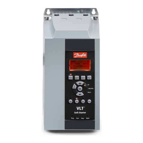
Danfoss VLT MCD 200 User manual
Other Danfoss Controllers manuals
Danfoss
Danfoss AK2-SC 255 User manual
Danfoss
Danfoss Danfoss Link User manual
Danfoss
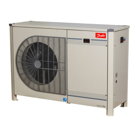
Danfoss OPTYMA Plus OP-LPQM User manual
Danfoss
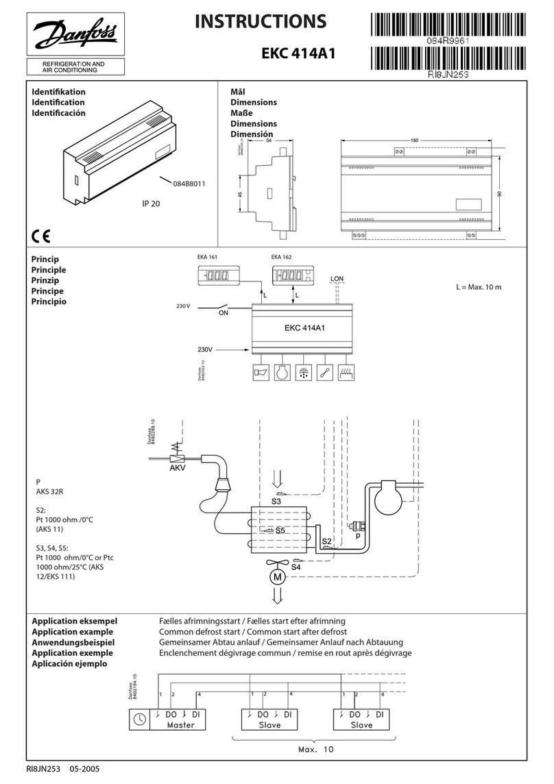
Danfoss EKC 414A1 User manual
Danfoss
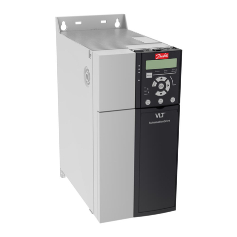
Danfoss VLT AutomationDrive FC 360 Operating instructions
Danfoss
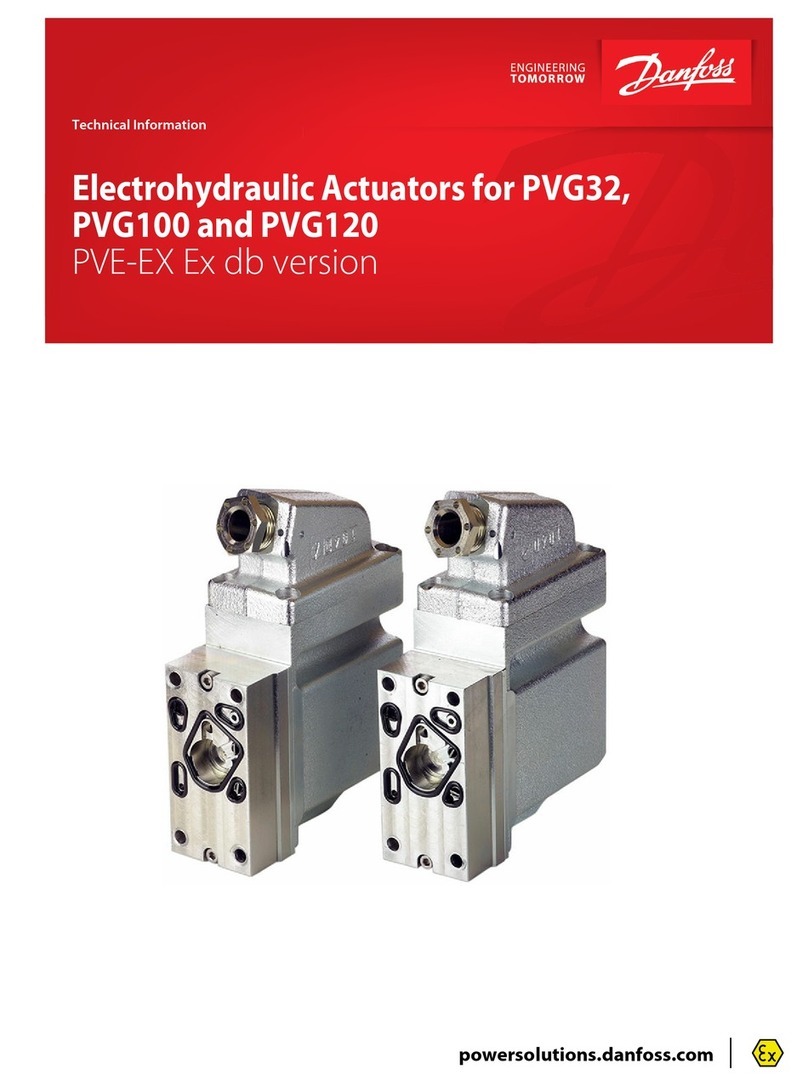
Danfoss PVE 7 Series Manual
Danfoss
Danfoss ECL Comfort 100M User manual
Danfoss
Danfoss EIM 365 User manual
Danfoss
Danfoss AMI 120 NL-1 User manual
Danfoss
Danfoss EKC 302D User manual
Danfoss
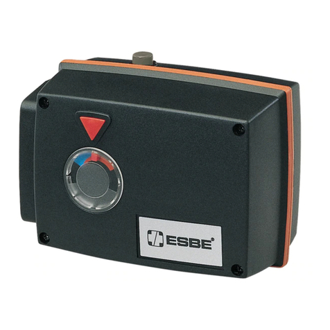
Danfoss ESBE 90 Series User manual
Danfoss
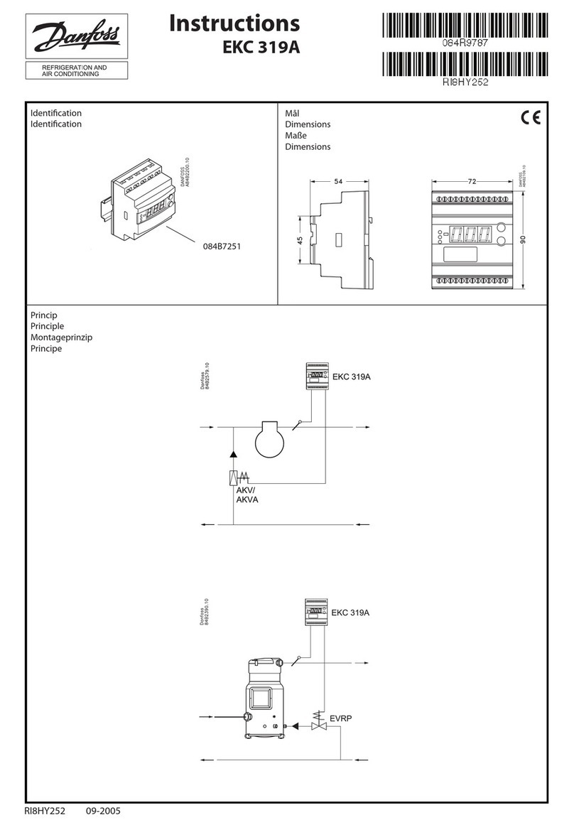
Danfoss EKC 319A User manual
Danfoss
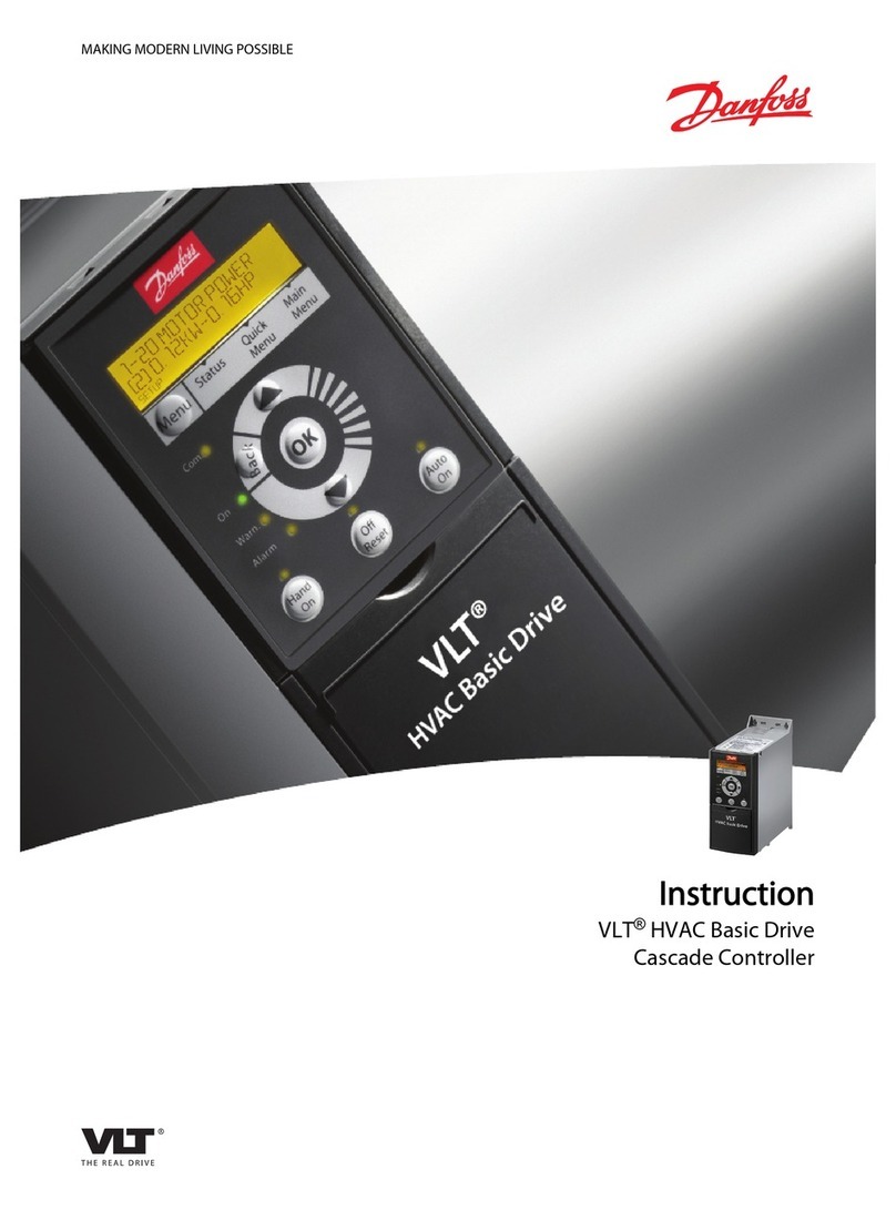
Danfoss VLT HVAC User manual
Danfoss
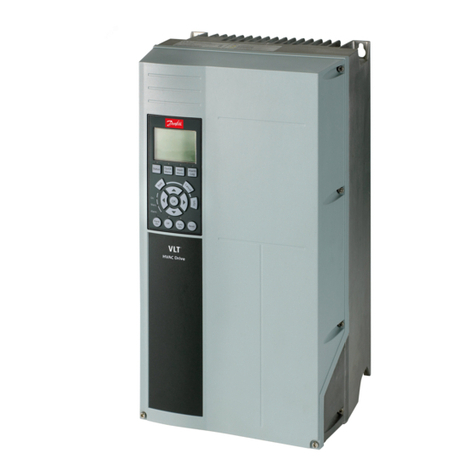
Danfoss VLT HVAC Guide
Danfoss
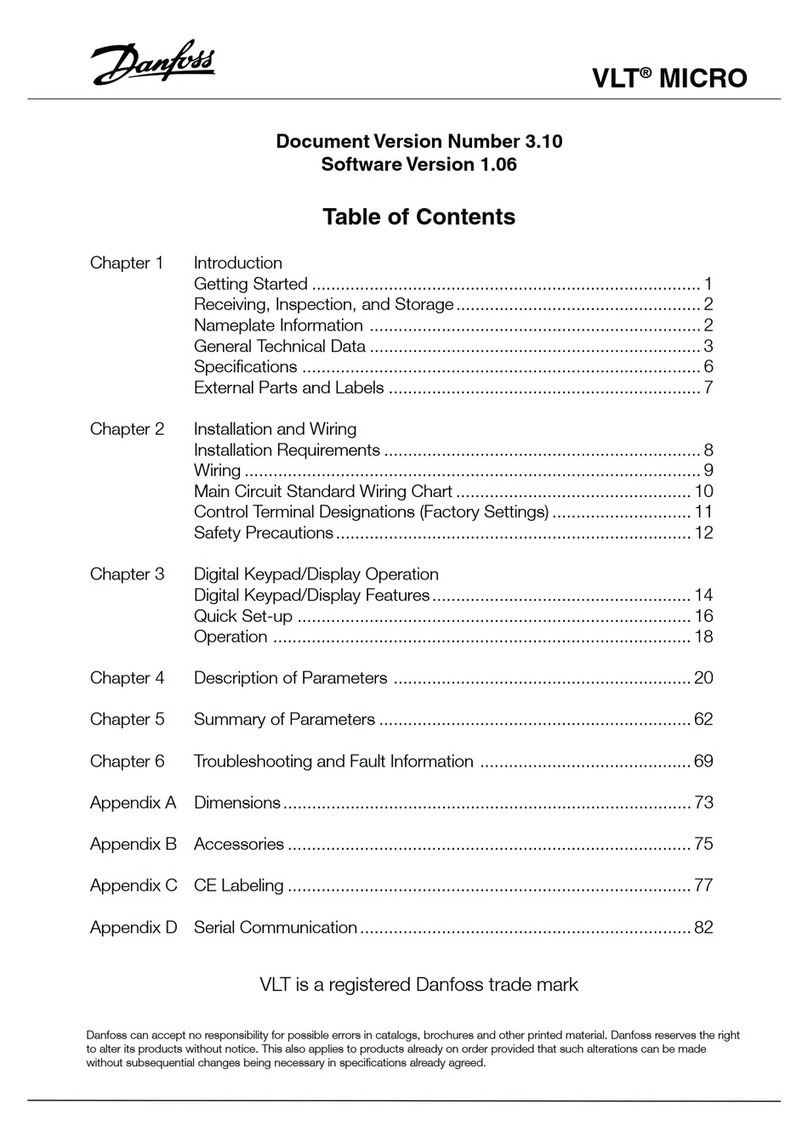
Danfoss 176F7300 User manual
Danfoss
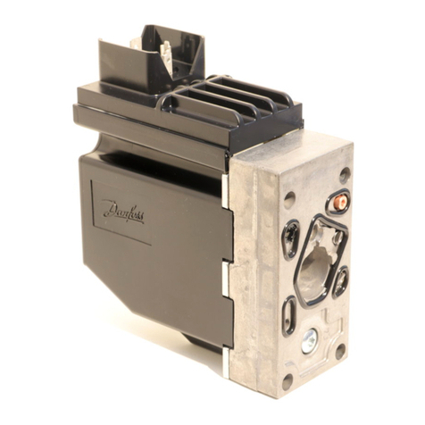
Danfoss PVE 4 Series User manual
Danfoss
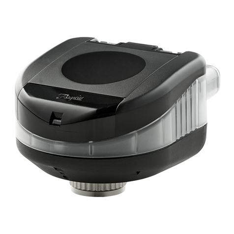
Danfoss NovoCon S Digital User manual
Danfoss
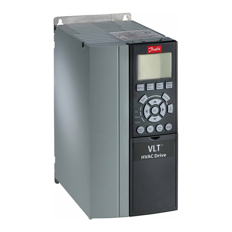
Danfoss VLT AutomationDrive FC 301 User manual
Danfoss
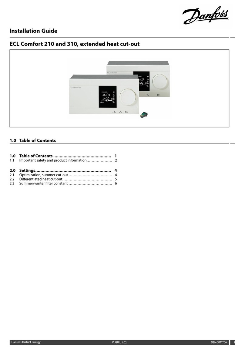
Danfoss ECL Comfort 310 User manual
Danfoss
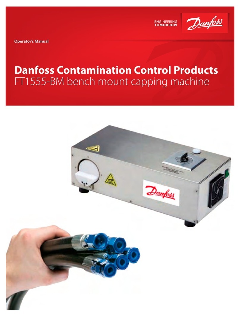
Danfoss FT1555-BM User manual
Popular Controllers manuals by other brands

Digiplex
Digiplex DGP-848 Programming guide

YASKAWA
YASKAWA SGM series user manual

Sinope
Sinope Calypso RM3500ZB installation guide

Isimet
Isimet DLA Series Style 2 Installation, Operations, Start-up and Maintenance Instructions

LSIS
LSIS sv-ip5a user manual

Airflow
Airflow Uno hab Installation and operating instructions

