manuals.online logo
Brands
  1. Home
  2. •
  3. Brands
  4. •
  5. Danfoss
  6. •
  7. Switch
  8. •
  9. Danfoss AMV 410 User manual

Danfoss AMV 410 User manual

Instructions
6 000 007 515 DEBC 11 / 02 VI.AC.K1.5V 1
AMV410, AMV 413
End Switches
Endschalter
Contacts de fin
Przełączników Krańcowych
111 12 13 14 15 16 20 21 22
PE
L R
1 2 1 2
44
S1 S2
End switches
CV
C
M
23
47
89
10
N
L
Pot
5 k
W
ax. 1W
1 2 3
17 18
anual
AMV 413
230 V AC
3-position step 3 Punkt Schritt- Régulateur Regulacja
controller Regler 3 - points sygnałem 3 – punktowym
Open valve Ventil Öffnen Ouvrir la vanne Zawór otwarty
(CloseVFU2) (VFU2 Schliessen) (VFU 2 fermée) (VFU 2 zamknięty
Close valve Ventil Schließen Fermée la vanne Zawór zamknięty
(OpenVFU2) (VFU2 Öffnen) (OuvrirVFU2) (VFU 2 otwarty)
➀
Power Spannungs- Alimentation Napięcie
supply versorgung zasilania
Valve open Ventil auf Vanne ouverte Zawór otwarty
(VFU2 closed) (VFU2 zu) (VFU2 fermée) (VFU 2 zamknięty)
End switsches Endschalter Contacts fin Przełączniki
de course krańcowe
Valve closed Ventil zu Vanne fermée Zawór zamknięty
(VFU2 open) (VFU2 auf) (VFU2 ouverte) (VFU 2 otwarty)
Pot Potentiometer Potentiometer Potencjometr
Valveopen Ventil auf Vanne ouverte Zawór otwarty
(VFU2 closed) (VFU2 zu) (VFU2 fermée) (VFU2 zamknięty)
Stroke Hub Course Skok
Valve closed Ventil zu Vanne fermée Zawór zamknięty
(VFU2opened) (VFU2 auf) (VFU2 ouverte) (VFU 2 otwarty)
1. 2. 3.
4.
5.
AMV410, AMV413
Potentiometer see page 4
Potentiometer siehe Seite 4
Potencjometra Patrz strona 4
2
DEUTSCH
Einstellung der
Endschalter
Nur spezielle Stellantriebs-
typen sind mit
Endschaltern ausgeführt,
siehe Typenschild.
Endschalter
“Antriebsstange
ausgefahren” einstellen
1. Taster drücken ➁bis
das Ventil ➂ganz
geschlossen ist
(VFU 2 ➃ganz geöffnet
ist) und die
Laufrichtungsanzeige ➄
zum Stillstand kommt
Hubanzeige beachten,
sie muss bis Position ➅
fahren
2. An Klemmen 14 und 16
ein Ohmmeter
anschließen
ENGLISH
Adjusting the End
Switches
Only special actuator types
are equipped with end
switches, see rating plate.
Adjusting the End Switch
“Stem extended”
1. Press pushbutton ➁
until the valve ➂is
completely closed
(VFU 2 ➃completely
open) and the direction
indicator ➄stops.
Observe stroke indicator,
it must move to position
➅.
2. Connect terminals 14
and 16 to an ohmmeter.
FRANCAIS
Réglage des
contacts fíns de
course
Seuls des types de moteurs
spéciaux sont équipés de
contacts fins course, voir
plaque signalétique
Régler le contact fin de
course «tige du moteur
descendue»
1. Presser la touche ➁
jusqu’à ce que la vanne
➂soit totalement fermée
(VFU2 ➃totalement
ouverte) et l’indicateur de
sens de fonctionnement
➄soit arrêté
Observer l’indication de
course, elle doit aller en
position ➅
2. Raccorder un ohmmètre
aux bornes 14 et 16
POLSKI
Regulacja
przełączników
krańcowych.
Tylko siłowniki w wersji
specjalnej są wyposażone
w przełączniki krańcowe,
patrz tabliczka
znamionowa.
Regulacja przełączników
krańcowych „ Trzpień
wysunięty”
1. Nacisnąć przycisk ➁aż
do całkowitego
zamknięcia zaworu ➂
(VFU 2 ➃całkowicie
otwarty) i zatrzymania
wskaźnika poziomu ➄.
Obserwować wskaźnik
poziomu, musi osiągnąć
pozycję ➅
2. Podłączyć zaciski 14 i
16 do omomierza.
➁
➂➃ VFU 2
➅
➄
11 12 13 14 15 16
1 2 1 2
44
S1 S2
End switches
Ω
3
DEUTSCH
3.Schraube ➀drehen, bis
der Schaltnocken ➈ den
Endschalter ➉ schaltet
und das Ohmmeter 0 Ω
anzeigt
Endschalter
“Antriebsstange
eingefahren” einstellen
1.Taster drücken ➃bis
das Ventil ➄ganz
geöffnet ist ( VFU 2 ➅
ganz geschlossen ist)
und die Laufrichtungs-
anzeige ➆zum
Stillstand kommt
2. An Klemmen 11 und 12
ein Ohmmeter
anschließen
3.Schraube ➇drehen, bis
der Schaltnocken ➈ den
Endschalter ➉ schaltet
und das Ohmmeter 0 Ω
anzeigt
➻Endschalter sind
eingestellt
ENGLISH
3.Turn screw ➀until the
cam ➈ switches the end
switch ➉ and the
ohmmeter shows 0 Ω.
Adjusting the End Switch
“Stem retracted”
1. Press pushbutton ➃
until the valve ➄is
completely open
(VFU 2 ➅ completely
closed) and the direction
indicator ➆stops.
2. Connect terminals 11
and 12 to an ohmmeter.
3.Turn screw ➇until the
cam ➈switches the end
switch ➉and the
ohmmeter shows 0 Ω.
➻The end switches are
adjusted.
FRANCAIS
3.Tourner la vis ➀jusqu’à
ce que le commutateur
➈commute le contact fin
de course ➉et que
l’ohmmètre indique 0 Ω
Régler le contact fin de
course «tige du moteur
rétractée»
1. Presser la touche ➃
jusqu’à ce que la vanne
➄soit totalement
ouverte (VFU2 ➅
totalement fermée) et
l’indicateur de sens de
fonctionnement ➆soit
arrêté
2. Raccorder un ohmmètre
aux bornes 11 et 12
3.Tourner la vis ➇jusqu’à
ce que le commutateur
➈commute le contact fin
de course ➉et que
l’ohmmètre indique 0 Ω
➻Les contacts fins de
course sont réglés
POLSKI
3. Przekręcać śrubę ➀aż
krzywka ➈spowoduje
przełączenie
przełączników
krańcowych ➉, a
omomierz wskaże 0 Ω.
Regulacja przełączników
krańcowych „ Cofnięty
trzpień”
1. Nacisnąć przycisk ➃do
całkowitego otwarcia
zaworu ➄(VFU 2 ➅
całkowicie zamknięty) i
zatrzymania wskaźnika
poziomu ➆.
2. Połącz zacisk 11 i 12 do
omomierza.
3. Przekręcać śrubę ➇aż
krzywka ➈rozłączy
przełącznik krańcowy ➉,
a omomierz wskaże 0 Ω
➻ Przełączniki krańcowe
są nastawione.
➆
➃
11 12 13 14 15 16
1 2 1 2
44
S1 S2
End switches
Ω
➀
➄ VFG.., ➅ VFU 2
➈
➇➉
4
AMV410, 413
Potentiometer
Potentiometer
Potencjometra 1. 2.
3. 4.
blue blau
yellow gelb
red rot
5
DEUTSCH
Einstellung
Potentiometer
Nur spezielle Stellantriebs-
typen sind mit dem
Potentiometer ausgeführt,
siehe Typenschild.
Nach jeder Montage
Stellantrieb und Ventil und
nach Entfernen der
Montageschraube
folgendes durchführen:
Nullpunkt justieren
1.Taster drücken ➀ bis
das Ventil ➁ganz
geschlossen ist
(VFU 2 ➂ ganz
geöffnet ist) und die
Laufrichtungsanzeige ➃
zum Stillstand kommt
Hubanzeige beachten,
sie muss bis Position ➄
fahren
2.Hubeinstellschraube ➅
2 Umdrehungen aus
dem Muttergewinde
herausdrehen
ENGLISH
Potentiometer
Settings
Only special actuator types
are equipped with
potentiometers,
see rating plate.
After having mounted a
valve and an actuator and
after having removed the
mounting screw, carry out
the following steps:
Adjust zero point
1. Press pushbutton ➀
until the valve ➁is
completely closed
(VFU 2 ➂ completely
open) and the direction
indicator ➃ stops.
Observe stroke indicator,
it must move to position
➄.
2.Unscrew stroke setting
screw ➅ by 2 turns out
of the female thread.
FRANCAIS
Réglage du
potentiomètre
Seuls des types de moteurs
spéciaux sont équipés d’un
potentiomètre, voir plaque
signalétique
Après chaque montage du
moteur et de la vanne et
après avoir retirer la vis de
montage, procéder comme
suit
Ajustement du point zéro
1. Presser la touche ➀
jusqu’à ce que la vanne
➁soit totalement fermée
(VFU2 ➂totalement
ouverte) et l’indicateur de
sens de fonctionnement
➃soit arrêté
Observer l’indication de
course, elle doit aller en
position ➄
2. Dévisser la vis de réglage
de course ➅de 2 tours
POLSKI
Nastawy
potencjometra
Tylko siłowniki wersji
specjalnej są wyposażone
w potencjometry, patrz
tabliczka znamionowa.
Po montażu zaworu i
siłownika oraz usunięciu
śruby montażowej
przeprowadzić następujące
kroki:
Regulacja punktu zero.
1. Nacisnąć przycisk ➀aż
do całkowitego
zamknięcia zaworu 
(VFU 2 ➂całkowite
otwarcie) oraz
zatrzymania wskaźnika
poziomu ➃.
Obserwować wskaźnik
poziomu musi osiągnąć
pozycję ➄.
2. Odkręcić śrubę nastawy
skoku ➅dwa obroty w
gwincie wewnętrznym.
➀
➁➂ VFU 2
➄
➃
➅
6
ENGLISH
3.Press pushbutton ➀
until the valve is
completely open
(VFU 2 completely
closed) and the direction
indicator ➁stops.
4.Press pushbutton ➂
until the valve ➁is
completely closed
(VFU 2 completely
open) and the direction
indicator ➁stops.
➻ The zero point of the
potentiometer is
adjusted
5.Then, adjust the stroke,
see page 12
Note
The range 0- 1, 2, 5, 10 kΩ
corresponds to the
maximum stroke (20 mm)
of the actuator.
After the stroke is adjusted,
the resistance must be
measured in accordance
with the valve stroke.
FRANCAIS
3. Presser la touche ➀
jusqu’à ce que la vanne
soit totalement ouverte
(VFU2 totalement
fermée) et l’indicateur de
sens de fonctionnement
➁soit arrêté
4. Presser la touche ➂
jusqu’à ce que la vanne
soit totalement fermée
(VFU 2 totalement
ouverte) et l’indicateur de
sens de fonctionnement
➁soit arrêté
➻➻
➻➻
➻Le point zéro du
potentiomètre est
ajusté
5. Ensuite procéder au
réglage de la course ,
voir page 12
Indication
La plage 0- 1, 2, 5, 10 kΩ
correspond à la course
maximum (20 mm) du
moteur. Après le réglage de
la course, la valeur de
résistance doit être
mesurée en fonction de la
course de la vanne.
POLSKI
3. Nacisnąć przycisk ➀aż
do całkowitego otwarcia
zaworu (VFU 2
całkowitego zamknięcia)
i zatrzymania wskaźnika
poziomu ➁.
4. Nacisnąć przycisk ➂aż
do całkowitego
zamknięcia zaworu ‚
(VFU 2 całkowitego
otwarcia) i zatrzymania
wskaźnika poziomu ➁.
➻➻
➻➻
➻ Punkt zero
potencjometra jest
nastawiony
5. Następnie
przeprowadzić regulację
skoku, patrz strona 12.
Uwaga
Zakres 0- 1, 2, 5, 10 kΩ
odpowiada skokowi
maksymalnemu (20mm)
siłownika.
Po regulacji skoku
rezystancja musi być
mierzona zgodnie ze
skokiem zaworu.
➀
➁
➂
0 20
mm
0
1 kΩ
2 kΩ
5 kΩ
10 k Ω
Stroke
Hub
Course
Skok
3.Taster drücken ➀bis
das Ventil ganz geöffnet
ist (VFU 2 ganz
geschlossen ist) und die
Laufrichtungs-anzeige
➁zum Stillstand kommt
4.Taster drücken ➂bis
das Ventil ganz
geschlossen ist (VFU 2
ganz geöffnet ist) und
die Laufrichtungs-
anzeige ➁zum
Stillstand kommt
➻ der Nullpunkt des
Potentiometers ist
justiiert
5. Anschließend die
Hubeinstellung
durchführen,
siehe Seite 12
Hinweis
Der Bereich
0- 1, 2, 5, 10 kΩ entspricht
dem Maximalhub (20 mm)
des Stellantriebs. Nach der
Hubeinstellung muss der
Widerstandswert
entsprechend dem
Ventilhub gemessen
werden.
DEUTSCH

Other manuals for AMV 410

2

This manual suits for next models

1

Other Danfoss Switch manuals

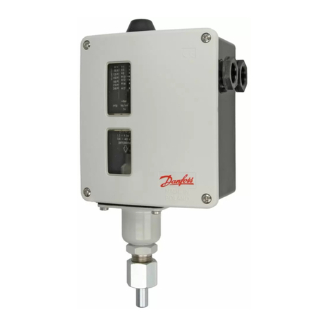
Danfoss MP 54 User manual

Danfoss

Danfoss MP 54 User manual

Danfoss RT 260A User manual

Danfoss

Danfoss RT 260A User manual

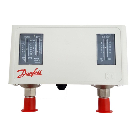
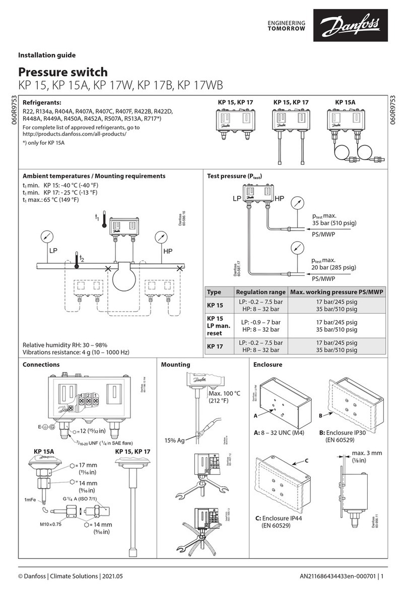
Danfoss KP 15 User manual

Danfoss

Danfoss KP 15 User manual
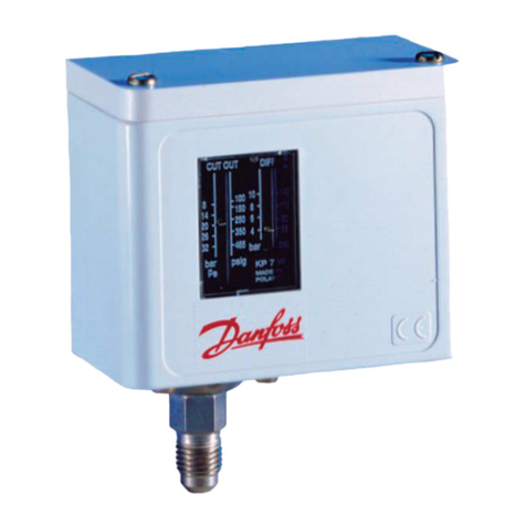
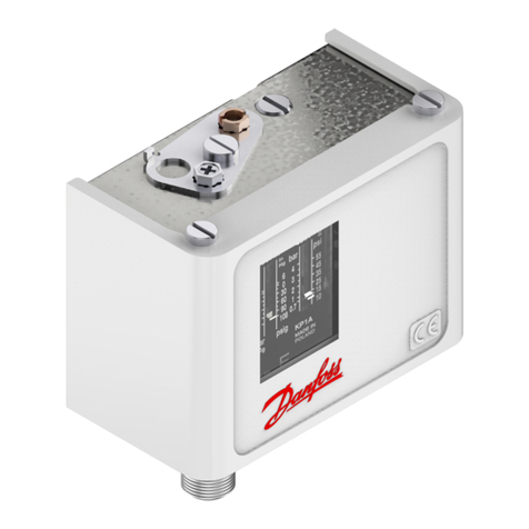
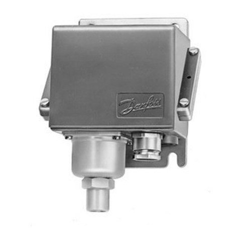
Danfoss KP 1 User manual

Danfoss

Danfoss KP 1 User manual

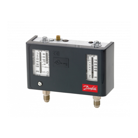
Danfoss KPU Series User manual

Danfoss

Danfoss KPU Series User manual

Danfoss KP 34 User manual

Danfoss

Danfoss KP 34 User manual

Danfoss MBC 5000 User manual

Danfoss

Danfoss MBC 5000 User manual

Danfoss MP 55 User manual

Danfoss

Danfoss MP 55 User manual

Danfoss KPU 1 User manual

Danfoss

Danfoss KPU 1 User manual
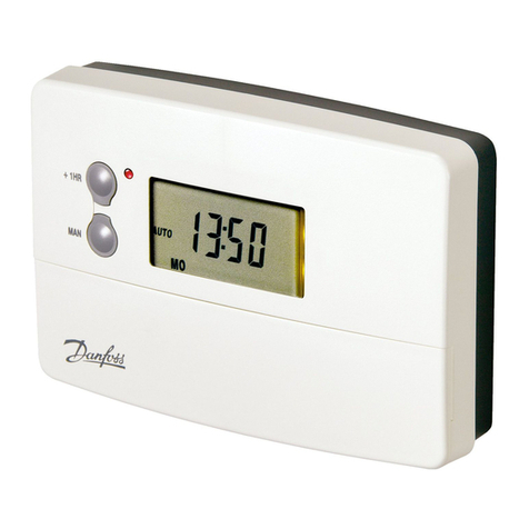
Danfoss KP 1E User manual

Danfoss

Danfoss KP 1E User manual

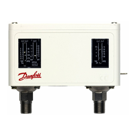
Danfoss KP 44 User manual

Danfoss

Danfoss KP 44 User manual
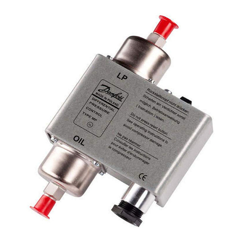
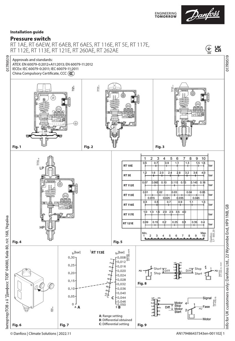
Danfoss RT 260A User manual

Danfoss

Danfoss RT 260A User manual

Danfoss PVG 32 User manual

Danfoss

Danfoss PVG 32 User manual

Danfoss KP 1A User manual

Danfoss

Danfoss KP 1A User manual

Danfoss LLS 4000 Installation and maintenance instructions

Danfoss

Danfoss LLS 4000 Installation and maintenance instructions

Danfoss KP 21 User manual

Danfoss

Danfoss KP 21 User manual

Danfoss KPS 35 User manual

Danfoss

Danfoss KPS 35 User manual
Danfoss KP 7ABS User manual

Danfoss

Danfoss KP 7ABS User manual

Danfoss RT 1AL User manual

Danfoss

Danfoss RT 1AL User manual

Danfoss RT 113 User manual

Danfoss

Danfoss RT 113 User manual
Danfoss KPI 34 User manual

Danfoss

Danfoss KPI 34 User manual

Danfoss RT 6AEW User manual

Danfoss

Danfoss RT 6AEW User manual

Danfoss RT 262A User manual

Danfoss

Danfoss RT 262A User manual

Danfoss RT 30AW User manual

Danfoss

Danfoss RT 30AW User manual

Popular Switch manuals by other brands

D-Link DES-1008P user guide

D-Link

D-Link DES-1008P user guide

D-Link DU-H4 user manual

D-Link

D-Link DU-H4 user manual

D-Link DGS-1100-10MP Quick installation guide

D-Link

D-Link DGS-1100-10MP Quick installation guide

Avenview DVI-GS3 Series Specification sheet

Avenview

Avenview DVI-GS3 Series Specification sheet

Broadcast Tools RM-3 Installation and operation manual

Broadcast Tools

Broadcast Tools RM-3 Installation and operation manual

KanexPro HDSC61D-4K user manual

KanexPro

KanexPro HDSC61D-4K user manual

Extron electronics DTP2 T 212 user guide

Extron electronics

Extron electronics DTP2 T 212 user guide

Crestron DigitalMedia DM-MD8X8-CPU3 product manual

Crestron

Crestron DigitalMedia DM-MD8X8-CPU3 product manual

Alcatel-Lucent 7210 SAS D Quality of service guide

Alcatel-Lucent

Alcatel-Lucent 7210 SAS D Quality of service guide

rako WCM-D instruction manual

rako

rako WCM-D instruction manual

D-Link DGS-1520-28MP Quick installation guide

D-Link

D-Link DGS-1520-28MP Quick installation guide

ehmann 6660C0026 Installation and operating manual

ehmann

ehmann 6660C0026 Installation and operating manual

Planet Networking & Communication SGS-6310 Series Quick installation guide

Planet Networking & Communication

Planet Networking & Communication SGS-6310 Series Quick installation guide

ATEN US3310 user manual

ATEN

ATEN US3310 user manual

Cisco Catalyst 3850 Getting started guide

Cisco

Cisco Catalyst 3850 Getting started guide

ifs NS3552-16P-2T-2S-V2 Quick installation guide

ifs

ifs NS3552-16P-2T-2S-V2 Quick installation guide

Edimax ES-5816P Declaration of conformity

Edimax

Edimax ES-5816P Declaration of conformity

Ubiquiti TS-5-POE ToughSwitchPoE quick start guide

Ubiquiti

Ubiquiti TS-5-POE ToughSwitchPoE quick start guide

manuals.online logo
manuals.online logoBrands
  • About & Mission
  • Contact us
  • Privacy Policy
  • Terms and Conditions

Copyright 2025 Manuals.Online. All Rights Reserved.