manuals.online logo
Brands
  1. Home
  2. •
  3. Brands
  4. •
  5. Danfoss
  6. •
  7. Switch
  8. •
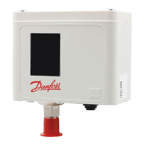
  9. Danfoss RT 6AEW User manual

Danfoss RT 6AEW User manual

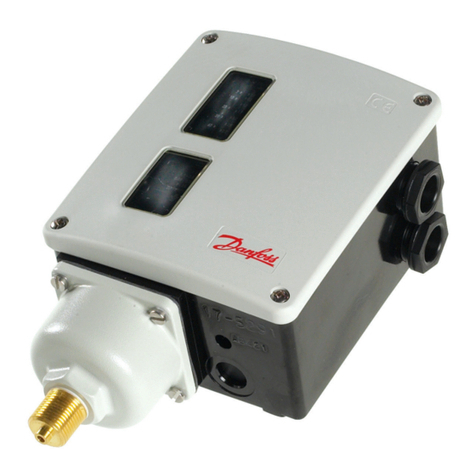
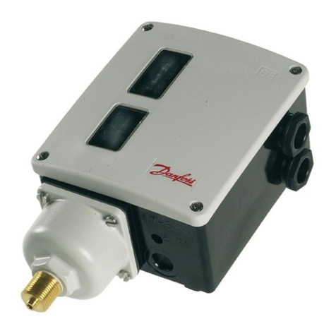
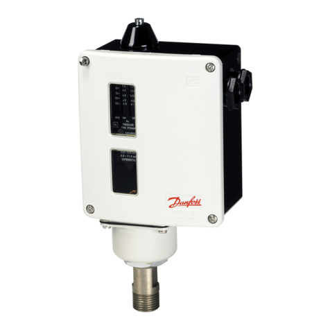
Installation guide
Pressure switch
RT 1AE, RT 6AEW, RT 6AEB, RT 6AES, RT116E, RT5E, RT 117E,
RT 112E, RT 113E, RT 121E, RT 260AE, RT 262AE
017R9519
017R9519
© Danfoss | Climate Solutions | 2022.11 AN179486437343en-001102| 1
Danf
oss
17 - 883.20
RT 1AE
RT 112E
RT 113E
RT 5E
RT 116E
RT 117E
RT 121E
Fig. 1
Fig. 4
Fig. 6 Fig. 7
Fig. 5
Fig. 8
Fig. 9
Fig. 2 Fig. 3
RT 113E
[bar]
A B
C
[bar]
A: Range setting
B: Dierential obtained
C: Dierential setting
Approvals and standards:
ATEX: EN 60079-0:2012+A11:2013; EN 60079-11:2012
IECEx: IEC 60079-0:2011; IEC 60079-11:2011
China Compulsory Certicate, CCC
Danfos
s
17-5027.10
Info for UK customers only: Danfoss Ltd., 22 Wycombe End, HP9 1NB, GB
089
:   " " 04080,  80, / 168, 
0045
0539 II2G
0539
© Danfoss | Climate Solutions | 2022.11
2 | AN179486437343en-001102
Technical data
Maximum Working Pressure:
Type RT 113E RT 112E RT 1AE RT 116E RT 5E
RT 6AEW
RT 6AEB
RT 6AES
RT 117E RT 121E RT 260AE RT 262AE
MWP
[bar] 0.4 722 22 22 34142 722 11
128 bar Pewhen used as safety equipment acc. to EN12263
Permissible ambient temperature: -20 – 65 °C
Intrinsically safe specication:
Ui = 29 V Ci = 0.5 nF
li = 0.5 A Li = 0.2 µH
Pi = 1 W
Contact load:
max. 100 mA, 30 V AC / DC
min. 1 mA, 5 V AC / DC
Must be used with a certied Ex ia barrier
satisfying the input parameters.
Installation
A set of Pg13.5 cable gland is attached to the RT in a separate bag. To
ensure IP66 (units with automatic reset) or IP54 (units with external
reset) grade of RT enclosure it is necessary to assemble this gland
as shown in the g. 6. If this gland is not used with a cable, a metal
blinding should be also assembled.
The RT pressure switch is designed for tting on the valve panel or the
compressor. Use the mounting holes (25). If the unit can be exposend
to vibration, it should be mounted on a resilient pad. If pressure
pulsations occur in the system at the point where the pressure switch
is connected, these should be eectively damped, as for example, by
connecting the RT unit to the system via damping coil.
Electrical connection (see g. 8 and g. 9)
START = make. STOP = break. DIFF = dierential.
Cable diameter: 6 – 14 mm
The earth terminal (38) should be connected to earth.
Wire dimension: min. 0,75 mm²
Adjustment
RT 1AE, RT 116E, RT 5E, RT 117E, RT 112E, RT 113E, RT 121E
(see g. 1, g. 2 and g. 8)
Set the pressure switch for minimum actuating pressure (range setting).
Setting is done by rotating the knob (5), at the same time reading the
main scale (9).
The dierential is set by rotating the dierential adjusting nut (19)
according to the nomogram concerned (g. 5 or g 7).
Maximum actuating pressure is the sum of the pressure setting and the
dierential.
RT 260AE, RT 262AE
See g. 4 and g. 8
Set the required dierential pressure with the setting disc (5) while at
the same time reading the scale (9).
RT 6AEW, RT 6AEB, RT 6AES (see g. 3 and g. 9)
After removing the seal cap (7), set the cut out pressure with the
uncovered range spindle while reading the scale (9).
Safety requirements
1. The refrigeration system must always comply with European
Ex installation standard, EN 60079-14, any local directive and
legislation as well as any other regulation applying in the area of
installation.
2. RT-E switch must be used only with reliable means of limiting
the voltage and current to prevent sparks between the contact
surfaces. The equipment to be used for electrical load limiting
must always be approved for use in the zone concerned.
3. Cable and cable entries approved for the application must be used.
Cables must not be in contact with sharp edges. The cable must
be connected with adequate stress relief in order to prevent that
pulling forces can be carried through the cable to the terminal.
4. In the event of pressure pulsations in the system, where the switch
is connected, these must be eectively damped to prevent fatigue
failure on the bellows. The cycle frequency of the RT-E switch must
be kept as low as possible. The vibration level must be kept as low
as possible.
5. It is recommended to regularly check the function of theRT-E
switch.
6. Only apparatus designed, constructed and released by Danfoss
must be used for application concerned. Danfoss can accept no
responsibility in case of alterations made on the pressure switches
or the use of them against the instructions of Danfoss.
7. Any overload of the RT switch must be prevented. Overloaded or
damaged apparatus must be exchanged.
8. Only authorised persons, who are certied in installing and
maintaining refrigration system may do the installation,
maintenance and exchange of the switch.
9. Use only appropriate tools.
10. Dispose of the switch in an environmentally-friendly way.
11. RTE switches must be installed in area where is low risk of
mechanical damage.
12. Components within the equipment can exceed the enclosure
temperature by 1K (1°C). When the media temperature exceeds
80°C, it is the responsibility of the user to ensure that the media
temperature does not cause a thermal ignition risk on parts
between the media and the switch enclosure. Maximum media
temperature on pressure switch is 100°C.
13. Isolation of the intrinsically safe circuit to ground and to the
contact mounting screw has been veried through 500VACrms
dielectric strength testing, carried out in accordance with IEC
60079-11:2011 sec tion 10.3.
14. Surface of the front cover is sputtered with stainless steel - avoid
abrasion.
15. Power must be switched o before maintenance and opening the
RT-E.
Specic conditions of use:
The enclosure fascia has been coated with a layer of stainless steel to prevent the
accumulation of electrostatic charge. In order to ensure that there is no accumulation of
electrostatic charge on the enclosure, the end user shall ensure that the external metal
work of the enclosure is locally bonded to earth. Information on the durability of the
coating with regards to use of the equipment is contained within the instruction manual.
Temperature class
Process temperature limit [°C]
T4 – T1
T5
T6
100
94
79
Product marking: RT 6AEW, RT 6AEB, RT 6AES
Ex ia IIC T6...T1 Gb-20 °C ≤ Ta ≤ 65 °C
DEMKO 14 ATEX 1406X, Rev. 3
IECEx ULD 14.0013X
Ui= 29 VIi= 0.5 APi= 1 W
Ci= 0.5 nFLi= 0.2 μH
II2G
Product marking: RT112E, RT113E, RT1AE, RT116E,
RT5E, RT117E, RT260AE, RT262AE, RT9E, RT14E,
RT101E, RT107E, RT121E, RT123E
Ex ia IIC T6...T1 Gb-20 °C ≤ Ta ≤ 65 °C
DEMKO 14 ATEX 1406X, Rev. 3
IECEx ULD 14.0013X
Ui= 29 VIi= 0.5 APi= 1 W
Ci= 0.5 nFLi= 0.2 μH
© Danfoss | Climate Solutions | 2022.11 AN179486437343en-001102 | 3
Signature:
Name: Piotr Chylaszek
Title: Sr. Spec. Projects & Approvals
Signature:
Name: Jesper Kirkegaard
Title: Engineering Director
Classified as Business
Danfoss A/S
͸Ͷ͵Ͳ

ǤǣʹͲͳ͸ͷ͹ͳͷ

ǣΪͶͷ͹Ͷͺͺʹʹʹʹ
ǣΪͶͷ͹ͶͶͻͲͻͶͻ
EU DECLARATION OF CONFORMITY
Danfoss A/S
Refrigeration & Air Conditioning Controls



Product category:
Type designation(s):
ȋȌǡȋȌȋȌǡ
Ǥ

DocuSign Envelope ID: EB2956B9-5F90-426C-9C62-1477FF35F285
© Danfoss | Climate Solutions | 2022.11
4 | AN179486437343en-001102
Signature:
Name: Piotr Chylaszek
Title: Sr. Spec. Projects & Approvals
Signature:
Name: Jesper Kirkegaard
Title: Engineering Director
Classified as Business
Danfoss A/S
͸Ͷ͵Ͳ

ǤǣʹͲͳ͸ͷ͹ͳͷ

ǣΪͶͷ͹Ͷͺͺʹʹʹʹ
ǣΪͶͷ͹ͶͶͻͲͻͶͻ
UK DECLARATION OF CONFORMITY
Danfoss A/S
Refrigeration & Air Conditioning Controls


Product category:
Type designation(s):
ȋȌǡȋȌǡȋȌ
ȋȌǡǤ

, UKSI 2016, No.
1107
(as
amended)
DocuSign Envelope ID: CB5C9C32-5050-45CA-B269-71C8F0676E66

This manual suits for next models

11

Other Danfoss Switch manuals

Danfoss CWH1000 Manual

Danfoss

Danfoss CWH1000 Manual

Danfoss RT 1AL User manual

Danfoss

Danfoss RT 1AL User manual

Danfoss KP 1A User manual

Danfoss

Danfoss KP 1A User manual

Danfoss RT 260A User manual

Danfoss

Danfoss RT 260A User manual

Danfoss KP 1 User manual

Danfoss

Danfoss KP 1 User manual

Danfoss LLS 4000 User manual

Danfoss

Danfoss LLS 4000 User manual

Danfoss KP 1E User manual

Danfoss

Danfoss KP 1E User manual

Danfoss KPU Series User manual

Danfoss

Danfoss KPU Series User manual

Danfoss LLS 4000 User manual

Danfoss

Danfoss LLS 4000 User manual

Danfoss KP 1 User manual

Danfoss

Danfoss KP 1 User manual

Danfoss TS715 Si Assembly Instructions

Danfoss

Danfoss TS715 Si Assembly Instructions

Danfoss KPS 35 User manual

Danfoss

Danfoss KPS 35 User manual

Danfoss KPI 34 User manual

Danfoss

Danfoss KPI 34 User manual

Danfoss KP 21 User manual

Danfoss

Danfoss KP 21 User manual

Danfoss RT 260A User manual

Danfoss

Danfoss RT 260A User manual

Danfoss RT 260A User manual

Danfoss

Danfoss RT 260A User manual

Danfoss KPU Series User manual

Danfoss

Danfoss KPU Series User manual

Danfoss MBC 5000 User manual

Danfoss

Danfoss MBC 5000 User manual

Danfoss RT 6W User manual

Danfoss

Danfoss RT 6W User manual

Danfoss AKS 38 User manual

Danfoss

Danfoss AKS 38 User manual

Danfoss RT 262A User manual

Danfoss

Danfoss RT 262A User manual

Danfoss KP 34 User manual

Danfoss

Danfoss KP 34 User manual

Danfoss KP 7ABS User manual

Danfoss

Danfoss KP 7ABS User manual

Danfoss BCP1H User manual

Danfoss

Danfoss BCP1H User manual

Popular Switch manuals by other brands

Digitus DN-80212 Quick installation guide

Digitus

Digitus DN-80212 Quick installation guide

Monoprice HRM-2214F user manual

Monoprice

Monoprice HRM-2214F user manual

trafag 8380 DPC instructions

trafag

trafag 8380 DPC instructions

Timing TSC 4092A IRIG-B Operation and maintenance manual

Timing

Timing TSC 4092A IRIG-B Operation and maintenance manual

StarTech.com DS8105 Spec sheet

StarTech.com

StarTech.com DS8105 Spec sheet

Vimar 6592 Installer's guide

Vimar

Vimar 6592 Installer's guide

Samsung SCQ-041AP user guide

Samsung

Samsung SCQ-041AP user guide

ICS Schneider Messtechnik PSA-31 operating instructions

ICS Schneider Messtechnik

ICS Schneider Messtechnik PSA-31 operating instructions

Ciena 3930 Series Hardware Installation and Start-up Manual

Ciena

Ciena 3930 Series Hardware Installation and Start-up Manual

MST Impact NS5001 user manual

MST

MST Impact NS5001 user manual

HP HP 2530 Manual supplement

HP

HP HP 2530 Manual supplement

Maxxima MEW-S150DW Instruction guide

Maxxima

Maxxima MEW-S150DW Instruction guide

Spirax Sarco LCS3051 Installation and maintenance instructions

Spirax Sarco

Spirax Sarco LCS3051 Installation and maintenance instructions

SMC Networks EZ Switch SMC8504T Specifications

SMC Networks

SMC Networks EZ Switch SMC8504T Specifications

sourcetec UNO installation guide

sourcetec

sourcetec UNO installation guide

Veracity CAMSWITCH 8 PLUS quick start guide

Veracity

Veracity CAMSWITCH 8 PLUS quick start guide

Hama 00011576 user manual

Hama

Hama 00011576 user manual

Linksys EtherFast EG0801W Specifications

Linksys

Linksys EtherFast EG0801W Specifications

manuals.online logo
manuals.online logoBrands
  • About & Mission
  • Contact us
  • Privacy Policy
  • Terms and Conditions

Copyright 2025 Manuals.Online. All Rights Reserved.