manuals.online logo
Brands
  1. Home
  2. •
  3. Brands
  4. •
  5. DANLERS
  6. •
  7. Security Sensor
  8. •
  9. DANLERS CEFPLL10VDC Quick start guide

DANLERS CEFPLL10VDC Quick start guide

Installation notes
DANLERS Limited, Vincients Road, CHIPPENHAM, Wiltshire, SN14 6NQ, UK.
Telephone: +44 (0)1249 443377 Fax: +44 (0)1249 443388
E-mail: [email protected] Web: www.danlers.co.uk
Company Registered Number 2570169 VAT Registration Number 543 5491 38
Products available from DANLERS
• PIR occupancy switches • Daylight linked dimmers • Manual high frequency dimmers
• Photocells • Radio remote controls • Time lag switches • Outdoor security switches
• Dimmers • Heating, ventilation and air-conditioning controls • Bespoke / O.E.M. products
Please call for more information or a free catalogue, or visit our website.
This product conforms to BS EN 60669-2-1. Product complies to Class 2 insulation.
Please ensure the most recent edition of the appropriate local wiring regulations are
observed and suitable protection is provided e.g. 6 amps over current, 1kV over voltage.
Please ensure that this device is disconnected from the supply if an insulation test is made.
This product is covered by a warranty which extends to 5 years from the date of manufacture.
Precautions and Warranty
LLL
L
L
NNNN
N
-0
+10
IN
OUT
IN
OUT
IN
OUT
-0
+10
BALLAST
LIGHT
SWITCH
OUTPUT
‘Step Down’ PIR
Occupancy Switch
eg.CEFPLL10VDC
or CESPLL10VDC
PIR Occupancy
Switch with Volt Free
secondary output
with Normally Closed
Logic Gold relay
contacts*
PIR Occupancy
Switch with Volt Free
secondary output
with Normally Closed
Logic Gold relay
contacts*
PIR Occupancy
Switch with Volt Free
secondary output
with Normally Closed
Logic Gold relay
contacts*
*Eg. DANLERS CEFPLL10VDCVFNCLG product
14/12/15 INS217 CEFPLL10VDC
Variants
Variants can be supplied to special order, please ask for details.
Troubleshooting
The load will not switch on:
• The LUX adjuster is set too low and is inhibiting the switch.
• The moving body is not emitting more IR than the background.
(Person wearing insulating clothing in a warm environment)
• Person is too far from the PIR switch, see detection diagram.
• Person is moving unusually slowly (perhaps when testing).
Loading
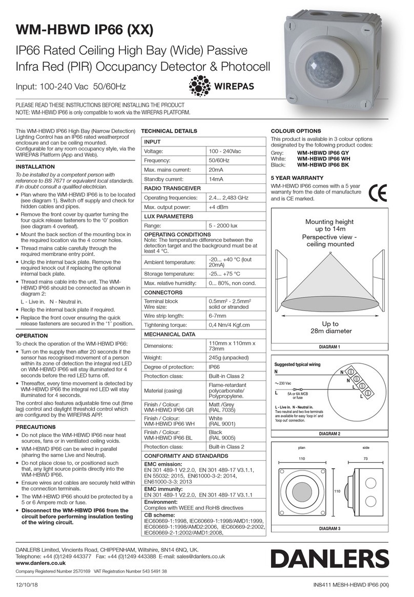
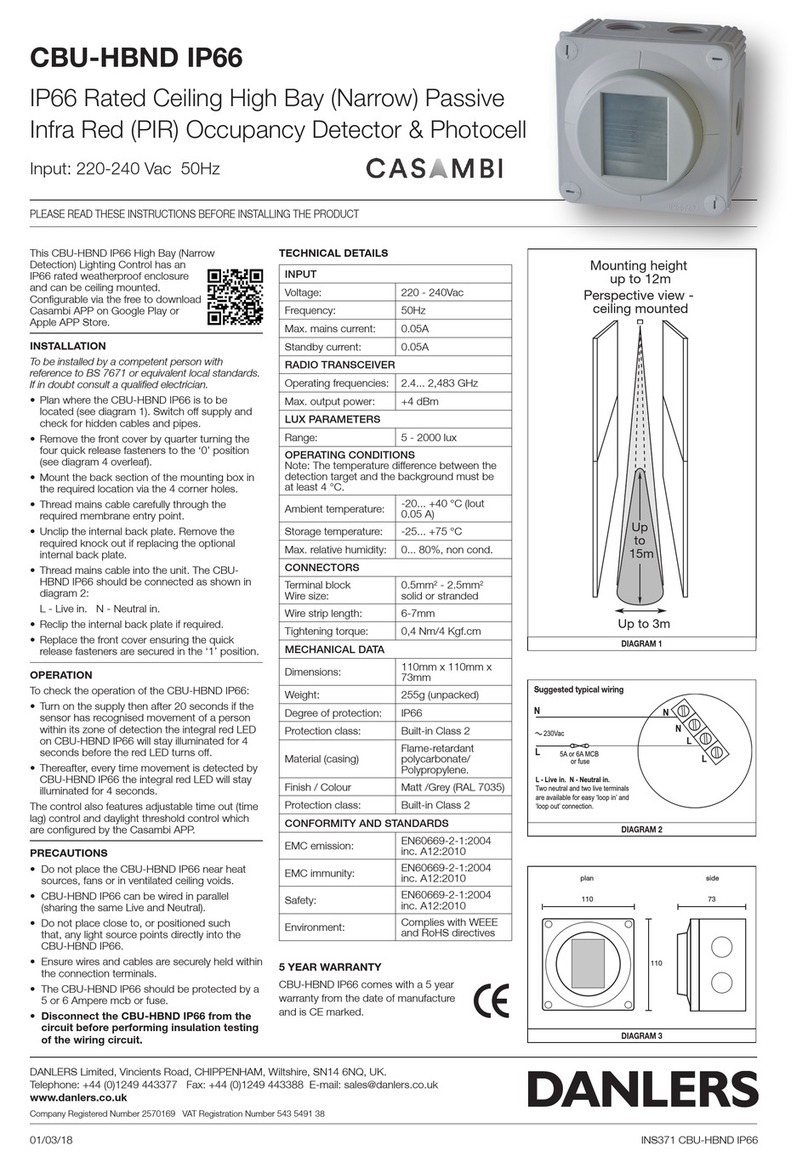
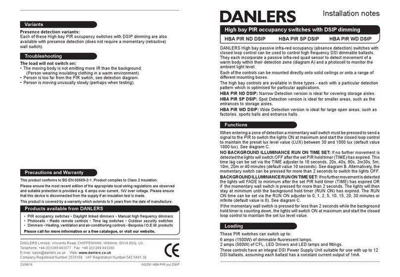
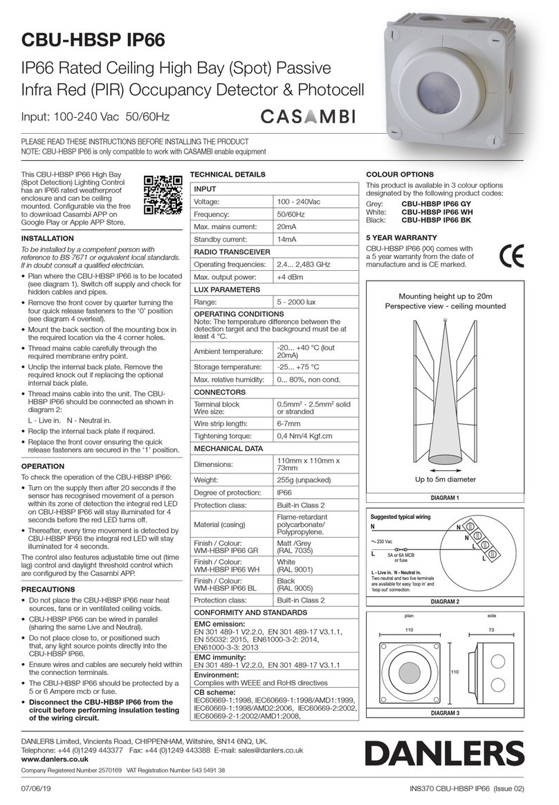
PIR occupancy switch with 1-10V
‘Step Down’ illuminance
CEFPLL10VDC CEFPLL10VDCSEAL
DANLERS passive infra-red occupancy switches with ‘Step Down’
illuminance CEFPLL10VDC (CEFPLL10VDCSEAL) can be used to
control high frequency 1-10VDC dimmable ballasts.
The products can be ush mounted into suspended and plasterboard
ceilings (diagram A). They include two 2metre connecting exes, one for
the supply and the other for the 1-10V control, this makes installation
quicker and easier. This product requires a neutral connection.
These PIR switches incorporate a passive infra-red quad sensor to
detect movement of a warm body within their detection zone (diagram
B), a photocell to monitor the ambient light level and a adjustment
spindle to select the level of ‘Step Down’ illuminance.
Upon detecting movement, the PIR will switch the 1-10V dimmable
ballast to 100% on via the Switched Line output if the room is darker
than the setting on the rst lux adjuster (LUX, diagram D).
Upon non-occupation the 1-10V dimmable ballast will switch to a
pre-set lower light level (‘Step Down’ illuminance), variable from 10%
to 100% in 9 steps.
There is also a time lag function for adjusting the time that must elapse
with no movement detected before the PIR switch will switch to its
lower ‘Step Down’ level. This time lag can be set via the TIME adjuster
to 10 seconds, 20s, 40s, 1 minute 15 seconds, 2m30s, 5m, 10m, 20m
or 40 minutes (diagram D).
CEFPLL10VDCSEAL is protected against light splashes and
condensation and is suitable for use in toilets and bathrooms (zones
2 and 3).
These PIR switches can control up to 20x 1-10V dimmable ballasts,
assuming each ballast has a constant current output of 1mA.
E: Wiring diagram for corridors and larger areas
Installation procedure
1. Please read these notes carefully before commencing work.
In case of doubt please consult a qualied electrician.
2. POSITIONING: The CEFPLL10VDC (SEAL) should be installed to achieve
correct coverage of the area, see diagram B.
Avoid locating this product
where it is exposed to drafty conditions (exposed lobbies, open ceiling
voids or near fans) or near heat sources.
3. To cover larger areas and corridors PIRs should be spaced in a 5 metre
grid formation, with one CEFPLL10VDC(SEAL) and the rest with switching
PIRs with Volt Free secondary output and Normally Closed, Logic Gold relay
contacts (CEFLPIRVFNCLG) with all Switch Line outputs wired in series
(diagram E).
4. Make sure the power is isolated from the circuit.
The PIR should be connected as shown in diagram C:
Thick wire Thin wire
Brown L Live in Red +1-10V control
Blue N Neutral in Blue -0V reference
Start-up mode
When the PIR is powered up, it will switch on the load for 1 minute, the load
will then switch off and the PIR will enter its Operating Mode. If a manual
override-off switch is positioned before the PIR in the circuit (diagram C,
note 1) it will do this each time the wall switch is switched on. Alternatively,
if the wall switch is placed after the PIR (diagram C, note 2) it will not enter
the start-up mode each time.
Time, Lux and ‘Step Down’ set-up
For convenience, ensure that the TIME is set to the minimum when setting up
the LUX level.Afterwards set the TIME to a value suitable for the application.
The LUX is best set up when the local ambient light is at approximately
the minimum desired working light level. With the LUX set fully clockwise
wait for the PIR to switch off. Rotate the LUX adjuster slowly anticlockwise
(- to +), whilst waving your hand approximately 1m below the PIR, until the
load switches on.
The single adjuster spindle on the back of the PIR is used to regulate the ‘Step
Down’ illuminance function lux level, see diagram E opposite. This must be
adjusted in situ so that the desired level of brightness is achieved under the
luminaire(s) being controlled. In areas where no natural daylight is present it
is advised that the LUX level is set to . inhibit off.
Clearance hole
63 or 64mm (2.5") diameter
Springs can either be left closed (down
the side of the product) or opened out.
L
N
1
tsallab
10
1
tsallab
10
1
tsallab
10
CEFPLL10VDC(SEAL)
control lines
230 VAC
Optional
switch for
overriding off
TIME
minmax
20s
40s
1m15s
2m30s
5m
10m
10s
20m
40m
LUX
maxmin
100 ∞
1000
Typical settings
up to 5m
up to 7m
Strong detection zone
i.e. person moving arm
or walking towards PIR
Secondary detection zone
i.e. person walking
perpendicular to PIR
For optimum coverage
recommended mounting
height: 2.4 to 5m
A: Mounting diagram
B: Detection diagram
C: Wiring diagram, single PIR D: Adjusting time and lux
at the side of product
‘Step Down’ set-up
The STEP DOWN low light level range is adjusted
via the spindle on the top of the product and allows
the 1-10VDC ballast to switch from 10% to 100% in
9 steps. Fully clockwise will allow the ballast to switch
to 100% on non-occupation. Fully anti-clockwise will
allow the ballast to switch to 10% on non-occupation.
E: ‘Step Down’ adjuster
at the top of the product
‘Step Down’
adjuster
1
00
%
10%
Adjuster
guide
Switching Flex
Control
Flex

This manual suits for next models

1

Other DANLERS Security Sensor manuals

DANLERS EasyZAPP EZ CEFL DALI Quick start guide

DANLERS

DANLERS EasyZAPP EZ CEFL DALI Quick start guide

DANLERS CBU-HBSP User manual

DANLERS

DANLERS CBU-HBSP User manual

DANLERS MWCEFL Quick start guide

DANLERS

DANLERS MWCEFL Quick start guide

DANLERS WM-HBWD IP66 Series User manual

DANLERS

DANLERS WM-HBWD IP66 Series User manual

DANLERS CBU-HBWD IP66 User manual

DANLERS

DANLERS CBU-HBWD IP66 User manual

DANLERS HBA PIR ND DSIP Quick start guide

DANLERS

DANLERS HBA PIR ND DSIP Quick start guide

DANLERS COPD Quick start guide

DANLERS

DANLERS COPD Quick start guide

DANLERS COPD17M Quick start guide

DANLERS

DANLERS COPD17M Quick start guide

DANLERS SILVAIR MESH-HBWD DALI User manual

DANLERS

DANLERS SILVAIR MESH-HBWD DALI User manual

DANLERS CBU-HBND IP66 User manual

DANLERS

DANLERS CBU-HBND IP66 User manual

DANLERS COPD Quick start guide

DANLERS

DANLERS COPD Quick start guide

DANLERS WM-HBND IP66 Series User manual

DANLERS

DANLERS WM-HBND IP66 Series User manual

DANLERS DBPSU Quick start guide

DANLERS

DANLERS DBPSU Quick start guide

DANLERS CBU-HBWD IP66 Series User manual

DANLERS

DANLERS CBU-HBWD IP66 Series User manual

DANLERS WM-HBSP IP66 Series User manual

DANLERS

DANLERS WM-HBSP IP66 Series User manual

Popular Security Sensor manuals by other brands

Ultra-safe US-96760-120 User instruction manual

Ultra-safe

Ultra-safe US-96760-120 User instruction manual

X-Stand FREEDOM HARNESS Assembly and user's manual

X-Stand

X-Stand FREEDOM HARNESS Assembly and user's manual

Safe Signal WFDTNRN Installation and maintenance instructions

Safe Signal

Safe Signal WFDTNRN Installation and maintenance instructions

WABCO TAILGUARD manual

WABCO

WABCO TAILGUARD manual

PCB Piezotronics 320C03 Installation and operating manual

PCB Piezotronics

PCB Piezotronics 320C03 Installation and operating manual

ZyAura ZGw19 operating instructions

ZyAura

ZyAura ZGw19 operating instructions

Fike FIK-W-PHOTO Installation and maintenance instructions

Fike

Fike FIK-W-PHOTO Installation and maintenance instructions

POLARA iPHCU3W quick start

POLARA

POLARA iPHCU3W quick start

SICK KTX-WB9114125A Series manual

SICK

SICK KTX-WB9114125A Series manual

Bircher Reglomat PrimeTec B Original instructions

Bircher Reglomat

Bircher Reglomat PrimeTec B Original instructions

Chauvin Arnoux C.A 711 user manual

Chauvin Arnoux

Chauvin Arnoux C.A 711 user manual

SICK GTE6V operating instructions

SICK

SICK GTE6V operating instructions

BUCKINGHAM MFG 488 Series Replacement instructions

BUCKINGHAM MFG

BUCKINGHAM MFG 488 Series Replacement instructions

careium Ellis quick start guide

careium

careium Ellis quick start guide

Honeywell Notifier FSP-951AUS Installation and maintenance instructions

Honeywell

Honeywell Notifier FSP-951AUS Installation and maintenance instructions

DINUY DM TEC 008 instruction manual

DINUY

DINUY DM TEC 008 instruction manual

Theben TA 4 S DALI-2 manual

Theben

Theben TA 4 S DALI-2 manual

Gossen MetraWatt METRAFUSE FD PRO operating instructions

Gossen MetraWatt

Gossen MetraWatt METRAFUSE FD PRO operating instructions

manuals.online logo
manuals.online logoBrands
  • About & Mission
  • Contact us
  • Privacy Policy
  • Terms and Conditions

Copyright 2025 Manuals.Online. All Rights Reserved.