manuals.online logo
Brands
  1. Home
  2. •
  3. Brands
  4. •
  5. DANLERS
  6. •
  7. Security Sensor
  8. •
  9. DANLERS COPD Quick start guide

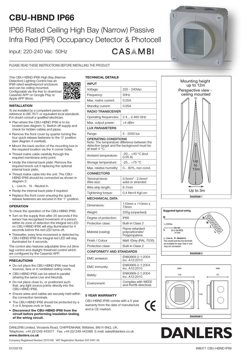
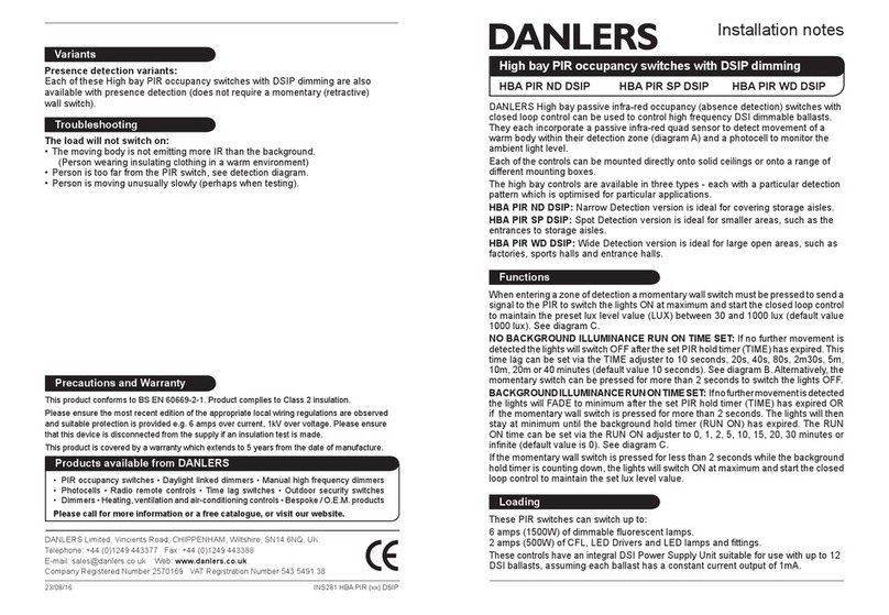
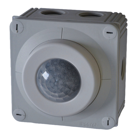
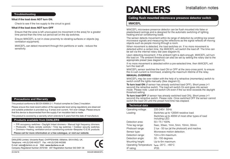
DANLERS COPD Quick start guide

Installation notes
DANLERS Limited, Vincients Road, CHIPPENHAM, Wiltshire, SN14 6NQ, UK.
Telephone: +44 (0)1249 443377 Fax: +44 (0)1249 443388
E-mail: [email protected] Web: www.danlers.co.uk
Company Registered Number 2570169 VAT Registration Number 543 5491 38
Products available from DANLERS
• PIR occupancy switches • Daylight linked dimmers • Manual high frequency dimmers
• Photocells • Radio remote controls • Time lag switches • Outdoor security switches
• Dimmers • Heating, ventilation and air-conditioning controls • Bespoke / O.E.M. products
Please call for more information or a free catalogue.
This product conforms to BS EN 60669-2-1 and BS EN 55015.
Please ensure the most recent edition of the appropriate local wiring regulations are observed
and suitable protection is provided e.g. a 10 amp circuit breaker and voltage surge protection.
Please ensure that this device is disconnected from the supply if an insulation test is made.
This product is covered by a warranty which extends to 5 years from the date of manufacture.
Precautions and Warranty
Compact person detector, PIR switch
COPD COPD BK
DANLERS Compact Person Detector is IP66 rated and can be
surface mounted onto an external wall. It incorporates a passive
infra-red quad sensor to detect movement of a warm body within
the detection zone (diagram A) and the COPD (BK) includes a
photocell to monitor the ambient light level.
The detection range is about 10 metres over 120 degrees, the range
reduces to about 8m at the extremes to prevent nuisance switching.
On detecting movement, if the ambient light is dark enough, the
COPD (BK) will switch the load on. The ambient threshold can be
set by the user to between approximately 10 and 1000 lux via the
internal LUX adjuster (diagrams B and C). The photocell can be
disabled via the internal mode button (see overleaf).
If no more movement is detected within a pre-selected time,
then the PIR switch will turn the load off. This time lag can be set
via the TIME adjuster to 10 seconds, 20 seconds, 40 seconds,
80 seconds, 2 minutes 30 seconds, 5 minutes,10 minutes, 20
minutes or 40 minutes (diagram D).
Product codes:
COPD Grey enclosure
COPD BK Black enclosure
Loading
The switch should only be connected to a 230V 50Hz AC supply.
These PIR switches can switch up to:
6 amps (1500W) of resistive loads.
6 amps (1500W) of uorescent loads.
3 amps (750W) of electronic and wire wound transformer loads.
2 amps (500W) of CFL, 2D lamps, LED Drivers and LED lamps
and ttings.
1 amp (250W) of fans
Minimum load 2W resistive, suitable for most energy saving lamps,
LEDs and emergency ttings.
01/03/19 INS970 COPD
Variants
Low voltage variants can be supplied, coded by the following sufxes:
• 12VAC 12V - (ac supply) operation
• 12VDC 12V - (dc supply) operation
• 24VAC 24V - (ac supply) operation
• 24VDC 24V - (dc supply) operation
Trouble shooting
The COPD cannot be made to switch on during bright days
• The COPD should have the lux set to inactive via the internal mode
button (see diagram B)
The PIR does not detect
• Person is too far from the COPD switch, see detection diagram.
• Person is moving unusually slowly (perhaps when testing).
The PIR stops working
• Ensure the unit is mounted correctly so that no water can enter.
The PIR False triggers
• Detector is exposed to air movement on breezy days.
Dual colour LED:
RED - PIR active,
Photocell inactive
GREEN - PIR and
Photocell override ON
(passive LUX)
Lux Cell
Mode
Time
Delay
Spindle
Lux
Setting
Spindle
MODE
STATUS
TIME LUX
10
1000
TIME
min max
LUX
max min
10 LUX
40m
20m
10m
5m
2.5m
80s
10s
20s
40s
1000 LUX
TIME
min max
LUX
max min
10 LUX
40m
20m
10m
5m
2.5m
80s
10s
20s
40s
1000 LUX
Installation procedure
1. Please read these notes carefully before commencing work.
In case of doubt please consult a quali ed electrician.
2. The detector should be sited so that it is not shaded from daylight
3. The detector should be mounted between 1 and 2.2 metres high, via
any of the four pre-drilled mounting holes only.
4. It must be mounted with the cable entering from below.
5. Make sure the power is isolated from the circuit.
6. The detector should be connected as shown in diagram E
L - Live in, N - Neutral in, SL - Switched Line out.
7. IMPORTANT - Replace terminal cover.
8. Once the wiring has been completed and veri ed, switch on the supply
and test the operation.
Lux and Time set-up
For convenience, ensure that the TIME is set to minimum when setting up
the LUX level.Afterwards set theTIME to a value suitable for the application.
8. When powered up, (after 1 minute stabilisation time) turn lux pot
(diagram C) fully clockwise and time pot fully anticlockwise.
9. Press the MODE button (diagram B) for approximately 0.5s. The
LED will go green indicating the LUX cell is active. (Or press and
hold button for approx. 4 seconds – LED goes RED indicating Lux
cell INACTIVE). Repeating these steps will toggle the functionality.
10. If lux cell active, vacate area until PIR switch switches the load off
(should be after 10 seconds).
11. With the LUX as desired on working plane from daylight ONLY (no
arti cial light), wind the lux pot anticlockwise whilst waving your
hand in front of the PIR cell. When the PIR switches the load ON,
stop turning the pot. The Lux inhibit level is now set.
12. Turn the PIR time to the desired timeout (diagram D).
Whenever a
person is detected, the time lag will start again and the load will stay
switched on.
L
load
optional manual
wall switch for
overriding off
N
230 VAC
SL
N
A: Detection range
E: Wiring diagramD: Time adjustment
Strong detection zone
(5m) i.e. person walking
towards detector
Secondary
detection zone
(10m, 8m at
extremes)
i.e. person
walking
perpendicular to
detector
Use Mode Button to disable
LUX (see diagram B)
Inside detector housing
Recommended mounting
height 1 to 2.2 metres
COPD or COPD BK
Precondition Power-up Condition
Lux Cell Inactive
Relay OFF
Lux Cell Inactive
Relay comes ON for 1 Min. After 1 min. ready for detection.
Lux Cell Active
Relay ON
Lux Cell Active
Relay stays ON for 1 Min. After 1 min. ready for detection.
Lux Cell Active
Relay OFF
Lux Cell Active
Relay comes ON for 1 Min. After 1 min. ready for detection.
Lux Cell Inactive
Relay ON
Lux Cell Inactive
Relay stays ON for 1 Min. After 1 min. ready for detection.
C: Lux adjustment
B: Time/Lux adjusters (inside casing)
Locate safety cap plastic
pins in the hole ‘L’ and
second ‘N’ holes above
the termination screws.
Press firmly to attach.
Safety cap

This manual suits for next models

1

Other DANLERS Security Sensor manuals

DANLERS CBU-HBSP User manual

DANLERS

DANLERS CBU-HBSP User manual

DANLERS CBU-HBWD IP66 Series User manual

DANLERS

DANLERS CBU-HBWD IP66 Series User manual

DANLERS WM-HBND IP66 Series User manual

DANLERS

DANLERS WM-HBND IP66 Series User manual

DANLERS SILVAIR MESH-HBWD DALI User manual

DANLERS

DANLERS SILVAIR MESH-HBWD DALI User manual

DANLERS MWCEFL Quick start guide

DANLERS

DANLERS MWCEFL Quick start guide

DANLERS EasyZAPP EZ CEFL DALI Quick start guide

DANLERS

DANLERS EasyZAPP EZ CEFL DALI Quick start guide

DANLERS CBU-HBND IP66 User manual

DANLERS

DANLERS CBU-HBND IP66 User manual

DANLERS DBPSU Quick start guide

DANLERS

DANLERS DBPSU Quick start guide

DANLERS COPD Quick start guide

DANLERS

DANLERS COPD Quick start guide

DANLERS CBU-HBWD IP66 User manual

DANLERS

DANLERS CBU-HBWD IP66 User manual

DANLERS CEFPLL10VDC Quick start guide

DANLERS

DANLERS CEFPLL10VDC Quick start guide

DANLERS COPD17M Quick start guide

DANLERS

DANLERS COPD17M Quick start guide

DANLERS WM-HBSP IP66 Series User manual

DANLERS

DANLERS WM-HBSP IP66 Series User manual

DANLERS WM-HBWD IP66 Series User manual

DANLERS

DANLERS WM-HBWD IP66 Series User manual

DANLERS HBA PIR ND DSIP Quick start guide

DANLERS

DANLERS HBA PIR ND DSIP Quick start guide

Popular Security Sensor manuals by other brands

Textron HDE V-WATCH PRO Operating instructions manual

Textron

Textron HDE V-WATCH PRO Operating instructions manual

Waters 2489 Overview and maintenance guide

Waters

Waters 2489 Overview and maintenance guide

RIKEN RX-516 Operation manual

RIKEN

RIKEN RX-516 Operation manual

Tollco WaterFuse PlugIn VFB700-DN15 User's manual & installation instructions

Tollco

Tollco WaterFuse PlugIn VFB700-DN15 User's manual & installation instructions

Roland R1000 series E20 manual

Roland

Roland R1000 series E20 manual

AccuBANKER D500 quick start guide

AccuBANKER

AccuBANKER D500 quick start guide

Texecom Veritas Reflex instruction manual

Texecom

Texecom Veritas Reflex instruction manual

Sonel LKZ-2000 Operator's manual

Sonel

Sonel LKZ-2000 Operator's manual

3M DBI SALA Pro Series instruction manual

3M

3M DBI SALA Pro Series instruction manual

STEINEL PROFESSIONAL iHF 3D manual

STEINEL PROFESSIONAL

STEINEL PROFESSIONAL iHF 3D manual

Hytronik HMW39/RF quick start guide

Hytronik

Hytronik HMW39/RF quick start guide

System Sensor 4451HT Installation and maintenance instructions

System Sensor

System Sensor 4451HT Installation and maintenance instructions

RLE Technologies SeaHawk LD2000 user guide

RLE Technologies

RLE Technologies SeaHawk LD2000 user guide

Stanley LD100 user manual

Stanley

Stanley LD100 user manual

Konig SEC-APD10 Instructions for use

Konig

Konig SEC-APD10 Instructions for use

ELREHA EGS 101 FN S001 manual

ELREHA

ELREHA EGS 101 FN S001 manual

Joy-it BUMP-SENSOR manual

Joy-it

Joy-it BUMP-SENSOR manual

Rielta ORLAN-D installation guide

Rielta

Rielta ORLAN-D installation guide

manuals.online logo
manuals.online logoBrands
  • About & Mission
  • Contact us
  • Privacy Policy
  • Terms and Conditions

Copyright 2025 Manuals.Online. All Rights Reserved.