m-Dimension ADI-12W6 User manual

Manufacturer of Dimensions™ Inverters
4467 White Bear Parkway
St. Paul, MN 55110
Phone: 651-653-7000 Fax: 651-653-7600
E-mail: inverterinfo@sensata.com
Web: www.dimensions.sensata.com
ISO 9001:2000 Registered Company
DC to AC Power Inverters
Owners Manual for Models:
ADI-12W6
ADI-12W8
Including Options:
B3: 3-Step Battery Charger
F3: 100VAC, 60HZ Output
R: LED Remote Control/Status Panel
R3: LED Remote Control/Status Panel with
Master Disconnect
T: Transfer Switch Relay
Form: 122039B
January 2007

2 Form 122039
Table of Contents:
Section Description Page
1 Safety Instructions ..…………………………………………………..…. 3
1.1 Warning and Danger Symbols ……..……..…………….…….…………… 3
1.2 Inverter Precautions …………………………………………….……………… 3
1.3 Battery Precautions …………………….……..………………...…………… 3
2 Specifications ……..……………………..…...……………………..……. 4
3 Technical description …..……………………………………………..… 5
3.1 DC to AC Inverters …….……….…………………...…………......………… 5
3.1.1 Inverter Power Mode ………………...………………….………. 5
3.2 Available Options …………………………………………………….………….. 6
3.2.1 External Power – “T” Option 6
3.2.2 Battery Charger – “B3” Option ……….………………………. 6
3.2.3 100VAC, 60Hz Output – “F3” Option ……………………….. 6
3.2.4 LED Remote Control/Status Panel – “R” Option 6
3.2.5 LED Remote Control/Status Panel – “R3” Option 6
4 Inverter Physical Description ..……….…………………………….…. 7
4.1 Inverter Module ………….…………………..……………….………….……. 7
4.2 LED Remote Control/Status Panel …………….………………………….. 8
5 Installation ..………………………….……………………………….…… 9
5.1 Tools Needed for Installation ..…………………………….……………….. 9
5.2 System Components ..………………………………….…………….……….. 9
5.3 Mounting the Inverter ….……………………………………………………… 9
5.3.1 Inverter Mounting …………………………………………………. 9
5.3.2 Chassis Bonding Lug .……………………………………..……… 9
5.3.3 LED Remote Control/Status Panel Mounting ………….... 9
6 Inverter Wiring …………..………..…………………………………….. 11
6.1 DC Wiring …………………………………………………………….……………. 11
6.1.1 Inverter Cable .…………………….……………………………….. 11
6.1.2 Charge Cable ..……………………….……..……………..………. 11
6.2 Connecting the DC Wires ………..…………………..………………………. 12
6.2.1 Remote “On/Off” Switch (customer supplied) …………….. 12
6.2.2 LED Remote Control/Status Panel (“R” or “R3” option) .. 12
Deep Cycle Battery Comments ….…………………..………… 13
6.3 AC Wiring …………………………………………….…………….…..…………. 13
6.3.1 General ………………………………………………………………… 13
6.3.2 AC Output …..…………………………….…………………………. 13
6.3.3 AC Input ……..…………………………….……..…………………. 13
6.4 DC Wiring Diagram ..……………………………………………………………. 14
6.5 AC Wiring Diagram ….………………………….…………………………….… 15
7 Operation and Troubleshooting ..……………………………….....…. 16
7.1 Operation …..…………………………………………………………….………… 16
7.1.1 Turning the Inverter On ………….…………..…..………..….. 16
7.2 Troubleshooting ……………..………………..………………..….…………... 16
8 Warranty ………………………………………..…………………….….… 18

3 Form 122039
Safety Instructions
Important: Read this manual before installation, it contains important safety,
installation, and operating instructions. Save this manual and keep it in a safe place.
1.1 Warning and Danger Symbols:
To reduce the risk of electrical shock and to ensure the safe operation of your
Dimensions power inverter, the following symbols are used throughout the manual.
ATTENTION:
Important operating instructions.
Follow them closely.
DANGER:
Risk of personal harm and/or
electrocution exists in this area.
Use extreme caution.
SAFETY CERTIFICATION:
This is a UL and CUL Certified product that complies with all the safety
standards required in the USA and Canada for land vehicle inverters.
1.2 Inverter Precautions:
•Inverters produce hazardous voltages. To avoid risk of harm or fire, the unit must be
properly installed.
•There are no user serviceable parts inside, do not remove the cover.
•The inverter should not be mounted in a location that may be exposed to rain or
spray.
•The inverter should not be installed in a zero clearance enclosure.
•Damage to the inverter will occur if correct polarity is not observed when installing
the DC input cables.
•Damage to the inverter will occur if an external AC power source is applied to the
inverter’s AC hardwire output.
•The inverter contains a circuit breaker and capacitor that may produce a spark. Do
not mount in a confined battery or gas compartment.
•Be sure the inverter is turned OFF during installation.
1.3 Battery Precautions:
•Working in the vicinity of lead-acid batteries is dangerous. There is a risk of acid
exposure.
•Batteries generate explosive gases during operation.
•There is risk of high current discharge from shorting a battery that can cause fire
and explosion. Use insulated tools during installation.
•Remove all rings, watches, jewelry or other conductive items before working near
the batteries.
•Inspect the batteries once a year for cracks, leaks or swelling.
•Dispose of the batteries according to local regulations. Do not incinerate batteries;
risk of explosion exists.

4 Form 122039
Specifications
Millennium Series Power Inverters
12W6
12W8
MODEL NUMBER ADI-12W6 ADI-12W8
Output Power (Watts Cont.) 600 800
Output Current (Amps AC) Up to 5 Up to 7
Peak Output (Amps AC) 11 15
Input Current (Amps DC) Up to 60 Up to 80
Weight (lbs.) 13 18
Dimensions – LxWxH – (Inches) 15 x 8¾ x 4½ 15 x 8¾ x 4½
BATTERY CHARGER “B3” - Optional N/A Three Step
Output Voltage (Volts DC) N/A Regulated Three Step
Output Current (Amps DC) N/A Up to 55
Input Current (Amps AC) N/A Up to 10
TRANSFER RELAY “T” - Optional Fail-safe shore power Transfer Relay
Current Rating (Amps AC) 15
Transfer Time (milliseconds) 60 typical
Output Voltage (VAC) 120 RMS ± 5%
Output Frequency: 60 Hz ± 0.05%
Output Waveform: Quasi-sine wave, with waveform stabilizer
Input Voltage: (VDC) 11 to 14
Operating Temperature: -20° to 40° C (0° to 104° F)
Efficiency: Up to 90%
Other Design Features:
•Large case TO247 MOSFET design
•Thermally-controlled cooling fan
•Enclosed AC and DC cable connections with strain relief
•Anodized case
•Remote “On/Off” switch hookup
•Remote control panel “R” or “R3” options with inverter
power “On/Off” plus LED indication of external power,
Inverter power, Low battery, Overload, and High
temperature
•Optional Battery Charger “B3” (available with model 12W8
only) and Transfer Relay “T”
•100VAC, 60Hz output with option “F3”
Unit Protection:
•Automatic electronic short
circuit/overload protection
•Automatic high temperature
shutdown
•Output circuit breaker
Battery Protection:
Automatic low battery shutdown at
10.5 VDC (with in-rush delay)
•Usage: Any 120 VAC, 60 Hz (100VAC, 60Hz - “F3” option) single-phase products within the
inverter’s power rating that do not require a pure sine waveform.
•Warranty: Full year parts and factory labor
Environmentally Friendly,
Quiet, Reliable, AC Power

5 Form 122039
Technical Description
3.1 DC to AC Power Inverter:
A power inverter supplies usable 120VAC, 60Hz power by inverting DC power storage in
a bank of batteries. The inverter has an optional battery charger (“B3” option, 12W8
model only) and an automatic fast transfer switch (“T” option). See section 3.2 for all
options available with this inverter model.
A customer-supplied remote “On/Off” switch connected to the violet wire extending from
the inverter module controls the inverter. The “R” or R3” options provide inverter On/Off
control and status display in a LED remote control/status panel, which is connected to
the inverter module through a flat 8-conductor telephone type cable.
The system has two operational modes when a transfer switch “T” option is included:
Inverter mode and external power mode (refer to section 3.2.1).
3.1.1 Inverter Mode: The inverter converts DC power from batteries to usable 120
VAC, 60 Hz power. The direct current (DC) that enters the inverter is filtered by a large
input capacitor and switched “On” and “Off” by the Metal Oxide Silicon Field Effect
Transistors (MOSFET) at a rate of 60 cycles per second, and directed into the
transformer which steps the voltage up to 120 volts. The unit has a Digital System
Processor (DSP) to control the output voltage and frequency as the DC input voltage
and/or output load varies. The signal output waveform shape is not sinusoidal; it has a
total harmonic distortion of 31% and a maximum single harmonic distortion of 25%.

6 Form 122039
3.2 Available Options
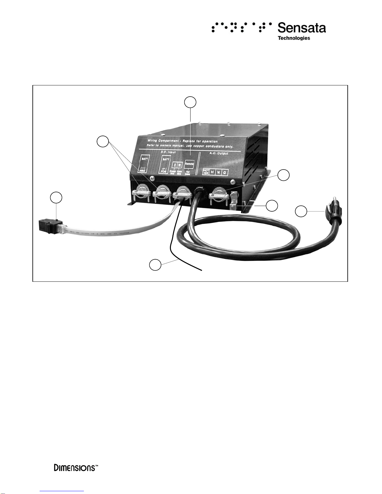
3.2.1 External Power Mode – “T” option: 120 VAC, 60 Hz external power can
be applied directly to the inverter when connecting the AC plug cord extending from the
inverter (available with the “T” option only) to an AC outlet. If external power is
available, the internal transfer switch cannot be defeated; it automatically turns the DC
to AC inverter OFF and activates the three-step battery charger “B3” if included
(available with 12W8 model only). At this time the loads attached to the inverter output
will operate directly from the external power line even if the inverter has been turned
OFF manually. The internal transfer relay automatically switches the inverter back to
“inverter power” mode in the absence of external power whenever the inverter was
previously set to ON.
3.2.2 Battery Charger – “B3” Option (12W8 model only): The three-step
battery charger feature requires the transfer switch “T” option to operate. External
power 120 VAC, 60 Hz is applied as explained in section 3.1.2 The internal transfer
switch automatically turns the DC to AC inverter OFF and turns the three-step built-in
battery charger ON. The battery charger cannot be defeated at this time and will engage
even if the inverter has been set OFF manually.
The 3-step charging process goes through the following stages: The bulk stage, here
the electrical current is returned to the batteries until a factory set voltage limit is
reached. The acceptance stage is then engaged immediately; the battery voltage is kept
constant while decreasing the charging current gradually up to the transition point or
when it reaches the pre-set timer limit. In the floating stage the batteries are recharged
at a very low current rate to prevent them from self-discharging. Finally the condition
stage is engaged every 20th complete battery charging cycles to ensure full restoration
of active materials in all the plates of the battery cells.
3.2.3 100 VAC, 60 Hz Output – “F3” Option: The inverter accepts and supplies
100 VAC, 60 Hz single-phase quasi-sine waveform output.
3.2.4 LED Remote Control/Status Panel – “R” Option: Remote control panel
“R” provides inverter status and allows remote ON/OFF operation. The remote control
panel has an “On/Off” switch and five LED indicator lights: External power, Inverter
power, Low battery, Overload and High temperature. The remote inverter control panel
is connected to the inverter module by a flat 8-conductor telephone type cable.
3.2.5 LED Remote Control/Status Panel – “R3” Option: Remote control
panel “R3” provides inverter status and allows remote ON/OFF operation. The “R3”
option has a single red wire extending from the inverter module, which must have
+12VDC for the inverter to operate (used as a master disconnect in recreation vehicles).
The remote control panel has an “On/Off” switch and five LED indicator lights: External
power, Inverter power, Low battery, Overload and High temperature. The remote
inverter control panel is connected to the inverter module by a flat 8-conductor
telephone type cable.

7 Form 122039
Inverter Physical Description
4.1 Inverter Module
Figure 1: Inverter physical description
Item # Description Function
1 Field wiring compartment faceplate. Covers the AC and DC wiring compartment. Remove
the faceplate to access the wiring compartment.
2 DC cable entry opening Allows the Red (+) and Black (-) cables to reach the
inverter’s DC input.
3 Remote panel cable connector Plug the 8-pin telephone connector to the remote
LED status panel.
4 Remote On/Off hookup wire - Violet
wire (Red wire for “R3” option)
T
urns the inverter “On/Off” when connected to
+12VDC.
5 AC input cord Connects to an external AC power source to
automatically power AC loads and activate the
battery charger (Option “B3”).
6 Bonding lug Connects to vehicle or chassis ground.
7 AC output hardwire strain relief Access for AC output wiring.
1
2
3
5
6
7
4

8 Form 122039
4.2 LED Remote Control/Status Panel
FIGURE 2: LED Remote Control/Status Panel
(a) “On/Off” Switch: Turns the inverter on or off.
(b) External power: Green LED that indicates the inverter is operating in external
power mode.
(c) Inverter power: Green LED that indicates the inverter is operating in inverter
power mode.
(d) Low Battery: Red LED that indicates a low battery voltage condition has
occurred.
(e) Overload: Red LED that indicates an overload condition has occurred.
(f) High temperature: Red LED that indicates an excessive internal temperature
condition has occurred.
c
b
a d
f
e

9 Form 122039
Installation
5.1 Tools for Installation:
Tools required for installation: Connectors (butt type and insulated), drill, Crimpers (for
insulated and non-insulated connectors), volt meter with probes, electrical tape, #2
Phillips screwdriver, wire cutters, wire strippers, cable ties, tape measure.
5.2 System Components:
Picture Model and Description Qty.
Inverter model: 12W6, 12W8
Options: B3, F3, R, R3 & T
1
141287-1 LED Remote Control/Status panel assembly.
1
611446-XX Remote inverter control panel flat cable.
XX = Cable length in feet.
1
5.3 Mounting the inverter:
5.3.1 Inverter Mounting
The inverter mounting location should provide adequate ventilation and
clearance to maintain room temperature during operation. At least 1/2 inch of
clearance is required on all sides.
•Locate a suitable, secure vertical or horizontal mounting surface as close to the
batteries as possible without being in the same airtight compartment.
•If mounting the inverter on a vertical surface, it is recommended that the front panel
be pointing down whenever possible.
•Locate the mounting holes on the chassis flanges and fasten them using ¼ inch
diameter screws to secure the inverter. See figure 3.
5.3.2 Chassis Bonding Lug: Connect the bonding lug located at the right side of
the inverter chassis to the earth grounding system using an 8-gauge copper wire.
5.3.3 Remote Control Panel Mounting: The remote control panel must be
mounted in a convenient, visible and accessible location. Connect the 8-pin flat phone
type cable connector coming from the inverter module to the receptacle on the rear of
the panel. See figure 4.

10 Form 122039
Figure 4 Control Panel Footprint
•All dimensions are in inches
2.2
4
Figure 3: Footprint
1
0.5
0.5
0.50.5
Case W
83.2
15
9

11 Form 122039
Inverter Wiring:
6.1 DC Wiring:
1It is recommended in all cases to use stranded copper wires.
2Use SGX cross-linked polyurethane insulation type that complies with the high
temperature insulation requirements (125°C.) of SAE J-1127 and vehicle
manufacturer requirements.
3Wire gauge recommendations are minimum. For higher temperature rated
applications inside engine spaces or large motor loads and other applications with
high surge currents use wire gauge 1 to 2 sizes larger than shown on table I.
4Keep the wire runs between battery and inverter as short as possible.
5Use Bussmann fuse type ANN-XXX and fuseblock # 3576 where XXX is the size of
the fuse.
6.1.1 Inverter Cable: This is the cable that runs from the inverter to the batteries.
Estimate the “inverter cable” length and locate your inverter model on table I, cross-
reference the wire gauge and fuse size.
Table I: Wire and Fusing Guide for 12VDC systems at 5% Voltage Drop at Full Output
Figure 5: Inverter cable assembly
6.1.2 Charge Cable: This is the cable that runs from the auxiliary battery(s) to the
vehicle alternator or OEM engine battery. Use 2-gauge cables and 250A fuse for small
OEM alternators and 1/0-gauge and 350A for heavy-duty alternators.
Inverter
Model Full Load
(Amps DC) Inverter to battery estimated cable length in feet
1’ – 10’ 11’ – 15’ 16’ – 20’
12W6 60 6-gauge, 150A fuse 4-gauge, 200A fuse 4-gauge, 200A fuse
12W8 80 6-gauge, 150A fuse 4-gauge, 200A fuse 2-gauge, 250A fuse
To inverter
DC input
To
batteries Fuse-holde
r
Black wire (-)
A
20 feet maximum
B
18” max.
Red wire (+)
A
B
Fuse B terminal: 5/16” RingA terminal:
3/8” Ring

12 Form 122039
6.2 Connecting the DC cables:
Damage to the inverter not covered under warranty will occur if correct
polarity is not observed when installing the DC input cables.
•Remove the inverter field-wiring compartment faceplate to access the DC input lugs.
•Unscrew the DC input lug POS (+) and NEG (-) screws.
•Remove the fuse from the fuseholder for cable installation.
•Remove 5/8 inch of insulation from the un-terminated ends of the red and black
cables.
•Insert the stripped end of the red wire into the DC input lug labeled POS (+) and the
stripped end of the black wire into the DC input lug labeled NEG (-). Tighten the
screws to 10 Ft. Lbs.
•Tighten the cover DC cable strain relief screws to 1 Ft. Lb.
•Connect the end of the short red cable to a POS (+) battery post.
•Connect the terminated end of the black cable (neg. return cable) directly to a
battery NEG (-) post (DO NOT connect to the chassis).
•Install the in-line fuse in the fuseholder that is within 18” of the positive post of the
battery bank (a one-time spark will occur when this final DC connection is made). To
determine the fuse size, refer to section 6.1.1.
6.2.1 Remote “On/Off” switch (customer supplied):
•Connect the 18-gauge violet wire to the load side of a fused “On/Off” switch.
•Connect a fused (5 amp recommended) +12VDC battery voltage to the line side of
the switch.
6.2.2 LED Remote Control/Status Panel (“R” or “R3” option):
•Plug one end of the flat remote signal cable into the panel receptacle, plug the other
end of the cable to the inverter mating receptacle.
•“R3” option: Connect the red wire to a circuit which has +12VDC battery voltage
when the master disconnect switch is not in the disconnect position.

13 Form 122039
Deep Cycle Battery Comments:
Do not use vehicle-starting batteries; deep discharge cycles typical with
inverter applications can shorten the life of this type of batteries.
•Install at least one auxiliary deep cycle battery to feed the inverter directly.
Depending on the application running time more batteries could be added if
necessary. The vehicle alternator will recharge the batteries.
•It is recommended to mount the battery bank close to the inverter. The maximum
recommended distance between the inverter and the battery bank is 20 feet.
•The battery compartment must be vapor-tight to the interior of the vehicle and
vented directly to the exterior.
•Install several vent-plugs within one inch of the top of the battery compartment to
allow for ventilation. Install a ventilation assembly as needed.
•Allow space around the battery and especially above the battery for inspection, and
maintenance purposes.
•The battery should not be able to move more than 1 inch in any direction.
6.3 AC Wiring:
6.3.1 General: Remove the inverter field-wiring compartment cover plate to access
the 120VAC*, 60Hz output terminal block and follow the color code connections:
•Hot (H) – Black Wire
•Neutral (N) – White Wire
•Ground (G) – Green Wire
6.3.2 AC Output: The 120 VAC*, 60 Hz current output produced by the inverter is
not ground fault circuit interrupt (GFCI) protected and requires the installation of remote
GFCI outlets. Not applicable with inverters having the “F3” option
•The GFCI outlets model recommended is Install GFCI outlets model Hubbell # GFR
5352XX (20A) or GFR 5252XX (15A).
•The 120VAC*, 60Hz output is presented behind the wiring compartment panel for
direct hardwire leads.
Do not connect another source of AC power directly to the output of the
inverter. This will result in damage to the inverter that is not covered under
warranty.
6.3.3 AC Input: Inverters having the charger “B3” option and/or the transfer switch
“T” option must plug the AC input cord into an external 120VAC* 60Hz power source.
* 100 VAC, 60 Hz input/output for inverters having the “F3” option

14 Form 122039
6.4 DC Wiring Diagram
Note: The violet wire connected to the load side of fused remote On/Off switch must
have +12VDC to operate.
Figure 6: DC wiring diagram
Flat Cable
LED Remote Control/Status Panel
Fuse
Red Wire
(
+
)
Black Wire
(
-
)
Charge Cable
Black (-)
Fuse
External Power
Inverter Power
Low battery
Overload
High temperature
ON
OFF
Inverter
To vehicle alternator or engine
battery
Charge Cable
Red (+)
12V Auxiliary Battery
Remote On/Off Switch
(Customer supplied)
Fuse
Violet wire
(Not available
with “R” or “ R3”)
Red wire
(“R3” option only)

15 Form 122039
6.5 AC Wiring Diagram
Figure 7: AC wiring diagram
H: Hot Wire – Black
N: Neutral Wire – White
G: Ground Wire - Green
•Install GFCI outlets model Hubbell # GFR 5352XX (20A) or GFR 5252XX (15A). (not applicable
with inverters having the “F3” option)
120VAC*, 60Hz Input
“T” Option
H N G
120 VAC*, 60 Hz Output
* 100VAC, 60Hz for inverters having the “F3” option

16 Form 122039
Operation and Troubleshooting
7.1 Operation
7.1.1 Turning the Inverter “ON”:
•To turn the inverter ON by switching on the remote On/Off switch.
•If the inverter has the “T” or “B3” options the green LED “Inverter Power” will come
on only in the event that there is no external power 120VAC, 60 Hz (100 VAC, 60 Hz
if “F3” option) applied, otherwise the green LED “External Power” LED will come on.
•Turn the inverter OFF if not in use. There is an approximated 1 to 2 amps DC draw
from the batteries at idle or no load.
7.2 Troubleshooting
Call or e-mail Customer Service Department for free consultation during business hours
(central time zone) at: 1-800-553-6418 or 1-651-653-7000; fax: 1-651-653-7600;
e-mail: [email protected]
•A TRUE RMS voltmeter is required for accurate AC output voltage readings on quasi-
sine inverters. Other voltmeters that use averaging circuitry will give incorrect
readings.
•Unplug all loads and connect a 100-watt light bulb to the inverter output. Observe
the LEDs light coming on at the Remote Control Panel then check the
troubleshooting table.
Table II
PROBLEM POSSIBLE CAUSES OR SOLUTIONS
No LEDs - No AC output power:
The Inverter is not connected to the
batteries; the battery voltage is below 9
volts DC or fault in the remote On/Off
circuit.
Check the in-line fuses for continuity. Make sure the DC
wires are clean and tight. Check the DC voltage at the
inverter DC input. Check or bypass the customer
supplied remote On/Off circuit.
Low battery– Red LED: Indicates that
the inverter has shut off due to a low
battery voltage condition.
Fault in the battery wiring, battery capacity and voltage
or the in-line fuse. This message will automatically clear
or the inverter will shut off.
Overload – Red LED: Indicates that
the inverter has shut off due to an
overload condition.
The inverter output wiring is shorted or loads exceed the
inverter rating. This message will automatically clear or
the inverter will shut off. Remove the short circuit or
excessive load from the output, and then switch the
inverter off then on. If the condition persists, call
Sensata Technologies.
High temperature – Red LED:
Indicates that the inverter has shut off
due to high internal temperature.
Verify that the inverter is in a vented compartment and
that the fan is not blocked. High ambient temperatures
combined with poor ventilation may also contribute to
the shut down. The unit will automatically turn back on
when it has cooled to 40°C (104°F).

17 Form 122039
Warranty
SHIPPING TERMS: F.O.B. St. Paul Minnesota. Freight prepaid and billed, subject to prior credit approval.
MINIMUM ORDER: $50.00 Net Price
LOSS OR DAMAGE: Loss or damage in transit are the responsibility of the carrier. Any claim should be filed with the
delivering transport company. Invoice, Bill of Lading and Delivery receipt with damage noted therein must accompany any
claims for freight damage. Claims for shortage and lost shipments must be made in writing to Sensata Technologies,
Power Controls White Bear, St. Paul, MN within 10 days of date of shipment. Claims not reported within this time frame
will not be honored.
PRICES: Prices are subject to change without notice. All orders are subject to acceptance at the factory. We reserve the
right to invoice prices in effect at time of shipment.
TERMS: Net 30 days with approved credit, credit card or C.O.D.
RETURN GOODS POLICY:
• No returned materials will be accepted without an accompanying Returned Materials Authorization Number (RMA) from
the factory.
• Credit will be issued for returned goods to the original purchaser within 60 days of purchase, provided the inverter is
returned to Sensata unused and not mounted. The amount of credit will be issued at Sensata’s discretion based on the
condition of the product.
• Customer must be in good standing with Sensata Technologies.
• Inverters that are discontinued, high-voltage (over 24vdc), special-order or used are excluded and will not be eligible for
credit. Non-inverter items such as cable assemblies, fuses and fuse holders, will not be eligible for credit
• Support components supplied by Sensata vendors will be covered under that manufacturer’s credit return policy.
• Customer pays return freight.
PLEASE SHIP AUTHORIZED RETURNS TO:
Sensata Technologies | Power Controls White Bear | 4467 White Bear Parkway | St. Paul, MN 55110
Return Freight Prepaid
LIMITED WARRANTY:
Sensata Technologies extends the following warranty to the original purchaser of those goods subject to the qualifications
indicated. Sensata warrants to the original purchaser for use that the goods or any component thereof manufactured by
Sensata will be free from defects in workmanship from the date of purchase for the period listed on the product label,
provided such goods are installed, maintained and used in accordance with Sensata and the original manufacturer’s
written instructions. Damages caused by the misuse, undue care or obvious wear through use will not be covered by this
warranty.
Components not manufactured by Sensata, but used within the assembly provided by Sensata, are subject to the
warranty period as specified by the individual manufacturer of said component, provided such goods are installed,
maintained and used in accordance with Sensata and the manufacturer’s written instructions.
Sensata’s sole liability and the Purchaser’s sole remedy for a failure of goods under this limited warranty and for any and
all claims arising out of the purchase and use of the goods, shall be limited to the repair or replacement of the goods that
do not conform to this warranty.
To obtain repair or replacement service under the limited warranty, the purchaser must contact the factory for a Return
Material Authorization (RMA). Once obtained, send the Return Material Authorization Number along with the defective
part or goods to:
Sensata Technologies, Power Controls White Bear, 4467 White Bear Parkway, St. Paul, MN 55110. Return Freight Prepaid.
THERE ARE NO EXPRESS WARRANTIES COVERING THESE GOODS OTHER THAN AS SET FORTH ABOVE. THE IMPLIED
WARRANTIES OF MERCHANTABILITY AND FITNESS FOR A PARTICULAR PURPOSE ARE LIMITED IN DURATION TO ONE
YEAR FROM DATE OF PURCHASE.
SENSATA TECHNOLOGIES ASSUMES NO LIABILITY IN CONNECTION WITH THE INSTALLATION OR USE OF THE
PRODUCT, EXCEPT AS STATED IN THIS LIMITED WARRANTY. SENSATA TECHNOLOGIES WILL IN NO EVENT BE LIABLE
FOR INCIDENTAL OR CONSEQUENTIAL DAMAGES.
WARNING:
LIMITATIONS ON USE: DIMENSIONS®brand products are not intended for use in connection with Life
Support Systems and for Avionic use. Sensata Technologies makes no warranty or representation in connection with their
products for such uses.
This manual suits for next models
1
Table of contents
Other m-Dimension Inverter manuals