Plus M-125 User manual

COPY BOARD
M-125
SERVICE MANUAL

1. COMPLIANCE OF SAFE REPAIR ............................... 1
1-1. Cautions during Product Displacement ..................... 1
1-2. Cautions during Disassembling and Assembling....... 1
2. SPECIFICATIONS ........................................................ 2
2-1. Product Specifications ............................................... 2
2-2. Location of Parts and Controls .................................. 3
2-3. Operation Panel of Main Unit.....................................5
2-4. Error Display .............................................................. 6
2-5. Test and Adjustment Functions ..................................7
3. SOFTWARE PLUS TOOLBOX .................................... 8
3-1. Installation of the Software ........................................ 8
4. TROUBLE SHOOTING................................................. 11
5. DISASSEMBLY AND ASSEMBLY ............................... 12
5-1. Tools Required ........................................................... 12
5-2. Caution ...................................................................... 12
5-3. Disassembly and Assembly Procedures.................... 12
5-4. Disassembly and Assembly .......................................13
6. CONNECTION TO THE SET........................................ 19
6-1. Connecting the main unit and printer......................... 19
6-2. Mounting the AC adapter box to the printer table ...... 20
6-3. Wiring the cables in the cable cover .......................... 21
CONTENTS
7. SETTING THE TIME..................................................... 23
8. FUNCTION SETTING ................................................... 25
8-1. Basic Setting Operations ........................................... 25
8-2. Table of Function Numbers, Selected Modes
and Lamp Statuses .................................................... 26
8-3. Factory Defaults......................................................... 27
8-4. Updating the Internal Program of a Main Set ............ 27
9. ADJUSTMENT.............................................................. 29
9-1. CCD Adjustment ........................................................ 29
9-2. Calibration.................................................................. 34
9-3. TensionAdjustment of Timing Belt .............................35
10. Cable and Cable connection .................................... 36
11. PARTS LIST............................................................... 37
1. Overall configuration ..................................................... 38
2. Frame Cover Section .................................................... 39
3. Sheet Frame Section .................................................... 41
4. Board Frame Section .................................................... 43
5. Accessories Section ...................................................... 44
6. Carton & Packing .......................................................... 46
7. M-11-T/M-12-T .............................................................. 48
8. Screws & Washers........................................................ 50
12. REVISION HISTORY .................................................. 51

1
1. COMPLIANCE OF SAFE REPAIR
Be sure to read this Service Manual before providing services. In the PLUS Copyboard, full consideration is
taken to ensure the safety for a fire, electric shock, injury, harmful radiation, and substance. Therefore, observe
the notice described in this Service Manual so that the safety is kept when providing services. Moreover, be sure
to observe the notice described in the User’s Manual.
Pay attention to the following during service inspection.
1-1. Cautions during Product Displacement
• It is necessary to remove the products when making the service of products put on the wall. At that time, hold
the products by two or more persons to prevent the products from dropping or a person from falling down.
1-2. Cautions during Disassembling and Assembling
1. This equipment contains parts under high voltage. When doing repairs, make sure that power plug is pulled
out to insure safety.
2. Make sure that parts, screws and wiring, etc. are returned to their original positions. Tube, tape and other
insulation materials have been used for safety reasons. The internal wiring has been designed to avoid
direct contact with hot parts or parts under high voltage when using clamps or other tools.
3. The parts used in this device have special safety features such as flame-resistance and anti-voltage proper-
ties. When replacing parts, always use parts supplied from the factory.
4. After finishing operations make sure that all parts and wires have been returned to their original position and
that there has been no deterioration of the area around the portion that was worked on.
5. Pay attention to static electricity when handling electronic parts on a board.

2
2. SPECIFICATIONS
2-1. Product Specifications
BOARD TYPE (Model name)
Form Installation method
External dimensions
(T-shaped legs*1)
Main unit weight
T-shaped legs weight
Board Panel Size
Effective reading size
Number of Pages
Paging
Drive method
Reading method
Reading illumination
Light source
Reading resolution
Reading time
Memory Type
Compatible FAT types
File format
Interface
Control panel Control buttons
LED Indicators
Display
Added functions
Clock
PC connection
Power supply AC power adapter
Operating Temperature
conditions Humidity
Recording Printer interface
section
Miscellaneous Ruled lines
Miscellaneous
5-surface (M-125)
Self-standing (T-shaped legs), or wall mounting
W1470 ✕D700 ✕H1970 (Max) mm
35 kg (excluding printer)
9.6 kg
H920 ✕W1300 mm
H900 ✕W1280 mm
5 (4 sheet surfaces + 1 screen surface)
Wind-up type
Sheet movement
CCD sensor reduction optical system
RGB LED
Main scanning direction (vertical sheet surface) 2.4 dots/mm (60 dpi or equivalent)
Sub scanning direction (horizontal sheet surface) 2.4 dots/mm (60 dpi or equivalent)
Black & white: approx. 15 s
Color: approx. 23 s
USB Flash memory*2
FAT 12, 16, 32
PNG, JPEG and PDF format
USB1.1 or USB2.0 full-speed mode*3
ON/Standby, + , -, Print, Save, Reprint, Color, Density, (Page Change), Screen
Density, Color, Page LEDs
7-Segment (Page, Error # ),
Used for the timestamp and for file dating properties
(Includes backup battery for when there is a loss of power)
Transfer of sheet surface image data via USB (TWAIN supported)
Input : AC100 - 240V/50 - 60 Hz, Max 1.5A
Output : DC24 V, 2.71 A
10 - 35°C
30 - 85% (No condensation)
USB1.1 or USB2.0 full-speed mode*3compliant printers are supported
50 mm cross-ruled squares
Special markers (black, red, blue,and green)
Remarks
*1: The height is adjustable at 1770, 1870 and 1970 mm.
*2: A USB memory is not included in the package.
*3: Does not correspond with, High-speed mode.
•
Please note that for quality improvement purposes, specifications and design subject to change without prior notice.
•This machine contains eParts of the eSOL, Co.,Ltd.
•Depending on the product, the printer and T-shaped legs (stand) will be available separately.

3
Frame cover
Main unit
Sheet
Dedicated markers are used on the sheet to
draw diagrams and to write.
Control panel
Pen tray
Stand*1
This stand supports the copyboard.
Effective Reading Size
The area that can be copied is
the gray area of the diagram.
Note:
•
It might not be possible to print
or copy when storing to USB
memory or personal computer
any portions that are drawn
outside of this range.
Effective reading size
approx. 10 mm
approx. 10 mmapprox. 10 mm
approx. 10 mm
Printer table
The printer* is placed here.
AC adapter box
Store the AC power adapters of the
copyboard and printer here.
SPECIFICATIONS
2-2. Location of Parts and Controls
Front panel of main unit

4
SPECIFICATIONS
Back panel of main unit
PRINTER
PC
DC-24V
DC input connector
Connect the DC side of an AC power adapter to the
DC input terminal.
(Connect only the AC power adapter exclusively
used for this set to this terminal.)
PC-dedicated USB port (Type B)
Printer connector (USB portType A)
Connect this with the USB connector of the printer.
(The printer connector is dedicated for use with a
printer; use it only with a printer.)
* A stand may be available optionally.
Caster
Stabilizer
Locking and unlocking the caster of a stand*
After installation, fix the caster using a stopper.Remove a stabilizer
during moving the copyboard and unlock the stopper of a caster.To fix
a stopper,
push the lower position of the stopper.
To unlock a stopper, push the upper position of it.
This function is used when read operation is started
from the personal computer side and image data is
directly transferred to the personal computer or when
the operating environment of this unit is set from the
personal computer side. Before using this function,
install the driver and software in the supplied CD-ROM.
The connector is located on the bottom
surface of the copyboard.
The diagram view is seen from the bottom.
Cancellation
Fixation

5
Number of Copies
Reprint Screen
Density
1 ON/Standby button
Turns the copyboard’s power on and off (standby mode).
The function settings can be made by pressing the
Density and ON/Standby buttons simultaneously.
When pressing a button, please press the center area
(i.e., the round and protruding portion). The button may
not work if it is pressed on a corner.
3 Print button
Moves a one-screen portion of sheet and reads it, then
prints the number of copies displayed in the display
window.
4 + / - buttons (Number of copies)
Pressing the + button or the - button sets the number of
copies to be printed (to a maximum of 20 sheets).The
number of copies appears in the display window.
5 Save button (USB memory storage)
Moves a one-screen portion of sheet and reads it, then
stores the data on a USB memory.
6 Memory port (USB portType A)
Saves in commercially-available USB memory images
that have been read by the copyboard.
7 Reprint button
Prints the previously printed sheet surface one more time.
(The sheet does not move.)
The number of copies can be changed, but the density
and the color/monochrome selection cannot be changed.
8 Density button
Selects the copying density, either “standard”or “dark”.
This function will be effective at time of printing, USB
memory storage, and personal computer storage.
Density mode lamp
The density mode indicator lights green when “dark” is
selected.
9 Color button
Selects whether to print (or store in memory) in “color” or
“black & white”.
Color mode lamp
The color mode indicator lights green when “color” is
selected.
*
When a black & white printer is connected, the printout
will be in black & white even when “Color” is selected.
10 Page change / buttons
Use these to switch pages.
• Each press of the page change button moves the
page indicator one step in the sequence o
f 1 2 3
4 making it flash, and scrolls the copyboard to the
specified page.
• Each press of the page change button moves the
page indicator one step in the sequence of S
4 3
2 1
making it flash, and scrolls the copyboard to
the specified page.
Note:
Scrolling to the screen (S page) is not possible with
the page change button.
Page indicators
The indicator for the currently displayed page lights
(green).
When scrolling, the indicator for the specified page
flashes while the page is scrolling, then stops flashing,
remaining lit, once scrolling stops.
11 Screen button
When pressed, the sheet scrolls to the screen (the S page).
2 Display window
This 7-segment LED displays the number of copies to be
printed, the USB memory storage operating condition,
and error information.
Note:
If the Erase Reminder function has been set, the sheet
moves to the surface that has not yet been erased before
the power turns off *1.
*1 Depending on the usage method, the Erase
Reminder function may not operate properly.
Color
Page
ON/
Standby
MEMORY
4
5
10
11
6
9
1
8
3
2
7
M-125
Print
Save
SPECIFICATIONS
2-3. Operation Panel of Main Unit

6
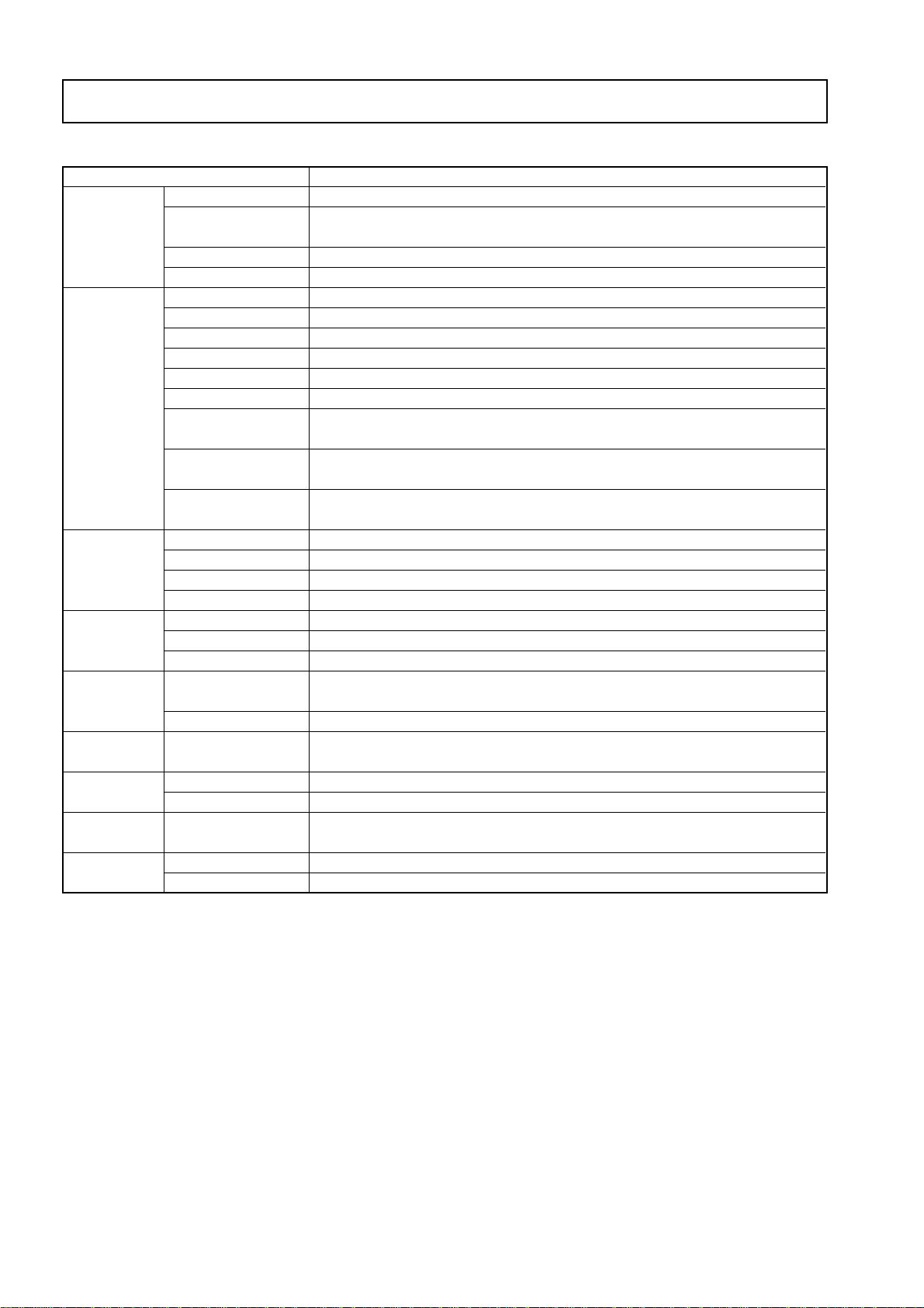
Error display number
Printer not connected
No printing paper
Printer problem
USB Memory
not recognized
USB Memory storage
problem
Reading problem
System error
Page detection error
Security protection
Restrict color mode
USB memory not
connected
When the “USB” letter is flowing...
Warning that disconnection of
USB memory
has been forgotten
No Calibration data
USB Memory is full
An unsupported
printer is connected
Time setting error
Problem and Solution
•Is the printer cable connected?
•
Is power being supplied to the printer?
•
When the printer uses an AC power adapter,
is the cable disconnected somewhere?
•Has paper been set in the printer?
•
Is the printer error indicator flashing (or lit)?
•Is the USB memory unformatted.
•Is a USB memory that is not supported
by the copyboard being used?
•
Is the USB memory device plugged in fully?
•Is the USB memory damaged?
• An error occurred during USB memory
storage.
•There is a lighting fault of the reading
light source, or a read signal error.
•There is a memory or internal fault.
•The pages are not being properly
detected.
•You have attempted to use a function
disabled by the security settings.
•Setting for disabling printing/storing in the
color mode.
•USB memory device is not plugged into
the main unit.
• Did you press the ON/Standby button
while the USB memory device was
plugged into the main unit?
•This is the state in which calibration data
is not written.
• There is no available space.
• A printer that is not supported by the
copyboard has been connected.
• An error has arisen when setting the time.
•Connect the printer properly and
switch on the printer power.
•Turn the power of the printer off and
then on again, and load the printer
with A4 paper.
•Read the printer instruction manual.
•This unit supports the FAT and FAT 32
formats. Perform the formatting with
the personal computer.
•Please see our home page for informa-
tion about USB memories that can be
used with the copyboard.
( http://www.plus-vision.com )
• Please check the operation with a
personal computer.
• Please perform USB memory storage
again.
• Do not insert or remove the USB
memory during processing.
• Unplug the power plug from the power
outlet and then plug it in again.
• Unplug the power plug from the power
outlet and then plug it in again.
• Unplug the power plug from the power
outlet and then plug it in again.
•The settings can be changed using
the exclusive software. For details,
contact your nearby PLUS Vision
sales office, dealer or store.
•Can be changed in the copyboard’s
“Function Settings”.
• Plug the USB memory device into the
USB port.
•AUSB memory device is plugged into
the main unit. When the USB memory
device is disconnected, the power will
be switched off and the unit will enter
the standby mode.
•Perform calibration.
• Please delete unnecessary data using a
personal computer.
• Press the ON/Standby button and
switch off the power. When a record is
required, switch on the power and
save to USB memory.
• When the ON/Standby button is
pressed, the display switches to “c1”.
Start the setting over from the year.
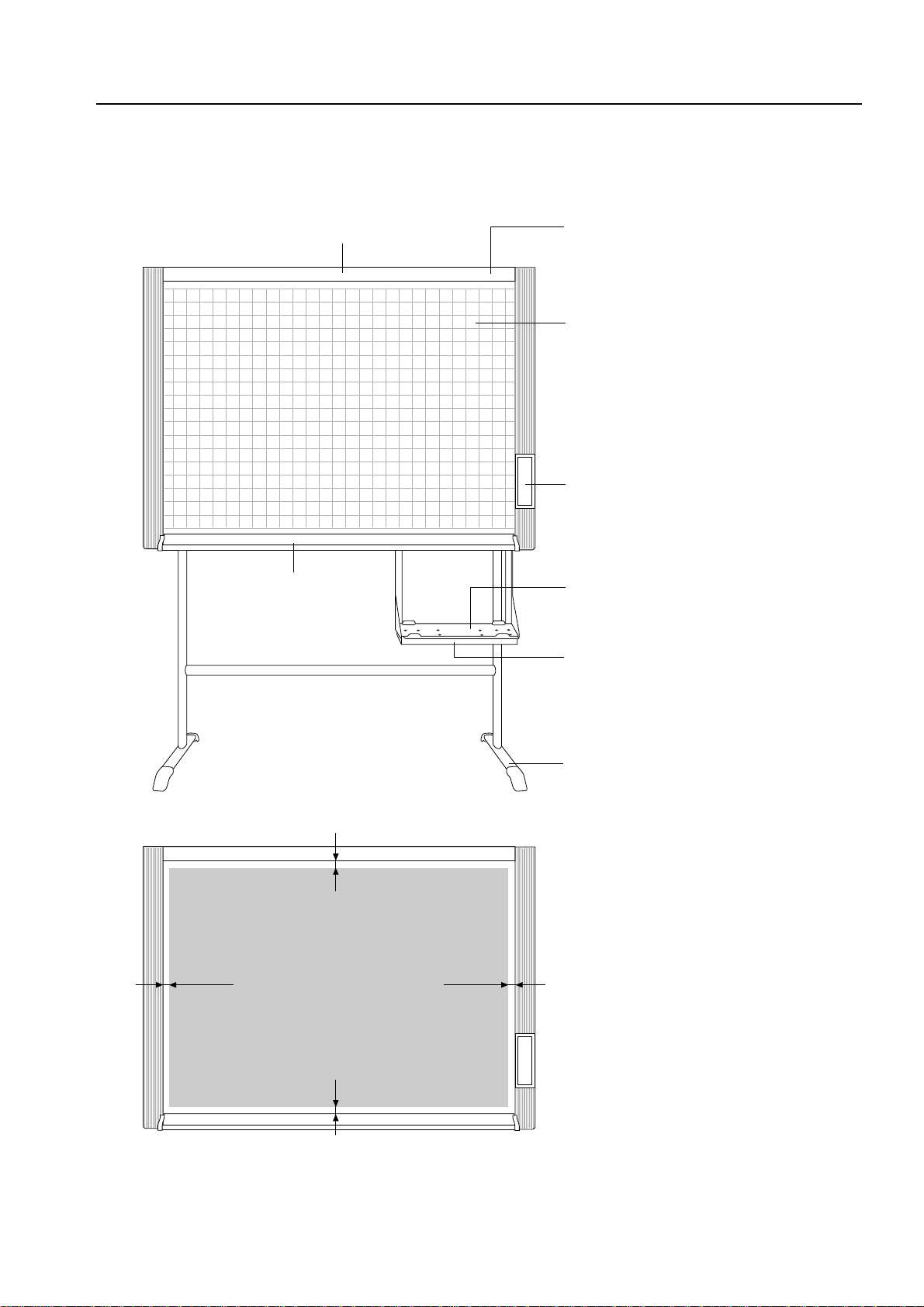
SPECIFICATIONS
2-4. Error Display
If any of the following flashing indications appear in the display window
of the control panel, please check the matters described below.
M-125
Number of Copies

7
SPECIFICATIONS
2-5. Test and Adjustment Functions
The specifications for inspection and the calibration program are described below.
1) Seven-segment display specifications.
2) To shift to the test/adjustment mode, press the “+” and “-” buttons simultaneously in the sleep mode and
then press the Power button.
The numeric LED display is <AP>.
3) Shift to each test mode by the button operation below.
1 Printer test mode <4. SPC> (*1)
A test print is made from the printer connected to a copy board when you press the Feed/Stop button
and then the print button during button operation. (During connection of a color ink jet printer, press the
color button, select the color mode, and then press the print button.)
2 Calibration mode start <2. SPC> (*1)
Calibration is executed when you press the Print button during button operation.
3 CCD adjustment mode <6. SPC) (*1)
An RGB adjustment mode sequence is performed (LED lights in red during CCD adjustment) when you
press the additional Reprint button during button operation.
4 Program version display & Internal Information write. <1.SPC>
The major version of a program is displayed when you press the “-” button once.
The minor version of a program is displayed when you press the “-” button second.
5 Five-plane extended test mode <8. SPC>
The current state is shifted to the five-plane extended test mode when you press the screen button
during button operation.
The current state is shifted to the solenoid forced ON mode when you press the “+” button. In this case,
the sheet latch is freed. (Free) <8.0>
The current state is shifted to the solenoid forced OFF mode when you press the “-” button. In this case,
the sheet latch is locked. (Lock) <8.1>
Initial processing is performed when you press the color button. <8.7>
Initial processing: Moves to page 1 and sets page number 1.
* 1. SPC indicates the state in which no LEDs light.
Indicates an error occurring in the test mode. (Lights : Error)
Progress number in the test mode
Indicates the whole test mode.(Lights :Test mode)
A signal of a test mode.

8
3. SOFTWARE PLUS TOOLBOX
3-1. Installation of the Software
When “Install Software” on the included CD-ROM’s menu is clicked, the “PLUS TOOLBOX”, TWAIN driver and
USB driver are installed.
Check Prior to Installation
1. Check whether your personal computer satisfies the operating environment.
2. Check that your personal computer is not currently connected to this machine via USB.
3. At the time of installation, install withAdministrator rights (i.e., a user having administrator rights) for Windows
2000, or with a Computer Administrator rights (account) for Windows XP/Vista.
4. Close all other applications that are running.
Installation of the PLUS TOOLBOX
1Insert the supplied CD-ROM into the CD-ROM drive
of the personal computer.
The menu screen will be displayed automatically.
If the menu screen is not displayed automatically,
double click CD-ROM icon and double click
“autorun.exe”.
2Click “Installation of Software”.
The installer will start.
3Follow the instructions of the installer and start the
installation.
The PLUS TOOLBOX, the TWAIN driver, the USB
driver will be installed at the same time.
M-12setuplauncher
Thankyouforyourpurchasingof
PLUSproduct
TheCD-ROMcontainsfollowing
softwareandanelectronicmanual
*Installation
1)PLUSTOOLBOX
2)TWAINDriver
3)USBDriver
*M-12SeriesUsersManual
(PDFformat)
*PLUSTOOLBOXSoftwareManual
Welcome
InstalationofSoftware
User'sManual
AcrobatReader
SoftwareManual
BrowseCD
Copyright&Usage
?
PLUS
PLUSTOOLBOX-InstallShieldWizard
WelcometotheInstallShieldWizardforPLUS
TOOLBOX
TheInstallShield(R)WizardwillinstallPLUSTOOLBOXonyour
computer,Tocontinue,diskNext.
Cancel
Next
<Back>
WARNING:Thisprogramisprotectedbycopyrightlaw
andinternationaltreaties.

9
SOFTWARE PLUS TOOLBOX
Note:
*The Windows Security dialog box will be displayed
with Windows Vista.
Select “Install this driver software (I)”.
*When using Windows Vista, each time the installer is
started, the User Account Control dialog box is dis-
played.
Select “Continue” and continue with the installation.
4Click “Finish”.
The “Installer Information Dialog Box” will be displayed.
Click “Yes (Y)” and restart the personal computer.
When this software is installed in the personal com-
puter for the first time, continue to make the following
connections and operations.
■Installing the USB Driver
The USB driver is installed in the computer with the installer, but this does not complete association with the USB
port. In order to use PLUS TOOLBOX, install using the procedure described below with the copyboard con-
nected.
Preparation 1. Press the ON/Standby button of the Copyboard to turn on the power.
2. Use a USB cable to connect the USB port of the personal computer with the PC dedicated
USB port of the Copyboard.
The New Hardware Search Wizard will be displayed.
Install according to the New Hardware Search Wizard.
WindowsSecurity
Wouldyouliketoinstallthisdevicesoftware?
Name:JungoJungo
Publisher:JungoLTD
Always trust software from "Jungo LTD".
You should only install driver software from publishers you trust.How can I
decide which device software is safe to install?
Don't Install
Install
WindowsSecurity
Windowscan'tverifythepublisherofthisdriversoftware
Don'tinstallthisdriversoftware
Youshouldcheckyoumanufacturer'swebsiteforupdateddriver
softwareforyourdevice.
Installthisdriversoftwareanyway
Onlyinstalldriversoftwareobtainedfromyourmanufacturer'swebsiteor
disc,Unsignedsoftwarefromothersourcesmayharmyourcomputeror
stealinformation.
Seedetails
PLUSTOOLBOX-InstallShieldWizard
Cancel
Finish
<Back>
InstallShieldWizardCompleted
TheInstallShieldWizardhassuccessfullyinstalled
PLUSTOOLBOX,ClickFinishtoexitthewizard.
PLUSTOOLNOXInstallerInformation
Youmustrestartyoursystemfortheconfiguration
changesmadetoPLUSTOOLBOXtotakeeffect.
ClickYestorestartnoworNoifyouplantorestart
later.
No
Yes

10
1Select “Install Software Automatically (Recom-
mended) (T)” and click “Next (N)” (when using Win-
dows XP).
Start the installation of the USB driver.
Note:
*Installation will be completed automatically with
Windows 2000/Windows Vista.
SOFTWARE PLUS TOOLBOX
2Click “Finish”.
This software can now be used.
Uninstallation of the PLUS TOOLBOX
1Selecting [Start] →→
→→
→[Control Panel] will display the Control Panel screen.
Check that your personal computer and the Copyboard are not currently connected by USB.
2Double click “Add or Remove Programs or Applications” (this will differ depending on the OS) to
display the “Add or Remove Programs Properties” screen.
3Select PLUS TOOLBOX from among the list displayed and click [Change / Remove] to display the Add
or Remove wizard screen.
4Selecting the [Remove] radio button of the wizard and clicking [Next] will start the uninstallation.
Note:
*“Add or Remove Programs” will be displayed for Windows XP/Vista.
*When using Windows Vista, each time the uninstaller is started, the User Account Control dialog box is
displayed.
Select “Continue” and continue with the uninstallation.
FoundNewHardwareWizard
IfyourhardwarecamewithaninstallationCD
orfloppydisk,insertitnow.
Installthesoftwareautomatically[Recommended]
Installfromalistorspecificlocation[Advanced]
ClickNexttocontinue.
Cancel
Next>
<Back>
Thiswizardhelpsyouinstallsoftwarefor:
PLUSCopyboard
Whatdoyouwantthewizardtodo?
FoundNewHardwareWizard
Thewizardhasfinishedinstallingthesoftwarefor:
PLUSCopyboard
[ClickFinishtoclosethewizard
CompletingtheFoundNew
HardwareWizard
Cancel
Finish
<Back>

11
4. TROUBLE SHOOTING
By checking operations normal usage time, it is possible to carry out judgments on malfunction to a certain extent. Carry out the following
checks before disassembling the equipment.
1. Press the ON/Standby button and turn on the power.
Is the power turned on?
No • The power cord is disconnected from the wall outlet.
• The AC Adapter is defective.
• The Main Board Assy is defective.
• The Switch Box Unit is defective.
• The connector of the Switch Harness is disconnected.
Yes
Does the error display appear?
Yes The error display (E4) appears.
• The connectors of the CCD Harness Assy is disconnected.
• The CCD Unit is out of adjustment.
• The CCD Unit is defective.
• The Main Board Assy is defective.
The error display appears.
• The Main Board Assy is defective.
The error display (E.E.) appears.
• Damaged Calibration data. Start Calibration.
No
2. Press the Page change button.
Does the sheet operate normally?
No The error display (E6) appears.
• The connectors of the Solenoid Harness are disconnected.
• The connectors of the Sensor Harness are disconnected.
• The SolenoidAssy is defective.
• The Sensor Assy is defective.
Yes
3. Press the Print button (when a printer is used).
Does the error display (E1) appear?
Yes Printer failure
• The printer is defective. (See the Instruction Manual of a printer.)
• The power of a printer is not turned on.
• The paper of a printer is exhausted.
• The printer is not connected.
• The Main Board Assy is defective.
No
Is the object written in the board printed normally?
No A black line is put in printing.
• Out-of-adjustment of CCD Unit: Slight (It is improved by calibration.)
• Out-of-adjustment of CCD Unit: Severe (Perform the CCD adjustment again.)
• Dust adheres to the mirror of the board body.
Printing becomes blurred.
• The marker (written character) becomes blurred
• The ink (toner) of a printer is exhausted.
A specific color is not printed or the printed color is improper (when a color printer is used).
• The ink of a printer is exhausted.
• The ink cartridge of a printer is defective.
Yes
4. Press the Save button (when a USB memory is used).
Do the error displays (E2 and E3) appear?
Yes Error display: E2 is displayed.
• A USB memory is not formatted.
• An incompatible USB memory is used.
• A USB memory is defective.
Error display: E3 is displayed.
• Memory storage error: Repeat storage again.
• The Main Board Assy is defective.
No
Is the object written in the board stored normally?
No A black line is put in a picture.
• Out-of-adjustment of CCD Unit: Slight (It is improved by calibration. See section 9-2.)
• Out-of-adjustment of CCD Unit: Severe (Perform the CCD adjustment again. See section 9-1.)
• Dust adheres to the mirror of the board body.
A picture becomes blurred.
• Out-of-installation of CCD Unit. (It is improved by calibration.)
• The marker (written character) becomes blurred.
Yes
Normal operation

12
5. DISASSEMBLY AND ASSEMBLY
5-1. Tools Required
• Phillips screwdriver (+) No. 2
• Cutting pliers
• Locking tie (Cable tie)
5-2.Caution
• See “1. Compliance of Safety Repair and Safety Inspection” before disassembling and assembling.
• Put on gloves so that you do not cut your hand at the sharp edge of a frame during disassembly and assem-
bly.
• See “10. Wiring Diagram” and “11. Parts List” for the parts name or wiring.
• The point especially requiring attention when handling parts or performing disassembly and assembly con-
tains a caution. Be sure to follow this caution.
5-3. Disassembly and Assembly Procedures
START
LED Unit
Back Panel
Main Board Assy
Frame Cover Unit Switch Box Unit
Sheet Frame Unit Sheet Motor Unit
Pulley
Solenoid Assy
Sensor Board Unit
White Sheet

13
DISASSEMBLY AND ASSEMBLY
2) Remove the Main Board Assy. (See Figs. 3 and 4.)
1. Disconnect the connectors connected to the Main
Board Assy shown in Fig. 3.
2. Remove the “S-3” screws shown in Fig. 4 and then
remove the Main Board Assy.
Note:
Be careful when the screws are removed and installed.
It is recommended to use a stubby driver. (No.2 Phillips
screwdriver length : 45 mm)
*The battery installed in the Main Board Assy can be
used without any functional problem for ten years or
more.
*When disconnecting the connector of the Main Board
Assy, identify (for example, mark) it in advance because
the connector size is located in the same place.
*For a new Main Board Assy of M-125 type, volume
control R82 is not installed because of automatic ad-
justment. (Calibration is required)
5-4.Disassembly and Assembly
This section describes one example of disassembly and assembly procedures. For the actual operation,
disassemble and assemble the required parts with reference to “5-3. Disassembly andAssembly Procedures”.
1) Remove the Back Panel. (See Figs. 1 and 2.)
1. Remove the “S-7” screws shown in Fig. 1 and then remove the Back Panel Corner.
2. Remove the Back Panel as shown in Fig. 2.
Fig. 1
Fig. 2
Fig. 4
Fig. 3
S-7
Back Panel Corner
Back Panel
CN10
CN2
CN9
CN8 CN5
CN12
CN1
CN3
CN6
CN7
CN4
MainBoardAssy
S-3
Main Board Assy

14
S-3
S-4
S-3
CCD Unit
CCD Harness
DISASSEMBLY AND ASSEMBLY
3) Remove the CCD Unit. (See Fig. 5.)
1. Remove the “S-3” screws shown in Fig. 5.
2. Remove the “S-4” screws shown in Fig. 5 and then
remove the CCD Unit.
Note:
The CCD Unit requires adjustment when it is replaced
and removed. (See 9. Adjustment.)
Fig. 5
Fig. 6
4) Remove the Frame Cover Section. (See Fig. 6.)
1. Remove the “S-2” and “S-9” screws shown in Fig. 6.
2. Disconnect the Switch Harness of the Main Board Assy from the square hole of the Sheet Frame.
S-9
S-9 S-2
S-2
S-2 S-2
Cap L
Cap R
Cap R
Cap L
Switch Harness
Back Side

15
DISASSEMBLY AND ASSEMBLY
Fig. 7 Fig. 8
5) Remove the Switch Box Unit. (See Fig. 7.)
1. Remove the “S-8” and “S-10” screws shown in Fig. 7.
2. Remove the “S-5” screws shown in Fig. 7 and then remove the Switch Box Unit.
Notes:
· Be careful not to mistake the hole through which the Switch Harness is passed. (See Fig. 8.)
· Pay attention to a kind of screw.
S-8
S-10
Switch Box Unit
[Front Side] [Other Side]
Switch Harness
Fig. 9
6) Disassemble the Frame Cover Section. (See Fig. 9.)
Remove the “S-1” and “S-2”, “S-6”, “S-20” screws shown in Fig. 9 and disassemble the Frame Cover.
S-2
S-1 S-2
S-20
S-20
S-1
S-1
S-6
S-6
S-2
S-2
S-1
Frame Cover Upper
Frame Cover Side L
Frame Cover Side R
Cover Plate
Cover Plate
Cover Plate
Cover Plate
Cover L
Cover R
Cover
Upper Cover Plate
Upper Cover Plate

16
DISASSEMBLY AND ASSEMBLY
Fig. 10
Fig. 11
7) Remove the Sheet Frame Unit. (See Figs. 10 and 11.)
1. Remove the “S-1” screws shown in Fig. 10.
2. As shown in Figure 11, loosen the “S-11” (two)
screws to the frame surface and remove the Sheet
Frame Unit.
Notes:
·The Sheet Frame Unit is caught on a hook as shown
in the portion A of Fig. 10.
*Remove the Motor, the Sensor Board and the Sole-
noid earlier when the Sheet frame Unit is removed.
S-1
S-1
Portion A
Sheet Frame Unit
S-11
Sheet Frame Unit
Frame side
S-11
Fig. 12
8) Remove the Sheet Motor Unit. (See Fig. 12.)
1. Remove the “S-12” screws shown in Fig. 12 and
then remove the Sheet Motor Unit.
Note:
·Remove the Motor harness earlier when remove the
Sheet Motor Unit.
·Adjust the tension of a Timing Belt when installing
the Sheet Motor Unit. (See Fig. 9-3. Adjustment)
S-12
S-12
Motor Harness
Motor Rubber
Sheet Motor Unit
* The operation in Figures 11 to 14 is performed with
the Sheet Frame Unit put upside down.

17
DISASSEMBLY AND ASSEMBLY
Fig. 15
Fig. 13
Fig. 14
9) Remove the Pulley, Belt. (See Fig. 13.)
1. Remove the “S-13” screws shown in Fig. 13 and
then remove the Gear Plate.
2. Remove the “S-18” E-rings shown in Fig. 13 and
then remove the Pulley, Belt.
S-13
S-18
S-13
Gear Plate
Belt
Pulley
Heyless Bush
Sheet Bottom
Sheet Roller
bearing
S-19
S-17
S-19
Solenoid Unit Solenoid Assy
Stopper Stopper
Spring
Stopper
Joint Assy
S-5
Sensor Board Unit
10) Remove the Solenoid Assy. (See Fig. 14.)
1. Remove the “S-19” screws shown in Fig. 14 and
then remove the Solenoid Assy.
2. Remove the “S-17” E-rings shown in Fig. 14 and
then remove the Stopper.
*Replace it in units of “Solenoid Unit” when replac-
ing the Solenoid Assy.
11) Remove the Sensor Board Unit. (See Fig. 15.)
1. Remove the “S-5” screws shown in figure and then
remove the Sensor Board Unit.
Note:
Be careful not to damage the White Sheet when the
Sensor Board Unit removed and installed.

18 Fig. 17
13) Remove the LED Unit. (See Fig. 17.)
1. Remove the LED Harness as shown in Fig. 17.
2. Remove the “S-3” screws as shown in Fig. 17.
3. Remove the LED Unit as shown in Fig. 17.
Note:
Use the parts assembled in a factory during replace-
ment of an LED unit.
*Calibration is required after replaced.
LED Unit
LEDHarness
S-3
S-3
Fig. 16
S-5
S-5
S-5
S-7
S-5
S-7
S-5
S-5
S-15
A
A
A
A
White Sheet
Angle
Angle
Sheet
Bearing
Lever Plate
B Portion
A Portion
Sheet Guide
Sheet Guide
Sheet Frame L Guide
12) Remove the White Sheet. (See Fige.16.)
1. As shown in portion A in the auxiliary drawing of Figure 16, remove the “S-7” screws and then remove the
two Sheet Guides (at the top and bottom).
2. As shown in portion A in the auxiliary drawing of Figure 16, remove the “S-5” screws and then remove the
two Sheet Frame L Guides (at the top and bottom).
3. Remove the “S-5” screws shown in Fig. 16 and then remove the Angle.
4. Loosen the “S-15” screw shown in portion B in the auxiliary drawing of Figure 16 as far as it will go.
5. As shown in portion B in the auxiliary drawing of Figure 16, loosen the Lever Plate and push the top of the
Sheet Bearing upward.
6. As shown in Figure 16, remove the bottom of the White Sheet and then remove the top of it.
7. As shown in Figure 16, wind the White Sheet.
Note:
Be careful not to damage or fold it when handling the White Sheet.
Table of contents
Other Plus Office Equipment manuals
Popular Office Equipment manuals by other brands

silen
silen CBX-1-K Assembly manual

Secabo
Secabo C30III operating instructions

Global
Global FOLI MECHANISM WITH ECS+ user manual

MyBinding
MyBinding Formax 6102 instruction manual

Datexx
Datexx DPS-10H owner's manual

Spectrum Industries
Spectrum Industries Flip-up Shelf for Link Lectern 55540 Assembly instructions