DISPENSING VALVE DA 400
pag.3
1 INTRODUCTION
1.1 The manual
The user guide is the document that accompanies the valve from the time of its construction and throughout the period of
use, it is therefore an integral part of the valve. It requires reading the manual before taking any action involving the valve. The
manual must be readily available for use by staff and maintenance of the valve. The user and the attendant use are required
to know the contents of this manual.
Reproduction of any part of this manual, in any form, without the express written permission of DAV Tech. The text and
illustrations in this manual are not binding, the DAV tech reserves the right, at any time and without notice, the right to make
any changes to improve the product or for reasons of character manufacturing or commercial.
1.2 Warranty
The warranty is valid for a period of 12 months from the date of commissioning and no later than 15 months from the
date delivery. The interventions carried out during the warranty period does not extend in any way the validity period of the
guarantee. The seller is not liable for defects caused by normal wear of parts which by their nature are subject to wear.
1.3 Goods receiving
The original configuration of the valve must never be changed.
Upon receipt of the goods, check that:
• The packaging is intact
• The exact correspondence of the material ordered.
2 TECHNICAL DESCRIPTION
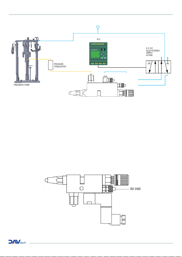
2.1 Valve Operation
The dispensing valve DA 400 is a pneumatic control component designed for precision dispense fluids low, medium or high
viscosity. Its been at rest is normally closed (even in case of power failure pneumatic), being present inside a safety spring.
The pneumatic supply, at a pressure equal to or greater than 6 bar in its lower input (see diagram connection) will result in the
withdrawal of the needle and the internal fluid flow.
The fluid flow can be modulated, as well as with the pressure to which is supplied, also by adjusting the opening of the needle
through the adjustment on the top of the valve DA 400.
2.2 Technical Specification
Model DA 400
Driving Simple or double effect
Weight 260 g
Fluid pressure Max 80 bar (double effect drive)
Driving air pressure 5 - 7 bar
Air inlet treading M5
Fluid inlet treading 1/8 gas
Fluid outlet treading
Nozzle gas treaded, nozzle with bush, luer lock needles holder, stainless steel nozzles in various shape and dimensions
Cycle speed Until a 200 cycles/min
Passage setting Micrometric or with screw
Used material Stainless steel, Widia, nickel and Teflon coated brass
Operating fluids Silicone, liquid gaskets, greases, resin, oils and various low to high viscosity fluids