DAV TECH DAS 30 Product manual

SPRAY VALVE DAS 30
DAV TECH SRL
Via Ravizza, 30 - 36075 Montecchio Maggiore (VI) - ITALY
Tel. 0039 0444 574510 - Fax 0039 0444 574324
Installation and
maintenance guide

Index
1 INTRODUCTION pag. 3
1.1 The manual
1.2 Warranty
1.3 Goods receiving
2 TECHNICAL DESCRIPTION pag. 3
2.1 Valve operation
2.2 Technical specifications
2.3 Connection diagram
3 INSTALLATION pag. 4
3.1 Mounting in the machine
3.2 Drive the valve
3.3 Fluid connection
3.4 Setting of the dispensed shot
3.5 Amount of the shot
3.6 Screw regulation
4 MAINTENANCE pag. 7
4.1 General rules
4.2 Valve Disassembly and Re-assembly
5 TROUBLESHOOTING pag. 8
5.1 Problems and solutions
6 SIZE pag. 8
7 BREAKDOWN AND DIMENSIONS pag. 9
7.1 Spare parts DAS-30
7.2 Spare parts list DAS-30
7.3 Needle
7.4 Nozzle
7.5 Air cap
7.6 Valve extender
8 SPECIAL VERSION pag. 13
Installation and maintenance guide

SPRAY VALVE DAS 30
pag.3
1 INTRODUCTION
1.1 The manual
The user guide is the document that accompanies the valve from the time of its construction and throughout the period of
use, it is therefore an integral part of the valve. It requires reading the manual before taking any action involving the valve. The
manual must be readily available for use by staff and maintenance of the valve. The user and the attendant use are required
to know the contents of this manual.
Reproduction of any part of this manual, in any form, without the express written permission of DAV Tech. The text and
illustrations in this manual are not binding, the DAV tech reserves the right, at any time and without notice, the right to make
any changes to improve the product or for reasons of character manufacturing or commercial.
1.2 Warranty
The warranty is valid for a period of 12 months from the date of commissioning and no later than 15 months from the
date delivery. The interventions carried out during the warranty period does not extend in any way the validity period of the
guarantee. The seller is not liable for defects caused by normal wear of parts which by their nature are subject to wear.
1.3 Goods receiving
The original configuration of the valve must never be changed.
Upon receipt of the goods, check that:
• The packaging is intact
• The exact correspondence of the material ordered.
2 TECHNICAL DESCRIPTION
2.1 Valve Operation
The micro-spray valve DAS 30 is designed to obtain micro-spraying of various types of fluid.
The miniaturized size is perfect for compact layouts, and its design and strenght make it ideal for who is looking for a real
cost-effective solution.
The spray valve DAS 30 can be equipped with various kind of extensions, to fit perfectly any different application.
2.2 Technical Specification
Model DAS 30
Drive Single acting
Weight 140g
Dimensions 40x25x25 mm
Max fluid pressure Max 3 bar - HP version until 12 bar
Actuating air pressure 5-6 bar
Atomizing air pressure 0,1 - 6 bar
Type inlet air Tube 6x4mm
Type inlet fluid Tube 6x4mm
Air cap For round or flat spray (various angle)
Speed Until 200 cycle/min
Adjusting Micrometric - Optionally available with opening sensor
Used materials Stainless steel
Fluids to be dispensed Oil, lubrificants, release agents, thread-lockers (PEEK Version) etc

AIR PRESSURE
REGULATOR
FLUID
PLCPLC
E.V.
3/2
E.V.
3/2
E.V.
3/2
PRESSURIZED
TANK
3 INSTALLATION
3.1 Mounting in the machine
The valve can be mounted with any orientation, using the 2 M5 holes on its
body. The distance between the valve and the point of application results in
different results. It is important that the valve is protected from dirt, shocks and
vibrations, which could impair its smooth operation. The inputs on the valve are
marked with letters: M Fluid inlet (max. 3 bar) - Z Atomizing air (0.1 - 6 bar) - S
Air command (5-6 bar).
The inputs can be moved to the back of the valve, replacing the grains (see exploded 12) assembled and going to fix
them on the inputs left free with an anaerobic sealant.
Fastening hole
2.3 Connection
diagram
Installation and maintenance guide
Automatic Spray Valve
KA-2
Copyright ALFRED SCHÜTZE Apparatebau GmbH,
2022. All rights reserved.
21
Doc-ID 0326
4 Installation
Assembly
The spray valve KA-2 can be installed in any position.
The distance between nozzle opening and application level depends on the required application
width of the material. The greater the distance between nozzle opening and application level, the
greater the application width of the material.
Securely and tightly screw the spray valve to the arm or machine!
Natural oscillation occurs in intermittent operation.
To achieve clean application, it is essential to avoid the transmission of natural oscillation both from
the machine to the spray valve and from the spray valve to the machine.
Hose installation
Control air, atomising air and material are supplied to the spray valve via three separate
connections. The connection ports are differentiated as follows (see Fig. 4.2/1):
•Atomising air (blue)
Connection Z: to 2/2-way solenoid valve
•Control air (black)
Connection S: to 3/2-way solenoid valve
•Material (transparent or white)
Connection M: to pressure tank or pump
Fig. 4.2/1
WARNING! Risk of injury!
The pneumatic energy can cause severe injury. If a component is damaged, high-pressure
materials can escape and cause injury and damage!
Rear connection
Lateral connection
SIDE
CONNECTION
BACK
CONNECTION

pag.5
3.2 Drive the valve
The DAS 30 spray valve must be actuated by two separate solenoid valves; A 3/2 way to drive and a 3/2 way to spray.
The drive pressure must be between 5 and 6 bar.
Spraying pressure between 0.1 ... 6 bar. To achieve an ideal result, the spraying air must be activated first and closed
after the drive air, to prevent dripping.
It is possible, but not advised, to control the air for opening and additional air through the same solenoid valve.
3.3 Fluid connection
The valve must be connected to a fluid supply unit (pressure tank or diaphragm pump).
3.4 Setting of the dispensed shot
The stroke stroke can be adjusted by acting on the micrometric screw located on the back of the valve body. Each
screw stroke corresponds to a 0.025 mm movement of the pin stop block. It is important not to reduce the passage
excessively by forcing the stop block to prevent needle and nozzle damage. By acting anti-clockwise on the block, the
stroke of the needle (and thus the dosed amount) increases, acting in the opposite direction the dispensed quantity
decreases.
3.5 Amount of the shot
Adjusting the amount of material (fluid) is determined by:
> Diameter of the nozzle(0.3 - 0.5 - 0.8 - 1.0 - 1.5 - 2 - 2,5 mm)
> Fluid pressure
> Pin stroke adjustment
Acting on these factors, you can adjust the amount of material you want.
Do not tighten the needle setting too firmly to avoid damaging the needle and nozzle.
Manuale DAS 90
3 INSTALLAZIONE
3.1 Montaggio della Valvola
La Valvola DAS 90 deve essere montata
utilizzando la piastra di fissaggio presente
sulla Valvola.
Deve essere garantito un buon fissaggio della
Valvola sulla macchina, stabile senza
vibrazioni e con una buona accessibilità per
la regolazione, la pulizia e la manutenzione.
3.2 Azionare la Valvola
La Valvola spray DAS 90 deve essere azionate da due elettrovalvole
separate; una da 3/2 vie per il pilotaggio (tubo nero) e una da 3/2 vie per
la nebulizzazione (tubo blu).
La pressione di azionamento deve essere compresa tra 5 e 7 bar.
La pressione di nebulizzazione tra 0,1…2.5 bar.
L’aria di nebulizzazione deve essere attivata prima e chiusa dopo l’aria di
azionamento, questo per impedire che la colla possa sporcare l’ugello e il
cappuccio.
3.3 Collegamento del materiale
La Valvola deve essere collegata ad un gruppo di alimentazione colla
(fusto sotto pressione o pompa a membrana).
Il tubo del materiale è quello trasparente di diametro 6x4.
DAV Tech Sas Via S. Pio X 6/a 36077 Altavilla Vicentina (VI) 0039 0444 574510 www.davtech.it davtech@davtech.it 6
Foro di fissaggio
Tempo aria di nebulizzazione
Tempo aria di apertura
SPRAY VALVE DAS 30
Spraying air time
Opening air time

Installation and maintenance guide
3.6 Screw regulation
The spray valve can be used with continuous or intermittent operation. In intermittent operation, the control air pressure
must be adapted to the switching frequency and material supply pressure. Under ideal operating conditions (specially
calibrated material pressure, control air pressure, needle stroke, short lines) up to 30 cycles per second are possible.
• The operating air pressure (S) must be 6 bar.
• The additional air (Z) must be adjusted so that it is turned on before the needle retracts and is turned off only after the
nozzle closes (reduces the need for maintenance).
• If the material is kept under pressure without contact with outside air, it can remain in the valve for long periods
without the valve being used.
• Use only clean, filtered material. Ideally, the control air supplied to the valve should be lightly lubricated (line air).
The additional air pressure (Z) and the material pressure (M) are closely related to each other.
The atomizing air pressure should not be significantly greater than the material pressure, otherwise back pressure could
develop which would push the material back into the nozzle.
Automatic Spray Valve
KA-2
Copyright ALFRED SCHÜTZE Apparatebau GmbH ,
2022. All rights reserved.
25
Doc-ID 0326
Operating instructions
➔The spray valve may be used in continuous or intermittent operation. In intermittent operation
the control air pressure must be matched to the switching frequency and the material feed
pressure. In ideal operating conditions (material pressure, control air pressure, needle
stroke, short lines) up to 30 cycles per second are possible.
➔The control air pressure should be 6 bar.
➔The atomising air has to be regulated so that it is switched on before the needle retracts,
and is switched off only after the nozzle closes (reduces the need for maintenance).
➔If the material is kept pressurised with no contact with the outside air, it can remain in the
valve during long periods without operation.
➔Only clean, filtered material, atomising air and control air may be used. The control air
supplied to the spray valve should ideally be lightly oiled.
➔Only for the adhesive version:
The atomising air pressure and material pressure are closely related to each other. The
atomising air pressure should not be significantly greater than the material pressure, since
otherwise back pressure can develop, pushing the material back into the nozzle.
Fig. 5.2/1
NOTE!
The flow of material can be adjusted to suit individual requirements by turning the regulating
screw (Fig. 5.2/1):
Turn screw to the right: to reduce the material flow
Turn screw to the left: to increase the material flow
NOTE!
The illustrations in these instructions may differ slightly from the actual version of the device.
Incorrect handling can damage the nozzle and nozzle needle. Only reduce the material flow (by
turning the regulating screw to the right) while the material is being dispensed. Once the nozzle
closes, do not turn the regulating screw any further to the right.
NOTE! The illustrations in these
instructions may differ slightly from the
actual version of the device. Incorrect
handling can damage the nozzle and
nozzle needle. Only reduce the material
flow (by turning the regulating screw
to the right) while the material is being
dispensed. Once the nozzle closes, do
not turn the regulating screw any further
to the right.
NOTE! The flow of material can be adjusted
to suit individual requirements by turning the
regulating screw:
Turn screw to the right:
to reduce the material flow
Turn screw to the left:
to increase the material flow

pag.7
SPRAY VALVE DAS 30
4 MAINTENANCE
4.1 General rules
The DAS 30 spray valve, thanks to the construction methods and materials used, is easy to maintain.
Minimal, simple, accurate, and constant maintenance allow for long-lasting and smooth operation in valve time, while
maintaining performance unchanged.
4.2 Valve Disassembly and Re-assembly
Before disassembling the valve:
• Clean the valve
• Disconnect it from the entire circuit
• Remove the screws (10)
• Remove the pneumatic body (9), being careful not to lose the O-rings (8)
• Remove the spring, the needle (6) and the O-ring (5)
• Unscrew the ring nut (1) from the main body (4), and together with it also the air cap (2)
• Unscrew, using a wrench, the nozzle (3)
• Clean and replace all damaged gaskets (in red) and any other parts
• Reassemble in the reverse order.
Automatic Spray Valve
KA-2
Copyright ALFRED SCHÜTZE Apparatebau GmbH ,
2022. All rights reserved.
29
Doc-ID 0326
Changing the nozzle and nozzle needle
Fig. 6.2/1
1. Depressurise all connections and stop the supply of energy and material!
2. Undo the retaining ring (1) and remove the air cap (2).
3. Unscrew the cylinder-head screws (10) and remove the end plate (9).
(Caution: the end plate is under spring tension)
4. Take care not to lose the O-rings (8) or the pressure springs (7).
5. Withdraw the nozzle needle (6) and unscrew the nozzle (3). Ensure that the O-ring (5)
stays in the main body (4); when pulling out the nozzle needle, it sometimes gets stuck on
the needle.
6. Lightly grease the new nozzle needle (6) and push it into the main body (4). Then remove
any remaining grease from the needle tip.
7. Screw the new nozzle (3) into the main body (4).
8. Only now should the end plate (9) be screwed back onto the main body (4). At this stage,
make sure that the pressure springs and O-rings are positioned correctly, as described in
point 4.
9. Screw the air cap (2) with the retaining ring (1) back onto the main body (4).
10. Perform a functional test of the device after changing the nozzle and needle!
IMPORTANT!
Always install a new nozzle (3) and nozzle needle (6) at the same time.
NOTE!
When replacing nozzles and nozzle needles that have already been in use, rinse the nozzle with
the appropriate solvent in such a way that no material residues remain. The shaft of the needle
must also be cleaned of any residual particles. Needle shafts with hardened material residues
can lead to damage of the sealing element.

PROBLEM POSSIBLE CAUSE SOLUTION
Nothing or little fluid Valve does not receive the command Check valve (solenoid valve) control. Perform
a manual test.
The pressure of the fluid is too low
or absent. Check the fluid supply pressure and, if
necessary, increase it.
The nozzle is clogged
Unscrew and clean the nozzle.
The filter is dirty (if present) Wash or replace the filter.
A tube is bent Check the status of the fluid supply pipes
Insufficient drive pressure Check drive pressure (5-7 bar)
Fluid residues present in the system Clean the system with water
Fluid out of the compass O-ring or shaped gasket on the damaged
valve body Replace O-ring or shaped gasket
Fluid flow between valve
body and fixing plate O-ring on the damaged dam reservoir Replace the O-ring of the hub
The nozzle dries even if
the valve is not piloted Presence of dirt in the nozzle Clean or replace the nozzle.
The valve opens late Insufficient drive pressure Check drive pressure 5-7 bar
O-ring on the damaged spike Replace the O-ring on the pin
Splashed irregularly Insufficient spraying pressure Check spraying pressure
(0,1…2,5 bar)
Dirt in the air cap Clean the air cap
5 TROUBLESHOOTING
5.1 Problems and solutions
The search for defects in the operation should be performed only by personnel qualified respecting the safety rules
in force.
6 DIMENSIONS
Installation and maintenance guide
Automatic Spray Valve
KA-2
Copyright ALFRED SCHÜTZE Apparatebau GmbH ,
2022. All rights reserved.
17
Doc-ID 0326
Dimensions
Fig. 3.3/1
Automatic Spray Valve
KA-2
Copyright ALFRED SCHÜTZE Apparatebau GmbH ,
2022. All rights reserved.
17
Doc-ID 0326
Dimensions
Fig. 3.3/1

7.2 Lista componenti DAS-30
STANDARD VERSION HIGH PRESSURE (HP) VERSION (25 bar)
Pos Code Q.ty Description
1See next table 1 Air cap
2See next table 1 Nozzle
3410028 1 Collar
4510025 1 Main body
5640006 1 O-ring
6220089 3 M5 tting
7640026 1 Seal
8See next table 1 Needle
9640366 1 O-ring
10 820017 1 Pressure spring
11 610090 1 Regulation block
12 640000 3 O-ring
13 510028 1 Pneumatic body
14 610021 3 Grub screws
15 610008 3 Screws
16 650004 1 Conical element
17 820077 1 Spring
18 610017 1 Grub screw
19 220089 3 Fitting
GASKETKIT-DAS30
GASKET KIT COMPLETE
Pos Code Q.ty Description
1See next table 1 Air cap
2See next table 1 Nozzle
3410028 1 Collar
4510938 1 Main Body HP
5640006 1 O-ring
6220089 3 M5 Fitting
7640026 1 Seal
8See next table 1 Needle
9640366 1 O-ring
10 820014 1 Pressure spring HP
11 610090 1 Regulation block
12 640000 3 O-ring
13 510028 1 Pneumatic body
14 610021 3 Grub screws
15 610008 3 Screws
16 650004 1 Conical element
17 820077 1 Spring
18 610017 1 Grub screw
19 220089 3 Fitting
20 320564 1 Needle guide HP
21 640045 1 Quad ring HP
GASKETKIT-DAS30HP
GASKET KIT COMPLETE
air cap nozzle needle
3
1
5
4
19
8
2
7911
12
13 15
14
16 17
18
10
ONLY HP VERSION
20
21
pag.9
7.1 Spare parts DAS 30
7 SPARE PARTS
SPRAY VALVE DAS 30
ONLY HP VERSION
Installation and maintenance guide
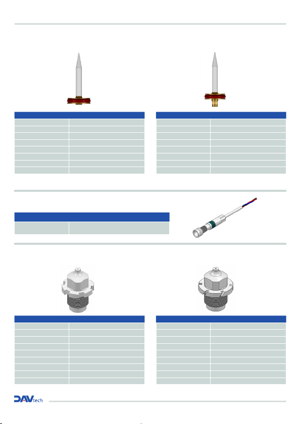
7.3 Needle
7.4 Ugello
STANDARD NEEDLE NEEDLE FOR SENSOR
Code Description
110155 NEEDLE 0,2-0,3 MM
110156 NEEDLE 0,5 MM
110157 NEEDLE 0,8 MM
110158 NEEDLE 1,0 MM
110159 NEEDLE 1,2 MM
110160 NEEDLE 1,5 MM
110161 NEEDLE 2,0 MM
110162 NEEDLE 2,5 MM
Code Description
110696 NEEDLE 0,2-0,3 MM
111062 NEEDLE 0,5 MM
111930 NEEDLE 0,8 MM
111931 NEEDLE 1,0 MM
111932 NEEDLE 1,2 MM
111933 NEEDLE 1,5 MM
111934 NEEDLE 2,0 MM
111935 NEEDLE 2,5 MM
Automatic Spray Valve
KA-2
Copyright ALFRED SCHÜTZE Apparatebau GmbH ,
2022. All rights reserved.
43
Doc-ID 0326
Nozzle needles
8.4.1 Standard version
Nozzle needle, stainless steel, dia. 3 x 27 mm (7)
Item no.
Description
110155
Nozzle needle, 0.2 / 0.3 mm, complete, Viton®
110156
Nozzle needle, 0.5 mm, complete, Viton®
110157
Nozzle needle, 0.8 mm, complete, Viton®
110158
Nozzle needle, 1.0 mm, complete, Viton®
110159
Nozzle needle, 1.2 mm, complete, Viton®
110160
Nozzle needle, 1.5 mm, complete, Viton®
110161
Nozzle needle, 2.0 mm, complete, Viton®
110162
Nozzle needle, 2.5 mm, complete, Viton®
8.4.2 Standard V4A version
Nozzle needle, V4A, dia. 3 x 27 mm (7)
Item no.
Description
114777
Nozzle needle, 0.2 / 0.3 mm, V4A, complete, Viton®
111758
Nozzle needle, 0.5 mm, V4A, complete, Viton®
111926
Nozzle needle, 0.8 mm, V4A, complete, Viton®
8.4.3 Adhesive version
Nozzle needle, adhesive, stainless steel, dia. 3 x 27 mm (7)
Item no.
Description
110169
Nozzle needle, adhesive, 0.2/0.3 mm, complete, Viton®
110170
Nozzle needle, adhesive, 0.5 mm, complete, Viton®
110171
Nozzle needle, adhesive, 0.8/1.0 mm, complete, Viton®
110172
Nozzle needle, adhesive, 1.2 mm, complete, Viton®
110173
Nozzle needle, adhesive, 1.5 mm, complete, Viton®
110174
Nozzle needle, adhesive, 2.0 mm, complete, Viton®
Automatic Spray Valve
KA-2
Copyright ALFRED SCHÜTZE Apparatebau GmbH ,
2022. All rights reserved.
45
Doc-ID 0326
8.5.2 Connecting the sensor
For information on the electrical connection of the needle sensor, please refer to the enclosed
documentation for the sensor in the appendix (Chapter 12 "Appendix").
8.5.3 Nozzle needle for sensor
When using a raster needle sensor, one of the following nozzle needles is needed.
8.5.3.1 Standard version
Nozzle needle, stainless steel, dia. 3 x 31 mm (7)
Item no.
Description
110969
Nozzle needle, 0.2/0.3 mm, complete, NA, Viton®
111062
Nozzle needle, 0.5 mm, complete, NA, Viton®
111930
Nozzle needle, 0.8 mm, complete, NA, Viton®
111931
Nozzle needle, 1.0 mm, complete, NA, Viton®
111932
Nozzle needle, 1.2 mm, complete, NA, Viton®
111933
Nozzle needle, 1.5 mm, complete, NA, Viton®
111934
Nozzle needle, 2.0 mm, complete, NA, Viton®
111935
Nozzle needle, 2.5 mm, complete, NA, Viton®
8.5.3.2 Adhesive version
Nozzle needle, adhesive, stainless steel, dia. 3 x 31 mm (7)
Item no.
Description
112406
Nozzle needle, adhesive, 0.2/0.3 mm, complete, NA, Viton®
112405
Nozzle needle, adhesive, 0.5 mm, complete, NA, Viton®
112163
Nozzle needle, adhesive, 0.8/1.0 mm, complete, NA, Viton®
112513
Nozzle needle, adhesive, 1.2 mm, complete, NA, Viton®
112514
Nozzle needle, adhesive, 1.5 mm, complete, NA, Viton®
112515
Nozzle needle, adhesive, 2.0 mm, complete, NA, Viton®
WARNING! Electrical hazard!
Work on the electrical equipment must only be carried out by qualified personnel in accordance
with the safety regulations.
Before beginning work, the electrical supply must be switched off, and secured against being
switched back on.
Special custom versions available on request.
Code Description
210110 NOZZLE 0,2 MM
210111 NOZZLE 0,3 MM
210112 NOZZLE 0,5 MM
210113 NOZZLE 0,8 MM
210114 NOZZLE 1,0 MM
210115 NOZZLE 1,2 MM
210116 NOZZLE 1,5 MM
210117 NOZZLE 2,0 MM
210118 NOZZLE 2,5 MM
Automatic Spray Valve
KA-2
Copyright ALFRED SCHÜTZE Apparatebau GmbH,
2022. All rights reserved.
38
Doc-ID 0326
8.2.4 Special round spray pattern version
Air cap, round spray pattern, special swirl valve
Item no.
Description
310197
Air cap, round spray pattern, special swirl valve, 0.2–
1.0 mm
Nozzles (3.0)
8.3.1 Standard version
Nozzle, stainless steel, dia. 12 x 18 mm, AF size 6
Item no.
Description
210110
Nozzle, 0.2 mm, stainless steel, 12 x 18 mm, AF size 7
210111
Nozzle, 0.3 mm, stainless steel, 12 x 18 mm, AF size 7
210112
Nozzle, 0.5 mm, stainless steel, 12 x 18 mm, AF size 7
210113
Nozzle, 0.8 mm, stainless steel, 12 x 18 mm, AF size 7
210114
Nozzle, 1.0 mm, stainless steel, 12 x 18 mm, AF size 7
210115
Nozzle, 1.2 mm, stainless steel, 12 x 18 mm, AF size 7
210116
Nozzle, 1.5 mm, stainless steel, 12 x 18 mm, AF size 7
210117
Nozzle, 2.0 mm, stainless steel, 12 x 18 mm, AF size 7
210118
Nozzle, 2.5 mm, stainless steel, 12 x 18 mm, AF size 7
The appropriate nozzle needles and air caps can be found in Chapter 8.4.1 and Chapter 8.2.1.
Automatic Spray Valve
KA-2
Copyright ALFRED SCHÜTZE Apparatebau GmbH ,
2022. All rights reserved.
39
Doc-ID 0326
8.3.2 Standard/swirl version
Nozzle, swirl, stainless steel, 12 x 18 mm, AF size 6
Item no.
Description
210776
Nozzle, swirl, 0.2 mm, stainless steel, 12 x 18 mm, AF
size 7
210777
Nozzle, swirl, 0.3 mm, stainless steel, 12 x 18 mm, AF
size 7
210778
Nozzle, swirl, 0.5 mm, stainless steel, 12 x 18 mm, AF
size 7
211024
Nozzle, swirl, 0.6 mm, stainless steel, 12 x 18 mm, AF
size 7
211025
Nozzle, swirl, 0.7 mm, stainless steel, 12 x 18 mm, AF
size 7
210779
Nozzle, swirl, 0.8 mm, stainless steel, 12 x 18 mm, AF
size 7
210780
Nozzle, swirl, 1.0 mm, stainless steel, 12 x 18 mm, AF
size 7
210781
Nozzle, swirl, 1.2 mm, stainless steel, 12 x 18 mm, AF
size 7
210782
Nozzle, swirl, 1.5 mm, stainless steel, 12 x 18 mm, AF
size 7
210783
Nozzle, swirl, 1.8 mm, stainless steel, 12 x 18 mm, AF
size 7
210784
Nozzle, swirl, 2.0 mm, stainless steel, 12 x 18 mm, AF
size 7
The appropriate nozzle needles and air caps can be found in Chapter 8.4.1 and Chapter 8.2.1.
STANDARD NOZZLE SPIN NOZZLE
Code Description
210776 NOZZLE 0,2 MM
210777 NOZZLE 0,3 MM
210778 NOZZLE 0,5 MM
210779 NOZZLE 0,8 MM
210780 NOZZLE 1,0 MM
210781 NOZZLE 1,2 MM
210782 NOZZLE 1,5 MM
210783 NOZZLE 2,0 MM
210784 NOZZLE 2,5 MM
COMPLETE SENSOR DAS-30
Code Description
320314 NEEDLE OPEN/CLOSE DETECTING SENSOR
Automatic Spray Valve
KA-2
Copyright ALFRED SCHÜTZE Apparatebau GmbH,
2022. All rights reserved.
44
Doc-ID 0326
Raster needle sensing
In the KA-2, a raster needle sensor can optionally be installed, the inductive sensor can be used to
monitor whether the needle is open.
Important: If damaged, use a different nozzle needle!
Sensor spindle, KA-2, complete
Item no.
Description
320314
Sensor spindle, KA-2, complete
In conjunction with the appropriate nozzle needle (see Chapter: 8.5.3).
8.5.1 Adjusting the sensor
Fig. 4.5/1
1. Glue the M4 x 0.5 screw sensor (2) into the sensor receptacle (1) over an installation
length of 14.5 mm using a high-strength threadlocker. (See drawing)
2. Screw the regulating spindle (5) in until the needle is closed and no more material
emerges from the nozzle.
3. Connect the sensor to a control device in order to adjust it.
4. Then push the spring (3) and the spindle guide (4) onto the sensor and insert them
together into the regulating spindle until a signal appears.
5. Unscrew the regulating spindle until the signal disappears (up to at most 6 clicks). If the
signal from the sensor has still not disappeared, finely adjust the sensor using the
spindle guide until the signal disappears.
6. Perform the fine adjustment by pushing the spindle guide back against the spring, so
that the sensor can be turned in the regulating spindle until the signal disappears.
7. Allow the spindle guide to latch back into the groove of the regulating spindle.

pag.11
SPRAY VALVE DAS 30
7.5 Air cap
7.6 Valve extender (Standard)
FLAT AIR CAP
60° (STANDARD)
RADIAL DISPENSING VALVE EXTENDER 360° - L:100 mm
FLAT AIR CAP
ROUND AIR CAP
ROUND AIR CAP
15°
FRONTAL DISPENSING VALVE EXTENDER - L:100 mm
Code Description
310032 FOR NOZZLE 0,2-1,0 MM
310033 FOR NOZZLE 1,2-1,5 MM
310079 FOR NOZZLE 1,8-2,0 MM
310090 FOR NOZZLE 2,5 MM
Codice Description
310034 FOR NOZZLE 0,2-1,0 MM
310035 FOR NOZZLE 1,2-1,5 MM
310080 FOR NOZZLE 1,8-2,0 MM
310091 FOR NOZZLE 2,5 MM
90°
Code Description
310036 FOR NOZZLEO 0,2-1,0 MM
310037 FOR NOZZLE 1,2-1,5 MM
310166 FOR NOZZLE 1,8-2,0 MM
310167 FOR NOZZLE 2,5 MM
Ø 4 mm Ø 4 mm
45°
Code Description
310038 FOR NOZZLE 0,2-1,0 MM
310039 FOR NOZZLE 1,2-1,5 MM
Automatic Spray Valve
KA-2
Copyright ALFRED SCHÜTZE Apparatebau GmbH ,
2022. All rights reserved.
33
Doc-ID 0326
8 Spare parts and accessories
General and safety instructions for use
When ordering nozzle sets as spare parts (nozzle needle, air cap and nozzle), please state required
size. Nozzle sets should always be replaced together!
Available nozzles, air caps and needle sizes (dia.):
0.2 mm / 0.3 mm / 0.5 mm / 0.8 mm / 1.0 mm / 1.2 mm / 1.5 mm / 2.0 mm / 2.5 mm
Special nozzles, needles and air caps can be developed for your particular application upon
request!
Only use swirl nozzles in combination with the matching round spray cap!
Air caps
8.2.1 Standard version
Air cap, flat spray pattern, dia. 20 x 14.5 mm, 45°
Item no.
Description
310038
Air cap, flat spray pattern, 0.2–1.0 mm, 20 x 14.5 mm
310039
Air cap, flat spray pattern, 1.2–1.5 mm, 20 x 14.5 mm
Air cap, flat spray pattern, dia. 20 x 14.5 mm, 60°, standard version
Item no.
Description
310032
Air cap, flat spray pattern, 0.2–1.0 mm, 20 x 14.5 mm
310033
Air cap, flat spray pattern, 1.2–1.5 mm, 20 x 14.5 mm
310079
Air cap, flat spray pattern, 1.8–2.0 mm, 20 x 14.5 mm
310090
Air cap, flat spray pattern, 2.5 mm, 20 x 14.5 mm
Air cap, flat spray pattern, dia. 20 x 14.5 mm, 90°
Item no.
Description
310036
Air cap, flat spray pattern, 0.2–1.0 mm, 20 x 14.5 mm
310037
Air cap, flat spray pattern, 1.2–1.5 mm, 20 x 14.5 mm
310166
Air cap, flat spray pattern, 1.8–2.0 mm, 20 x 14.5 mm
310167
Air cap, flat spray pattern, 2.5 mm, 20 x 14.5 mm
Automatic Spray Valve
KA-2
Copyright ALFRED SCHÜTZE Apparatebau GmbH,
2022. All rights reserved.
34
Doc-ID 0326
Air cap, flat spray pattern, dia. 20 x 14.5 mm, 45°, VA
Item no.
Description
310512
Air cap, flat spray pattern, 0.2–1.0 mm, 20 x 14.5 mm,
VA
311015
Air cap, flat spray pattern, 1.2–1.5 mm, 20 x 14.5 mm,
VA
Air cap, flat spray pattern, dia. 20 x 14.5 mm, 60°, VA, standard version
Item no.
Description
310209
Air cap, flat spray pattern, 0.2–1.0 mm, 20 x 14.5 mm, VA
310420
Air cap, flat spray pattern, 1.2–1.5 mm, 20 x 14.5 mm, VA
310513
Air cap, flat spray pattern, 1.8–2.0 mm, 20 x 14.5 mm, VA
310944
Air cap, flat spray pattern, 2.5 mm, 20 x 14.5 mm, VA
Air cap, flat spray pattern, dia. 20 x 14.5 mm, 90°, VA
Item no.
Description
310584
Air cap, flat spray pattern, 0.2–1.0 mm, 20 x 14.5 mm, VA
Air cap, flat spray pattern, 1.2–1.5 mm, 20 x 14.5 mm, VA
310584
Air cap, flat spray pattern, 1.8–2.0 mm, 20 x 14.5 mm, VA
Air cap, flat spray pattern, 2.5 mm, 20 x 14.5 mm, VA
Air cap, round spray pattern, dia. 20 x 11 mm, 15°
Item no.
Description
310034
Air cap, round spray pattern, 0.2–1.0 mm, 20 x 11 mm
310035
Air cap, round spray pattern, 1.2–1.5 mm, 20 x 11 mm
310080
Air cap, round spray pattern, 1.8–2.0 mm, 20 x 11 mm
310091
Air cap, round spray pattern, 2.5 mm, 20 x 11 mm
Air cap, round spray pattern, dia. 20 x 11 mm, 15°, VA
Item no.
Description
310370
Air cap, round spray pattern, 0.2–1.0 mm, 20 x 11 mm, VA
310366
Air cap, round spray pattern, 1.2–1.5 mm, 20 x 11 mm, VA
310385
Air cap, round spray pattern, 1.8–2.0 mm, 20 x 11 mm, VA
310464
Air cap, round spray pattern, 2.5 mm, 20 x 11 mm, VA
Special custom versions available on request.
Pos Code Description
1 640203 O-RING
2 230747 RADIAL DISPENSING VALVE EXTENDER
3 410028 NUT
Pos Code Description
1 640203 O-RING
2 231515
FRONTAL DISPENSING VALVE EXTENDER
3 410028 NUT
3
1
2
3
1
2

Installation and maintenance guide
Ø 8 mm
Pos Description vers. Code
1
INNER TUBE STD (100 mm)
INNER TUBE HP (100 mm)
INNER TUBE STD (200 mm)
INNER TUBE HP (200 mm)
1.1
1.2
1.3
1.4
850129
851134
850096
854821
2OUTER TUBE (100 mm)
OUTER TUBE (200 mm)
2.1
2.2
850130
850097
3 BELL 220197
4 O-RING 640039
5 O-RING 640366
6
NOZZLE 0,4 mm
NOZZLE 0,6 mm
NOZZLE 0,8 mm
5.1
5.2
5.3
211206
211343
211327
7
NEEDLE STD (100 mm)
NEEDLE VERS. SENSOR
NEEDLE STD (200 mm)
6.1
6.2
6.3
110432
112929
112601
8 COLLAR 410028
Pos Description vers. Code
1
INNER TUBE STD (100 mm)
INNER TUBE HP (100 mm)
INNER TUBE STD (200 mm)
INNER TUBE HP (200 mm)
1.1
1.2
1.3
1.4
850129
851134
850096
854821
2OUTER TUBE COMPLETE (100 mm)
OUTER TUBE COMPLETE (200 mm)
2.1
2.2
850215
850669
3 O-RING 640366
4 NOZZLE 0,5 mm 210348
5
NEEDLE STD (100 mm)
NEEDLE VERS. SENSOR
NEEDLE STD (200 mm)
6.1
6.2
6.3
110432
112929
112601
6 COLLAR 410028
Ø 8 mm
RADIAL DISPENSING VALVE EXTENDER 360° - L:100/200 mm FRONTAL DISPENSING VALVE EXTENDER - L:100/200 mm
1
2
3
4
5
6
1
2
3
4
5
6
7
8

pag.13
SPRAY VALVE DAS 30
8 SPECIAL VERSION :
The DAS 30 valve exists in many special variants:
- PEEK version, for aggressive or reactive products
- Extension extension for radial spraying (draw design) Extensions are available in lengths of 100, 200, 300,
400 and 500 mm and allow to dispense holes and cylinders with low and medium viscosities such as oils
and greases.
- Version with sensor for objectization after valve opening.
- Special versions with extensions and nozzles for spraying in difficult access areas. For example, with tilted
nozzles 45 °, with double spraying nozzles etc.
- Versions with special seals for extremely high temperature working areas (up to 150°).

We reserve the right to modify at any time, without notice, the specifications, dimensions and weights in this manual.
The illustrations are not binding.
DAV TECH SRL Via Ravizza, 30 - 36075 Montecchio Maggiore (VI) - ITALY - Tel. 0039 0444 574510 - Fax 0039 0444 574324
Table of contents
Other DAV TECH Control Unit manuals

DAV TECH
DAV TECH DA 400 Product manual

DAV TECH
DAV TECH DAS 50N Product manual

DAV TECH
DAV TECH DA 400 EV Product manual

DAV TECH
DAV TECH DA 400 EVO Product manual

DAV TECH
DAV TECH DA 250 Product manual

DAV TECH
DAV TECH DA 600 Product manual

DAV TECH
DAV TECH DAV 300 MAN Product manual

DAV TECH
DAV TECH DAS 90 Product manual

DAV TECH
DAV TECH DAV 150 Product manual
Popular Control Unit manuals by other brands

MacDon
MacDon FM100 installation instructions

Emerson
Emerson Varec 5010 Series Installation, operation and maintanance instructions

Bogen
Bogen RIO1S manual

Heinner
Heinner HAC-HS09WH++ installation guide

SOMAS
SOMAS SKV Service and operating instruction

Neptune
Neptune AquaController Apex EnergyBar 4 Setup guide


