DAV TECH DAV 300 MAN Product manual

DISPENSING VALVE WITH HAND-GRIP
DAV 300 MAN - DAV 400 MAN
Installation and
maintenance guide
DAV TECH SRL
Via Ravizza, 30 - 36075 Montecchio Maggiore (VI) - ITALY
Tel. 0039 0444 574510 - Fax 0039 0444 574324

Index
1 INTRODUCTION pag. 3
1.1 The manual
1.2 Warranty
1.3 Goods receiving
2 TECHNICAL DESCRIPTION pag. 3
2.1 Valve operation
2.2 Technical specifications
2.3 Connection diagram
3 INSTALLATION pag. 4
3.1 Drive the valve
3.2 Fluid connection
3.3 Setting of the dispensed shot
3.4 Amount of the shot
4 MAINTENANCE pag. 5
4.1 General rules
4.2 Valve Disassembly
4.3 Valve Re-assembly
5 TROUBLESHOOTING pag. 6
5.1 Problems and solutions
6 ESPLOSO E DIMENSIONI pag. 7
6.1 Breakdown
6.2 Components
Installation and maintenance guide

DISPENSING VALVE WITH HAND-GRIP DAV 300 MAN - DAV 400 MAN
pag.3
1 INTRODUCTION
1.1 The manual
The user guide is the document that accompanies the valve from the time of its construction and throughout the period of
use, it is therefore an integral part of the valve. It requires reading the manual before taking any action involving the valve. The
manual must be readily available for use by staff and maintenance of the valve. The user and the attendant use are required
to know the contents of this manual.
Reproduction of any part of this manual, in any form, without the express written permission of DAV Tech. The text and
illustrations in this manual are not binding, the DAV tech reserves the right, at any time and without notice, the right to make
any changes to improve the product or for reasons of character manufacturing or commercial.
1.2 Warranty
The warranty is valid for a period of 12 months from the date of commissioning and no later than 15 months from the
date delivery. The interventions carried out during the warranty period does not extend in any way the validity period of the
guarantee. The seller is not liable for defects caused by normal wear of parts which by their nature are subject to wear.
1.3 Goods receiving
The original configuration of the valve must never be changed.
Upon receipt of the goods, check that:
• The packaging is intact
• The exact correspondence of the material ordered.
2 TECHNICAL DESCRIPTION
2.1 Valve operation
The dispensing valves with hand grip DAV 300 MAN - DAV 400 MAN are pneumatically drived components, designed for
accurate dispensing of lubricants at low, medium or high viscosity.
The exchange of the compressed air, at a pressure equal to or greater than 6 bar, will result in the emptying of the volumetric
chamber and the relative dispensing of a quantity of fluid constant and adjustable.
2.2 Technical specification
Model DAV 300 MAN - DAV 400 MAN
Operation mode Double Acting
Weight 1.270 g (DAV 300 MAN-O) 1.540 g (DAV 300 MAN-V)
Fluid pressure inlet Min 20 bar - Max 200 bar
Quantity dispensable DAV 300 MAN: 0,1 cm³ - 2,0 cm³ - DAV 400 MAN: 1,0 cm³ - 6,0 cm³
Actuating air pressure 5 - 7 bar
Inlet air M5 for ø 6 mm hose
Inlet fluid thread 1/4 BSP
Outlet fluid M5 threaded with luer lock holder or fitting 1/8 BSP female
Speed Up to 60 cycles / min
Adjusting the amount dosed Micrometric with block screw
Used materials Stainless steel, anodized aluminum
Fluids to be dispensed Greases and lubricants up to NLGI 3-1000000 mPa s

We reserve the right to modify at any time, without notice, the specifications, dimensions and weights in this datasheet. The illustrations are not binding.
FEEDING PUMPS FOR GREASE
DAV Tech pumps are ideal to feed grease and lubricants,contained in cans or drums, to the valve DAV 400 MAN.
Pumps are available for cans from 0.5 up to 5 kg and for 5 to 200 kg drums.
NOZZLES FOR VALVE DAV 400 MAN
The valve DAV 400 MAN is equipped with luer lock nozzle holder or alternatively with a threaded nozzle 1/8 BSP
female. We can also design and build special nozzles (multi-point, radial, etc.) to meet the customer needs.
DRIVE THE VALVE DAV 400 MAN
The valve DAV 400 MAN have to be kept constantly fed with air at a pressure between 5 and 7 bar.
The pneumatic switch valve is integrated in the hand-grip. The quantity dispensed is independent of time for which
the operator presses the trigger (in addition to the minimum time required for dosage).
Connection diagram
DISPENSE
SWITCH
(OPTIONAL)
LUBRICANT
(PRESSURE 20-200 bar)
PNEUMATIC
PUMP FLUID INLET POSSIBLE
BOTH UNDER OR BEHIND
THE HAND-GRIP
2.3 Connection diagram
3 INSTALLATION
3.1 Drive the valve
The DAV 300 MAN and DAV 400 MAN valves operate pneumatically with a double effect, by pressing the trigger on
the handle.
3.2 Connection of the fluid
The valve must be connected to a power supply unit, which guarantees a pressure between 20 and 200 bar.
A flexible hose, resistant to high pressures, must be connected to the fitting placed in the smallest part of the valve.
In the case of the model DAV 300 (400) MAN there is only one product input, in the case of the model DAV 300 (400)
MAN O there are 2 inputs for both the control air and the grease. In one case they are placed at the base of the grip while
in the other case (to be used alternatively), on the back of the handle.
Installation and maintenance guide
Possible material
and air input
Possible material
and air input

pag.5
3.3 Adjusting the amount of material
The amount of product is dispensable functional to fill volume of the room, set by turning the adjustment, mounted
on valve head displacement.
A grain then allows you to lock the adjustment and prevent tampering.
3.4 Quantity dispensable
Being valves volumetric quantity is dispensable only functional to the volume of the chamber set.
In any case it is necessary consider the minimum time required for charging and discharging of the valve, the times
that vary with the pressure of the incoming fluid, its viscosity, and depending on the type of applicator connected
to the nozzle valve.
DISPENSING VALVE WITH HAND-GRIP DAV 300 MAN - DAV 400 MAN
4 MAINTENANCE
4.1 General rules
Le valvole DAV 300 MAN e DAV 400 MAN, thanks to construction methods and materials used are easy to
maintain. Minimal maintenance , simple, accurate and allow a steady long-term operation and regular time of the
valve, maintaining unchanged performance.
4.2 Valve disassembly
Before disassembling the valve:
1) Clean the outside
2) Release the pressure from the system
3) Disconnect the power supply of lubricant to the valve
4) Key 4mm remove the 4 tie rods present in the head and foot valve
5) Remove various aluminum bodies
6) Remove the needle and the volumetric chamber
7) If necessary, unscrew the air piston needle from the spool.
4.3 Valve reassembly
After it has been cleaned thoroughly and have replaced all the damaged parts (especially the seals,scrapers etc.),
reassemble in reverse order of disassembly little lubrication parts and seals with grease fittings.
Be careful not to overdo the tightening of the 4 tie rods, to avoid damage.
5 TROUBLESHOOTING
5.1 Problems and solutions
The search for defects in the operation should be performed only by personnel qualified respecting the safety rules in force.
PROBLEM POSSIBLE CAUSE SOLUTION
The lubricant does not
come out The valve does not receive the command Check the control (solenoid) of valve. Perform
a manual test.
The pressure of the grease is too low or
absent.
Check the pressure of the power supply fluid
and possibly increase in range 20/200 bar
The nozzle is clogged Remove and clean the nozzle.
The filter is dirty (if any) Clean or replace the filter.
A tube is bent Check the fluid supply pipe
Actuating pressure tire Ensure sufficient pressure to drive (5-7 bar)
The lubricant has a viscosity too high
The valves can DAV 100 and DAV 200
dispense lubricant viscosity max. 1,000,000 m
Pa s and NLGI 3
Lubricant leakage retired Molded seals or gaskets Replace the damaged needle or needle shaped

Installation and maintenance guide
6 BREAKDOWN AND DIMENSIONS
42
43
39
42
47
41
40
10
44
26
31
31
33
34
32
30
34
25
24 38
35 36 37
21
22
23
27
32
28
29
49
11
48
9
15
20
17
19
18
50
14
2
10
1
16
7
4
13
5
49
10
8
6
7
46
45
3
5
6.2 Breakdown DAV- 300/400MANO - HORIZONTAL HANDLE GRIP

pag.7
DISPENSING VALVE WITH HAND-GRIP DAV 300 MAN - DAV 400 MAN
Ref. Description Code
10- RING 10005121
2UPPER LIP SEAL 18365000
3LOWER LIP SEAL 18331100
4MAGNET RING 10001528
50- RING 20001590
60- RING 18223200
7VARISEAL 28223201
8WASHER 10001595
9FLAT HEAD SCREW 18424105
10 0- RING 38232100
11 0- RING 18222500
12 0- RING 18227700
13 VOLUMETRIC CHAMBER DAV-300 10001583
13 bis VOLUMETRIC CHAMBER DAV-400 10001583
14 NEEDLE 10001586
15 PNEUMATIC PISTON 10001591
16 BUSH 10005113
17 FLAT HEAD SCREW 28423900
18 NUT 18400700
19 GOLFARE 18447200
20 FASTENING 10002007
21 0- RING 48223705
22 0- RING 28220900
23 HANDLE SPRING 18135000
24 AIR FITTING 18589300
25 INLET NIPPLEX 12258400
26 0- RING 38221400
27 HANDLE SPRING PIN 18460002
28 HANDLE SCREW COMPLETE 18515504
29 FITTING CAP 28639300
30 SINTERIZED DISC 14222200
31 BALL 38206600
32 FLAT HEAD SCREW 40004734
33 FITTING CAP 18430001
34 SHAPED GASKET 28259300
35 LEVER 14202100
36 HANDLE VALVE PISTON 14222001
37 HANDLE VALVE BODY 14241500
38 HANDLE BODY 10006426
39 SCREW 40005147
40 PIN 10001589
41 GRUB SCREW 18512700
42 NUT 18411000
43 MICROMETRIC REGULATION 10001588
44 STOPPER 10001587
45 FRONTAL PLATE DAV-300/400 10005068
46 FRONTAL BODY 10004922
47 REGULATION BODY 10004918
48 PNEUMATIC BODY 10004919
49 MID BODY DAV-300 10004920
49 bis MID BODY DAV-400 10004920
50 NUT 60002213
HORIZONTAL HANDLE GRIP COMPLETE 0006033
GASKET KIT COMPLETE (HANDLE GRIP GASKET NOT INCLUDED) GASKETKIT-DAV300400
6.3 Components DAV- 300/400MANO

Installation and maintenance guide
6.4 Breakdown DAV- 300/400MANV - VERTICAL HANDLE GRIP
1
1
4
1
1
1
1
1
1
6
1
1
1
1
1
2
1
1
1
1
1
1
1
1
1
1
1
1
1
1
1
4
2
1
1
5
25
6
26
18
53
4
29
51
27
35
56
1
47
44
54
55
19
31
3
57
2
36
37
14
15
12
13
9
8
7
46
51
45
43
41
51
22
52
34
16
32
38
33
42
40
24
23
50
47
39
20
30
21
28
48
10
11
17
49

pag.9
DISPENSING VALVE WITH HAND-GRIP DAV 300 MAN - DAV 400 MAN
Ref. Description Code
1BUSH 10005113
2HANLDE VALVE PISTON 14222001
3HANLDE VALVE BODY 14241500
4FLAT HEAD SCREW 48423900
5FASTENING 10002008
6FIXING PLATE 20002007
7BLACK HOSE 150MM 18589400
8BLACK HOSE 115MM 18589400
9AIR FITTING 28589100
10 AIR FITTING 18589102
11 GRUB SCREW 28461700
12 FLAT HEAD SCREW 18424304
13 SINTERIZED DISC 14222200
14 LEVER 14247300
15 HANDLE FRONTAL BODY 14247200
16 HANDLE BODY 14247100
17 HANDLE HEAD 10002026
18 SCREW 40005147
19 INLET NIPPLEX 10004850
20 SHAPED GASKET 18259500
21 NUT 60002213
22 AIR FITTING 28634201
23 PIN 10001589
24 GRUB SCREW 18512700
25 NUT 18411000
26 MICROMETRIC REGULATION 10001588
27 STOPPER 10001587
28 FRONTAL BODY 10004922
29 REGULATION BODY 10004918
30 PNEUMATIC BODY 10004919
31 SCREW 40001593
32 CONNECTION BODY 10004923
33 MID BODY DAV-300 10004921
33 bis MID BODY DAV-400 10004920
34 FIXING KEY 13234403
35 FLAT HEAD SCREW 18424105
36 O - RING 28220900
37 HANDLE SPRING 18135000
38 GRUB SCREW 18460002
39 O - RING 18221400
40 O - RING 10001590
41 O - RING 10005121
42 UPPER LIP SEAL 18365000
43 LOWER LIP SEAL 18331100
44 MAGNET RING 10001528
45 O - RING DAV-300 18227302
45 bis O - RING DAV-400 10001590
46 O - RING 18223200
47 VARISEAL 28223201
48 O - RING 18233000
49 O - RING 18229301
50 WASHER 10005384
51 O - RING 38232100
52 O - RING 18222500
53 O - RING 18227700
54 VOLUMETRIC CHAMBER DAV-300 10001584
54 BIS VOLUMETRIC CHAMBER DAV-400 10001583
55 NEEDLE 10001586
56 PNEUMATIC PISTON 10001591
57 O - RING 48223705
VERTICAL HANDLE GRIP COMPLETE 0004576
GASKET KIT COMPLETE (ESCLUSE GUARNIZIONI IMPUGNATURA) GASKETKIT-DAV300400
6.5 Components DAV- 300/400MANV

We reserve the right to modify at any time, without notice, the specifications, dimensions and weights in this manual.
The illustrations are not binding.
DAV TECH SRL Via Ravizza, 30 - 36075 Montecchio Maggiore (VI) - ITALY - Tel. 0039 0444 574510 - Fax 0039 0444 574324
Declaration of Incorporation
according to the EU Machinery Directive 2006/42/EG, Annex II, 1.B for partly completed machinery
Manufacturer:
DAV Tech Srl
Via Ravizza, 30 - 36075 Montecchio Maggiore
VICENZA - ITALY
Person residing within the Community authorised to compile the relevant technical documentation:
Andrea Grazioli
DAV Tech Srl
Via Ravizza, 30 - 36075 Montecchio Maggiore
VICENZA - ITALY
Description and identification of the partly completed machinery:
Type: Volumetric valves
Model: DAV 100, DAV 200, DAV 300, DAV 400, DAV 100 MAN, DAV 200 MAN, DAV 300 MAN, DAV 400 MAN.
It is also declared that the relevant technical documentation has been compiled in accordance with part B of
Annex VII.
It is expressly declared that the partly completed machinery the machinery fulfils all relevant provisions of the
following EU Directives:
• 2006/42/CE
• 2006/42/EG
• 95/16/EG
The manufacturer or his authorised representative undertakes to transmit, in response to a reasoned request by the
national authorities, relevant information on the partly completed machinery. This transmission takes place:
This does not affect the intellectual property rights!
Important note! The partly completed machinery may be put into service only if it was determined, where
appropriate, that the machinery into which the partly completed machinery is to be installed meets the provisions
of this Directive.
Andrea Grazioli
This manual suits for next models
3
Table of contents
Other DAV TECH Control Unit manuals
DAV TECH
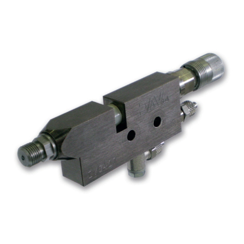
DAV TECH DA 400 EVO Product manual
DAV TECH
DAV TECH DA 400 Product manual
DAV TECH
DAV TECH DA 400 EV Product manual
DAV TECH
DAV TECH DAS 50N Product manual
DAV TECH
DAV TECH DAS 30 Product manual
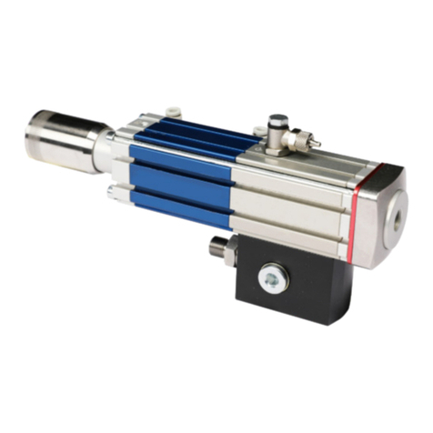
DAV TECH
DAV TECH DAV 150 Product manual
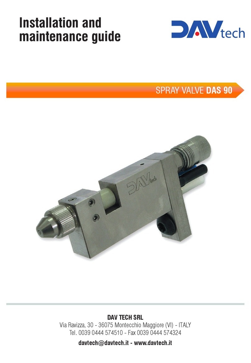
DAV TECH
DAV TECH DAS 90 Product manual
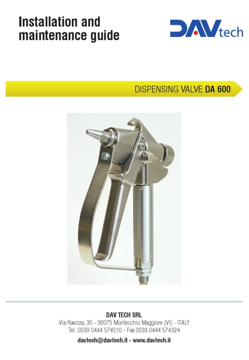
DAV TECH
DAV TECH DA 600 Product manual
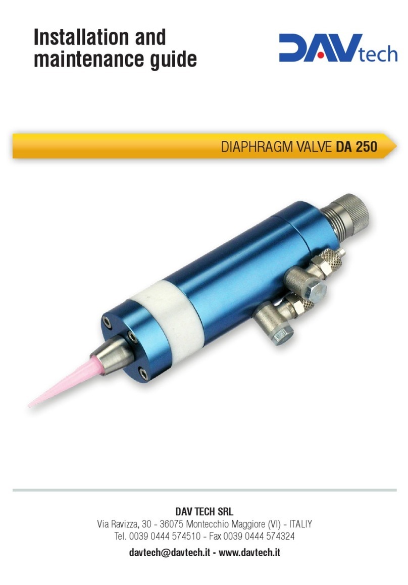
DAV TECH
DAV TECH DA 250 Product manual
Popular Control Unit manuals by other brands
REMKO
REMKO Smart WP MANAGER operating manual

Bosch
Bosch Rexroth ctrlX CORE manual

hager
hager RTN710X manual
Rockwell Automation
Rockwell Automation Bulletin 193 E1 PLUS Application and Installation

Genebre
Genebre 2103 Installation, operation and maintenance manual
Swegon
Swegon TBLZ-1-66 installation instructions

