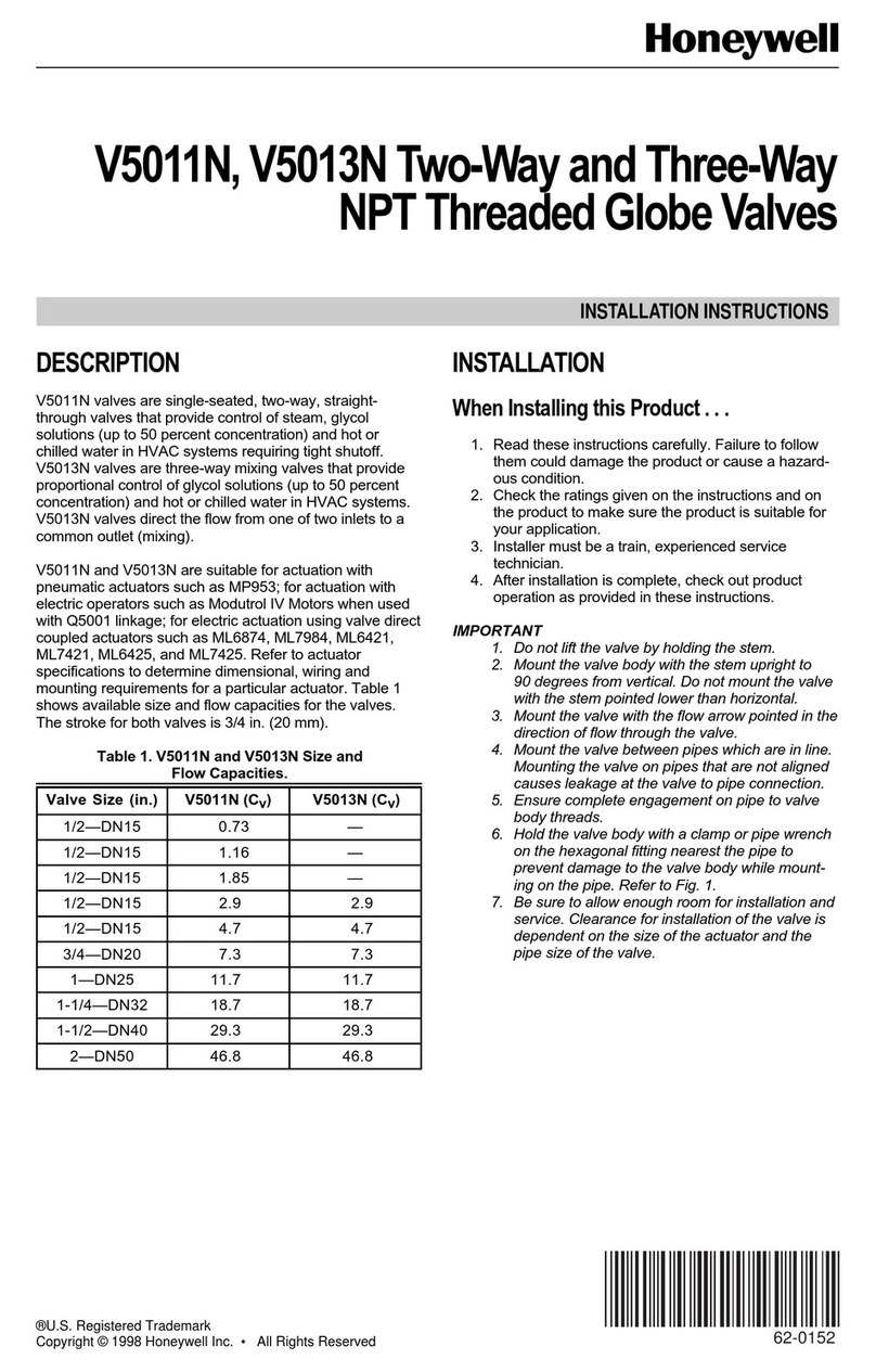
DAV TECH DAV 150 Product manual

VOLUMETRIC DISPENSING VALVE DAV 150
DAV TECH SRL
Via Ravizza, 30 - 36075 Montecchio Maggiore (VI) - ITALIA
Tel. 0039 0444 574510 - Fax 0039 0444 574324
Installation and
maintenance guide

Indice generale degli argomenti
1 INTRODUZIONE pag. 3
1.1 Il Manuale
1.2 Garanzia
1.3 Ricevimento merce
2 DESCRIZIONE TECNICA pag. 3
2.1 FunzionI delle valvole
2.2 Specifiche tecniche
3 AVVERTENZE pag. 4
4 FORMAZIONE DEL PERSONALE pag. 8
5 RILEVAZIONE DI ERRORI ED ELIMINAZIONE DEI GUASTI pag. 8
6 MANUTENZIONE pag. 8
7 ESPLOSO E COMPONENTI pag. 10
7.1 Componenti
Installation and maintenance guide

pag.3
1 INTRODUCTION
1.1 The manual
The user guide is the document that accompanies the valve from the time of its construction and throughout the period of
use, it is therefore an integral part of the valve. It requires reading the manual before taking any action involving the valve. The
manual must be readily available for use by staff and maintenance of the valve. The user and the attendant use are required
to know the contents of this manual.
Reproduction of any part of this manual, in any form, without the express written permission of DAV Tech. The text and
illustrations in this manual are not binding, the DAV tech reserves the right, at any time and without notice, the right to make
any changes to improve the product or for reasons of character manufacturing or commercial.
1.2 Warranty
The warranty is valid for a period of 12 months from the date of commissioning and no later than 15 months from the
date delivery. The interventions carried out during the warranty period does not extend in any way the validity period of the
guarantee. The seller is not liable for defects caused by normal wear of parts which by their nature are subject to wear.
1.3 Goods receiving
The original configuration of the valve must never be changed.
Upon receipt of the goods, check that:
• The packaging is intact
• The exact correspondence of the material ordered.
2 TECHNICAL DESCRIPTION
2.1 Valve operation
The DAV 150 volumetric dispensing valve is a pneumatically operated component designed for precision dispensing of low
viscosity lubricants.
The exchange of the pneumatic supply, at a pressure equal to or greater than 6 bar, will lead to the emptying of the volumetric
chamber and the relative outflow of a constant and adjustable quantity of fluid.
2.2 Technical specification
Model DAV 150
Configuration Standard (assembly block)
Dispensing range [mm³] 3-200
Dispensing range [ml] 0,003-0,200
Weight [kg] 0,78
Connection (medium intake) inside thread G 1/8”
Connection (medium discharge/pressure discharge) inside thread G 1/8”
Optimal medium intake working pressure [bar] 1-6
Max. medium intake working pressure [bar] 12
Connection (compressed air) inside thread M5 for hose ø4 mm
Bleed hose connection ø 4 mm
Min./max. pneumatic operating pressure [bar] 5/7
Optimal pneumatic operating pressure [bar] 6
Compressed air quality ISO 8573-1:2020 [6:4:4]
VOLUMETRIC DISPENSING VALVE DAV 150

Safety warnings
Read this operating manual carefully to familiarise yourself with the safe and efficient operation of the product. Retain
this manual as a reference. This operating manual contains important provisions and information for the safe and proper
operation of the product. It is also intended to help operating and maintenance personnel to minimise hazards, repair costs
and downtime, and to improve the reliability and service life of the product. It is therefore important to ensure access to this
document at all times for any person assigned to the care of the product.
Intended use
The product may be used only under the intended operating conditions. Any other or further use is considered improper use.
The manufacturer is not liable for damage due to improper use. Intended use includes:
• Observing and complying with all notices and warnings in this operating manual.
• Performing all inspection and maintenance work.
Obligations of the operating company
The person responsible for the safety of the product has to ensure that:
• Only qualified personnel is assigned to work on the product.
• The operating manual is always available to said personnel during all work, and the personnel is obliged to consistently
follow it.
• The accident prevention rules and regulations applicable for the place of use are observed, and the prescribed maintenance
and repair work is carried out.
Fundamental safety instructions
The following must be observed for the safe handling and trouble-free operation of this product:
• Using the product for other than its intended use is prohibited.
• No changes may be made to the product.
• A safe operating state has to be maintained at all times. Upon request, we can provide equipment training to bring your
personnel up to the required level of knowledge.
• Disconnect the product from all energy sources prior to any maintenance work.
• All lines, hoses and screw connections must be inspected for leaks and externally visible damage at regular intervals.
Damage has to be repaired promptly by qualified personnel; damaged parts must be replaced with original parts.
• Protective devices may only be removed after the product is standing still and has been secured to prevent restarting.
• All safety equipment must be installed properly and has to be fully functional each time before the product is put into use.
• The required personal protective equipment must be provided by the operating company.
• All safety and protective devices have to be inspected regularly.
WARNING OF A HAZARD
Warnings are information about hazards that may lead to physical injury and/or damage to property.
NOTE
Notices provide valuable information and user tips.
RISK OF CRUSHING
Warning of danger of crushing.
ENVIRONMENTAL HAZARD
Proper disposal of the various materials protects the environment.
3. WARRANTY
Installation and maintenance guide

pag.5
Hazards due to hydraulic and pneumatic energy
Depending on the version, the product works with high hydraulic or pneumatic pressure (see technical data). Sections of the
system that need to be opened, such as pressure lines, valves or loads, have to be de-pressurised before the start of repairs.
No residual pressure is permitted to remain.
Hazards due to lubricants
The safety notices and instructions of the lubricant manufacturer have to be observed and followed. The manufacturer of this
product disclaims any liability for incidents resulting from failure to follow the regulations,instructions and recommendations
of the lubricant manufacturer.
Maintenance, upkeep and troubleshooting
• Prescribed adjustment and maintenance tasks according to the maintenance schedule have to be carried out in a timely manner.
• Inform the operating personnel about adjustment and maintenance work.
• The master switch (if any) has to be turned off.
• Disconnect the energy supply from the network and secure it against unintentional reconnection.
• Pneumatic and/or hydraulic systems must be de-pressurised.
• Check all threaded connections and fittings for tightness.
• All safety devices and operating functions have to be checked after completion of the work.
Warranty and liability
Warranty and liability claims for personal injury and damage to property are excluded when they are due to one or more of
the following causes:
• Improper use of the product.
• Work carried out by other than qualified personnel.
• Improper transportation, storage, assembly, commissioning, operation and maintenance of the product.
• Failure to observe the information in the operating manual regarding safety, transportation, storage, assembly,
commissioning, operation, maintenance and setup of the product.
• Operating the product with defective protective devices or improperly installed or non-functional safety and protective
devices.
• Structural changes to the product.
• Changing the compression ratios for pressure protection, and operating at pressures higher than intended for the product.
• Insufficient monitoring of machine components that are subject to wear.
• Improper repairs and using third-party components.
Safety notices for using the product
All parts and assemblies were developed and built according to recognised safety-related rules. Nevertheless, improper use or
handling may result in hazards for the user or third parties or damage to the product or other material assets.
The product may only be used:
• According to the intended use.
• In safe and proper technical condition.
SPECIFIC HAZARDS
Electrical energy
Hydraulic and pneumatic energy
ELECTRICAL VOLTAGE
Warning of electrical hazards that may lead to physical injury and/or damage to property.
CAUTION
The product always has to be shut off prior to all work.
ENVIRONMENTAL HAZARD The various materials/liquids have to be handled properly and disposed of
separately according to the respective applicable national regulations.
HYDRAULIC AND PNEUMATIC SYSTEMS
Warning of hydraulic and pneumatic hazards that may lead to physical injury and/or damage to property.
VOLUMETRIC DISPENSING VALVE DAV 150

Safety warranty
Read the instructions carefully to familiarize yourself with the safe and efficient operation of this product.
Keep this manual for future reference. These operating instructions contain important instructions and warnings for the safe
and correct operation of the product. They will also assist operational and maintenance personnel
maintenance in order to minimize hazards, repair costs and downtime, increasing the reliability and life of the product.
Therefore, it is important to ensure that all persons entrusted with product assistance are consulted at all times by this
document.
Product description - Purpose
The needle metering valve is used for dispensing low viscosity lubricants.
Labelling
The needle metering valve is labelled according to the model code (Figure A/No. 6).
Functionality
Due to the compressed air connections, the needle metering valve can be controlled externally via a 5/2-way valve (Figure D/
No. 10). This initiates dispensing in the hydraulic section, provided the needle metering valve is connected to an active pump.
The desired dispensing volume is continuously adjustable in the range from 3 mm3 to 200 mm3 with the adjustment screw
(Figure A/No. 5). A locking screw (Figure A/No. 4) is provided to retain the set quantity. The vent with hose connection (Figure
B/No. 7) permits the clean discharge of the medium.
Description of the pictured components (Figures A – D)
1 Medium discharge
2 Connection block
3 Medium intake
4 Locking screw
5 Dispensing screw
6 Type key
7 Bleed screw
8 Pneumatics connection
9 Mounting holes
10 5/2-way valve (Not included in the scope of delivery)
Assembly/installation
The product has to be set up or installed at the intended installation site under consideration of the following conditions.
• The applicable legal provisions on site have to be clarified and compliance must be assured.
• The available space has to be clarified prior to installation/setup of the product in order to ensure ongoing safe
operation for the personnel and product. The product has to be set up/installed so that ongoing safe operation is
assured.
• The product may only be set up and put into operation by qualified personnel with corresponding special training.
• The product is designed for use in rooms protected against the effects of weather (industry standard).
• Operation and storage in aggressive, excessively damp environments or outdoors may lead to corrosion damage.
• The valves can be installed in any position.
• The distance to the application surface depends on the desired application pattern.
Installation and maintenance guide

pag.7
Commissioning
• The lubricant supply hose must be filled with lubricant before connecting a needle metering valve (bleeding process).
• Then connect the supply hose to the medium input (Figure B/No. 3).
• Connect control air to the pneumatic connections (Figure B/No. 8).
• The maximum flow volume has to be adjusted during commissioning. In order to do so, loosen the locking screw (Figure A/
No. 4) and turn the dispensing screw (Figure A/No. 5) to the rear stop (display: 100 %).
• Open the bleed screw (Figure B/No. 7) until medium is discharged, then close the screw again immediately.
• For clean bleeding, a pneumatic hose can be connected to the bleed screw to cool the air/medium mixture.
• Adjust the dispensing volume for application by changing the
- dispensing volume using the dispensing screw (Figure A/No. 5)
- medium pressure (if applicable with the optional material pressure regulator or directly with the pump pressure)
- control air pressure (changes the dispensing time) until the application quality is correct.
Operation
• As a rule, the needle metering valve works with a control air pressure of 6 bar and material pressure of 1 – 6 bar. For
consistent application, ensure that the air and lubricant supply is constant without pressure fluctuations and the lubricant
viscosity does not change.
• Depending on the application case, the control air pressure has to be adjusted to the switching frequency that is used on the
one hand and the higher or lower material pressure on the other hand.
Packaging, transportation and storage
DAV Tech prepares the product for transportation to the respective initial destination. The packing unit must not be subjected to
excessive strain. Protect the packaging and contents against exposure to moisture. Keep the temperature between -20 °C and
+40 °C during transportation.
Transport damage
If transport damage is found during the receiving inspection, proceed as follows:
• Notify the carrier (shipper etc.)
• Record the damage
• Inform the supplier
Storage
Operation and interim storage in aggressive, damp environments or outdoors may lead to corrosion and other damage.
Maintain the storage temperature in the range of -20 °C to +40 °C.
• Re-tighten the locking screw (Figure A/No. 4).
CAUTION
Do not aim the jet at people. Wearing eye protection is highly recommended.
Depending on the material conveying pressure, the spraying process may be accompanied by noise.
Hearing protection should be worn if needed.
CAUTION
Do not aim the jet at people. Wearing eye protection is highly recommended. Depending on the material
conveying pressure, the spraying process may be accompanied by noise. Hearing protection should be worn
if needed.
VOLUMETRIC DISPENSING VALVE DAV 150

FAULT POSSIBLE CAUSE REMEDY
The needle metering
valve switches but no
lubricant is ejected
The feed pump is not supplying
lubricant
Consult the operating manual for the
feed pump
The needle metering
valve switches but no
lubricant is ejected
Material pressure too low Increase pump pressure
The dispensing valve is
leaking
The control air pressure/counter-
pressure of the spring is too low
Increase the control air pressure,
reduce the material pressure, install
a stronger spring
The dispensing valve is
leaking Defective seals Replace seals
Air in the system Air pockets in the grease container
Air pockets in the hoses
Loosen supply hose. Bleed system.
Reconnect supply hose.
Leaky valve Defective seals Replace seals
Irregular dispensing No constant grease and air Upstream installation of optional material
pressure regulator MDR
WHEN WHAT HOW WHO
Weekly Check valve for tightness
Visual Qualified
personell
Weekly Check all threaded connections and fittings
for leaks
Monthly Check seals for damage and wear
Annually Complete maintenance Dismantle, clean and
replace seals
TRAINING OF PERSONNEL
Only trained and instructed personnel who have read and understood all points in the operating instructions may work on
the product. The personnel must also be able to control the operating states, and identify and implement the interrelated
safety aspects. Personnel in training may only work on the product under the supervision of qualified personnel.
5 TROUBLESHOOTING, FAULT RESOLUTION
6 MAINTENANCE
Needle metering valves are precision instruments that are not susceptible to faults, given proper handling, and operate
largely without maintenance, assuming that the application material is generally processed in clean condition, not
contaminated by foreign particles. We recommend the following maintenance intervals to optimise the service life:
The specified maintenance intervals are for single shift operation. Maintenance has to be carried out more often
depending on the field of application, medium and in case of operation in more than one shift.
CAUTION
All of the faults described below may only be resolved by trained, qualified personnel.
CAUTION All work on the system is basically only to be carried out when it is at a standstill. The pneumatic
and hydraulic systems have to be de-pressurised. The pressure gauges have to show 0 bar.
Installation and maintenance guide

pag.9
Shutdown
Short interruptions:
In case of short interruptions (15 minutes or more), the product has to be shut off and completely de-pressurised.
No residual pressure is permitted to remain in the system.
Longer interruptions:
For longer interruptions (more than one day), note the following points:
• The main switch/pump must be turned off
•No residual pressure is permitted to remain in the system (check the indicators)
Drawings and replacement parts
Accessories, drawings, dimension sheets, data sheets and spare parts can be found at www.davtech.it.
Decommissioning and disposal
Observe the following points for decommissioning the product/taking it out of operation:
• Turn the master switch (if any) off
• Disconnect the mains plug (if any) from the network
• No residual pressure is permitted to remain in the system.
•The medium must be removed and properly disposed of.
© Publisher’s copyright
The duplication, translation or dissemination to third parties of this document requires the express consent of the
publisher.
Resale
This operating manual is part of the product and must be included in the scope of delivery in case of resale.
Customer service/support
DAV Tech Srl
Via Ravizza, 30 - 36075 Montecchio Maggiore - VICENZA - ITALY
Tel. +39 0444 574510
CAUTION Risk of accidents and environmental damage: Grease/oil on floors increa-ses the risk of
accidents. Properly dispose of grease/oil according to the applicable national regulations (special
waste).
ENVIRONMENTAL HAZARD The various materials/liquids have to be handled properly and disposed
of separately according to the respective applicable national regulations. Lubricants are considered
special waste.
VOLUMETRIC DISPENSING VALVE DAV 150

7. BREAKDOWN
28
39
37
30
38
40
47
27
35
10
33
36
19
21
20
13
29
20
14
46
9
49
314567
82
45 16 23 43 24
42
41
44
17
25 32
23
18
34
26
22
15
11
12
48
12
31
11
Installation and maintenance guide

pag.11
7.1 Components
POS. CODE QUANTITY DESCRIPTION
1011286 1 Gasket
2220900 1 O-Ring
3010025 1 Hydraulic component
4010026 1 Hydraulic component
5010105 1 Sleeve
6 206600 1 Ball
7221801 1 O-Ring
8010106 1 Case
9010031 1 Rod seal
10 001528 1 Magnet
11 430001 2 Screw plug
12 259300 2 Screw seal
13 001590 1 O-Ring
14 223500 1 O-Ring
15 005047 1 O-Ring
16 226800 1 O-Ring
17 227300 1 O-Ring
18 007775 1 O-Ring
19 005121 1 O-Ring
20 232100 2 O-Ring
21 353502 1 Slot ring
22 460002 1 Spring pin
23 007776 2 Ball
24 009349 1 Compression spring
25 007777 1 Compression spring
26 002213 2 Slot nut
27 634200 2 Connection pneumatic
28 411000 1 Cap nut
29 0001226 1 Socket head screw
30 8512700 1 Set screw
31 001593 4 Socket head screw
32 008608 1 Valve housing
33 011573 1 Needle
34 008602 1 Valve seat
35 008601 1 Piston
36 009071 1 lntermediate unit
37 010174 4 Socket head screw
38 001589 1 Pin
39 010173 1 Metering sleeve
40 008598 1 Metering screw
41 005068 1 Threaded plate C 3/C 4
42 008597 1 Housing
43 010108 1 Valve casing
44 008595 1 Connection piece
45 011292 1 Valve seat
46 008592 1 End piece
47 008591 1 Air cylinder
48 008590 1 Connection błock
49 008588 1 Grease cylinder
VOLUMETRIC DISPENSING VALVE DAV 150

Declaration of Incorporation
according to the EU Machinery Directive 2006/42/EG, Annex II, 1.B for partly completed machinery
Manufacturer:
DAV Tech Srl
Via Ravizza, 30 - 36075 Montecchio Maggiore
VICENZA - ITALY
Person residing within the Community authorised to compile the relevant technical documentation:
Andrea Grazioli
DAV Tech Srl
Via Ravizza, 30 - 36075 Montecchio Maggiore
VICENZA - ITALY
Description and identification of the partly completed machinery:
Type: Volumetric valves
Model: DAV 100, DAV 150, DAV 200, DAV 300, DAV 400, DAV 100 MAN, DAV 200 MAN, DAV 300 MAN, DAV 400 MAN.
It is also declared that the relevant technical documentation has been compiled in accordance with part B of
Annex VII.
It is expressly declared that the partly completed machinery the machinery fulfils all relevant provisions of the
following EU Directives:
• 2006/42/CE
• 2006/42/EG
• 95/16/EG
The manufacturer or his authorised representative undertakes to transmit, in response to a reasoned request by the
national authorities, relevant information on the partly completed machinery. This transmission takes place:
This does not affect the intellectual property rights!
Important note! The partly completed machinery may be put into service only if it was determined, where
appropriate, that the machinery into which the partly completed machinery is to be installed meets the provisions
of this Directive.
Andrea Grazioli
We reserve the right to modify at any time, without notice, the specifications, dimensions and weights in this manual.
The illustrations are not binding.
DAV TECH SRL Via Ravizza, 30 - 36075 Montecchio Maggiore (VI) - ITALY - Tel. 0039 0444 574510 - Fax 0039 0444 574324
Table of contents
Other DAV TECH Control Unit manuals
DAV TECH
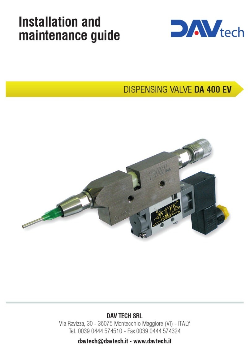
DAV TECH DA 400 EV Product manual
DAV TECH
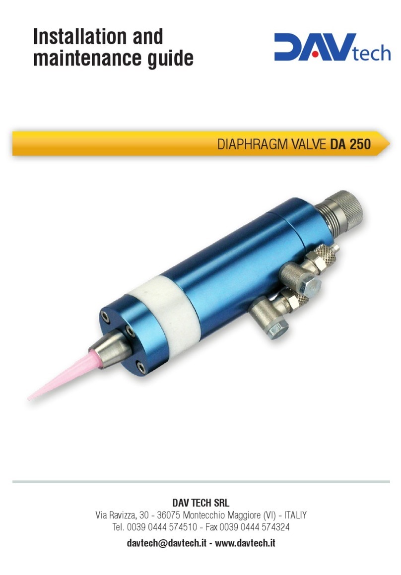
DAV TECH DA 250 Product manual
DAV TECH
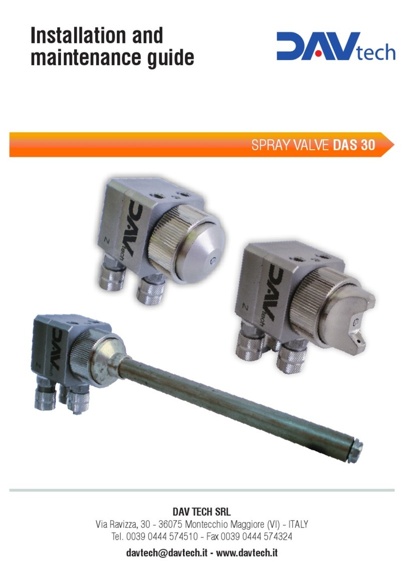
DAV TECH DAS 30 Product manual
DAV TECH
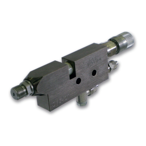
DAV TECH DA 400 Product manual
DAV TECH
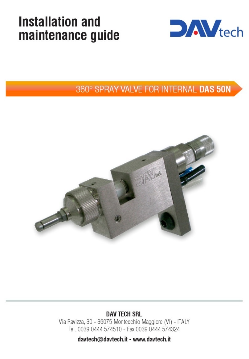
DAV TECH DAS 50N Product manual
DAV TECH
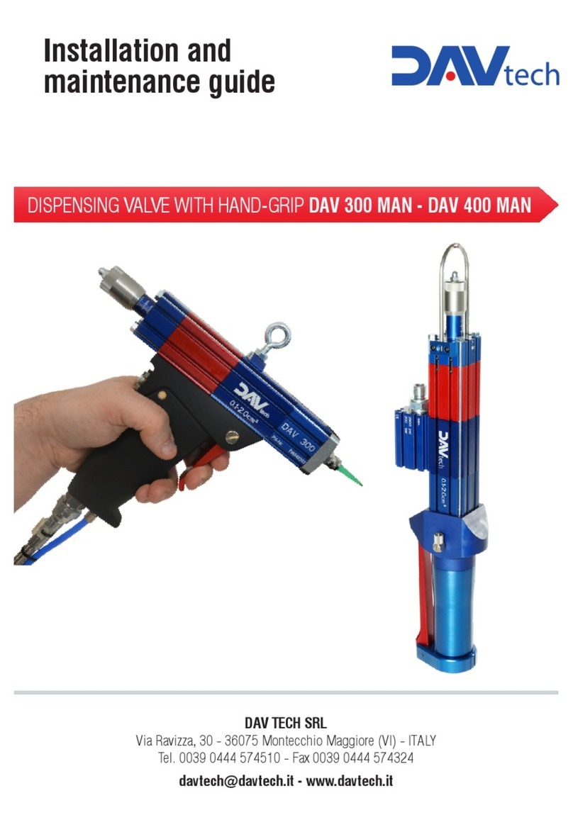
DAV TECH DAV 300 MAN Product manual
DAV TECH
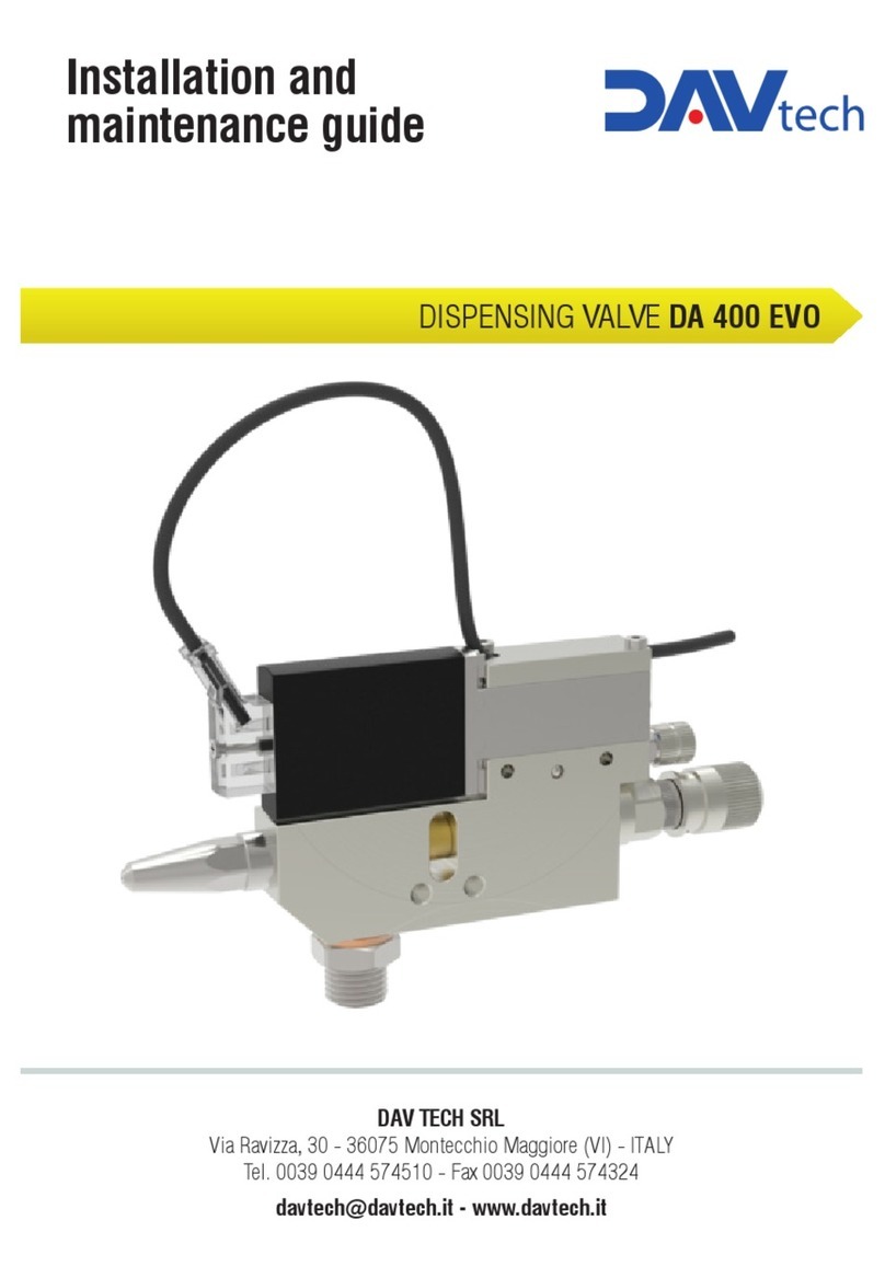
DAV TECH DA 400 EVO Product manual
DAV TECH
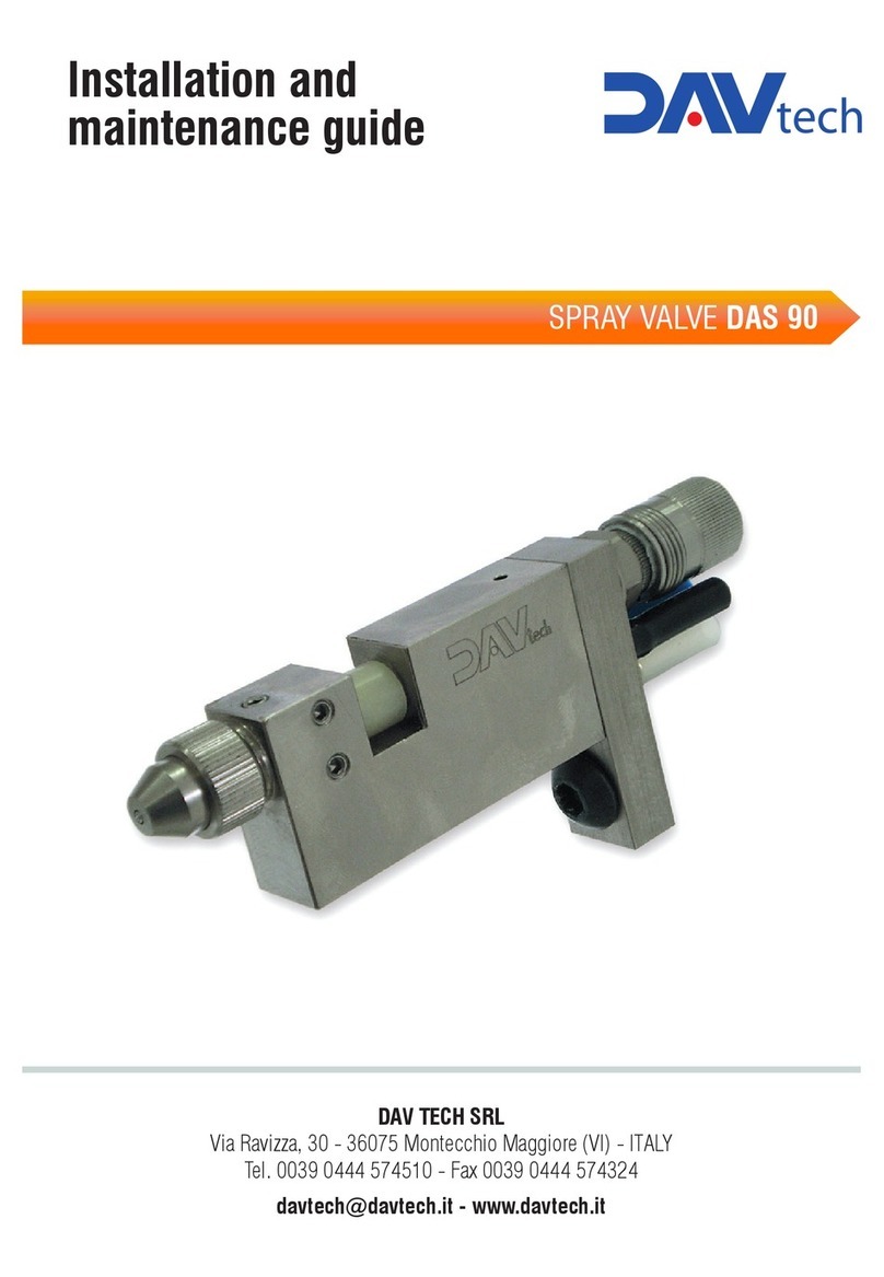
DAV TECH DAS 90 Product manual
DAV TECH
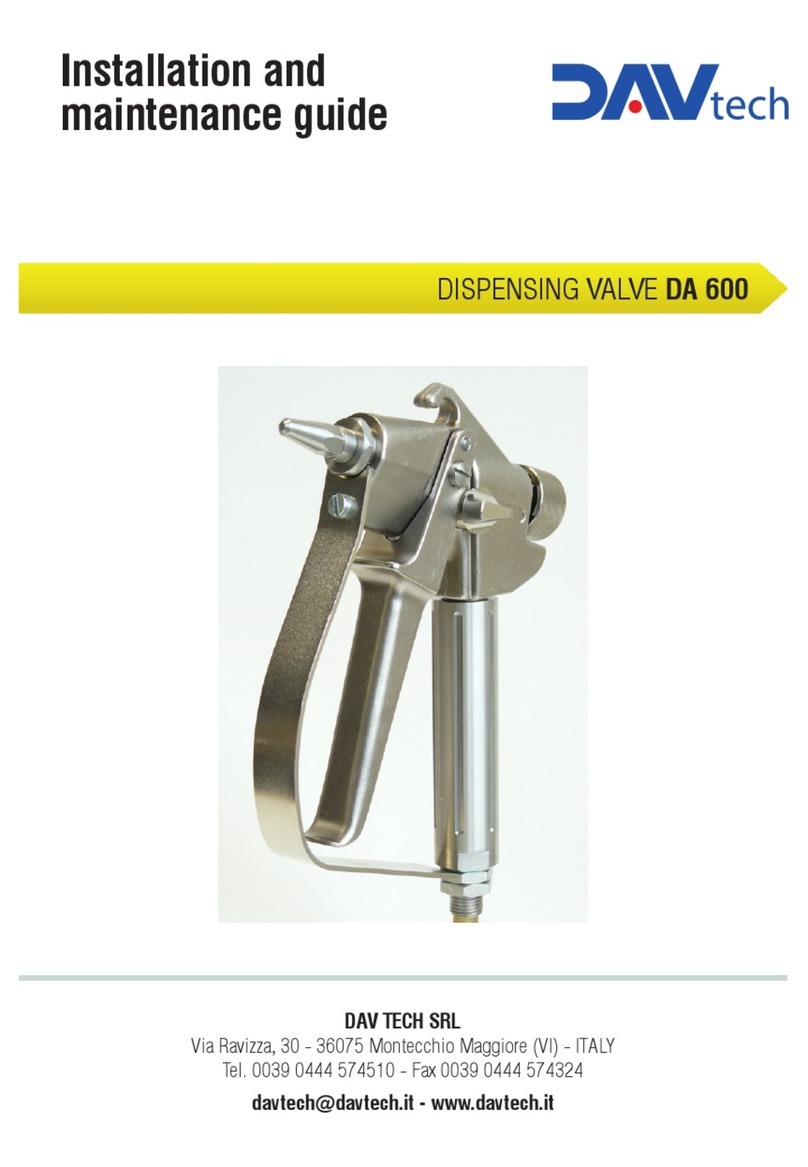
DAV TECH DA 600 Product manual
Popular Control Unit manuals by other brands
Eaton
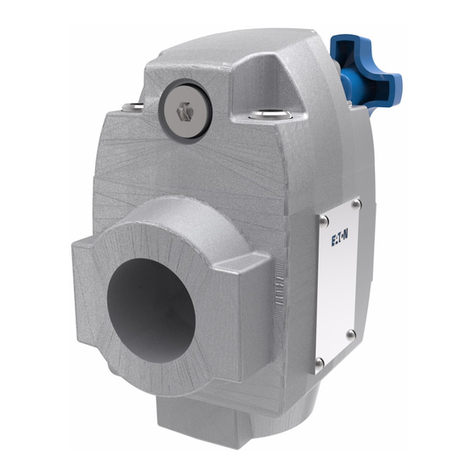
Eaton Vickers CG-03 Series Overhaul manual
resideo
resideo RV283P installation instructions

Nav TV
Nav TV MFT F-CAM installation manual
CALEFFI
CALEFFI 5231 Series Installation and commissioning manual
Panasonic
Panasonic CF-BAH0256U operating instructions

PRASTEL
PRASTEL UNIK2E-V2 Technical installation manual
