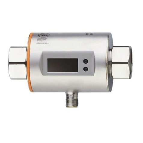
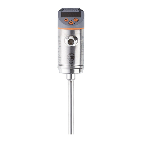
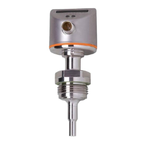
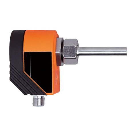
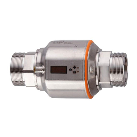
IFM SD26 Series User manual

Operating instructions
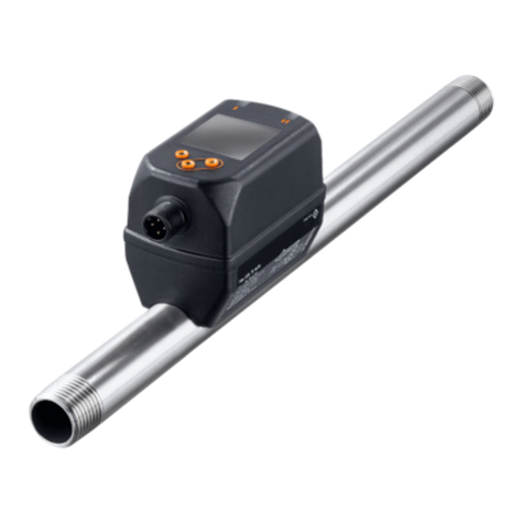
Flow meter compressed air / gases
SD25xx
SD26xx
SD55xx
SD56xx
SD65xx
SD66xx
SD85xx
SD86xx
SD95xx
80280071 / 00 01 / 2019
UK

2
Contents
1 Preliminary note���������������������������������������������������������������������������������������������������5
1�1 Symbols used ������������������������������������������������������������������������������������������������5
1�2 Warnings used�����������������������������������������������������������������������������������������������5
2 Safety instructions �����������������������������������������������������������������������������������������������6
3 Functions and features ����������������������������������������������������������������������������������������7
3�1 Pressure Equipment Directive (PED) ������������������������������������������������������������7
3�2 Applications ���������������������������������������������������������������������������������������������������7
4 Function���������������������������������������������������������������������������������������������������������������8
4�1 Processing of the measured signals��������������������������������������������������������������8
4�2 Switching output ��������������������������������������������������������������������������������������������9
4�3 Analogue output�������������������������������������������������������������������������������������������10
4�4 Consumed quantity monitoring [ImP] ����������������������������������������������������������12
4�4�1 Meter reading �������������������������������������������������������������������������������������12
4�4�2 Counter reset ������������������������������������������������������������������������������������12
4�4�3 Consumed quantity monitoring via pulse signals �������������������������������13
4�4�4 Consumed quantity monitoring via preset counter �����������������������������13
4�5 Measured value damping ����������������������������������������������������������������������������14
4�6 Low flow cut-off �������������������������������������������������������������������������������������������14
4�7 Simulation����������������������������������������������������������������������������������������������������14
4�8 Colour of the characters in the display ��������������������������������������������������������15
4�9 IO-Link ���������������������������������������������������������������������������������������������������������16
4�9�1 Additional functions via IO-Link ����������������������������������������������������������16
5 Installation����������������������������������������������������������������������������������������������������������16
5�1 Installation location ��������������������������������������������������������������������������������������17
5�2 Installation position ��������������������������������������������������������������������������������������17
5�2�1 Inlet and outlet pipe lengths����������������������������������������������������������������17
5�2�2 Orientation �����������������������������������������������������������������������������������������18
5�3 Installation in pipes ��������������������������������������������������������������������������������������18
6 Electrical connection������������������������������������������������������������������������������������������19
7 Operating and display elements ������������������������������������������������������������������������21
8 Menu������������������������������������������������������������������������������������������������������������������22
8�1 Process value display (RUN)�����������������������������������������������������������������������22
8�2 Main menu���������������������������������������������������������������������������������������������������23

3
UK
8�3 Extended functions (EF) ������������������������������������������������������������������������������24
8�4 Submenu OUT1�������������������������������������������������������������������������������������������25
8�5 Submenu OUT2�������������������������������������������������������������������������������������������27
8�6 Submenu CFG���������������������������������������������������������������������������������������������29
8�7 Submenus MEM, DIS ����������������������������������������������������������������������������������31
8�8 Submenus COLR, SIM ��������������������������������������������������������������������������������33
9 Set-up ����������������������������������������������������������������������������������������������������������������35
10 Parameter setting ��������������������������������������������������������������������������������������������35
10�1 Parameter setting in general ���������������������������������������������������������������������36
10�1�1 Select submenu��������������������������������������������������������������������������������36
10�1�2 Change to the process value display (RUN mode) ��������������������������36
10�1�3 Lock / unlock�������������������������������������������������������������������������������������36
10�1�4 Timeout���������������������������������������������������������������������������������������������37
10�2 Settings for volumetric flow monitoring������������������������������������������������������37
10�2�1 Limit monitoring OUT1 or OUT2 / hysteresis function ����������������������37
10�2�2 Limit monitoring OUT1 or OUT2 / window function ��������������������������37
10�2�3 Analogue signal volumetric flow OUT2���������������������������������������������37
10�3 Settings for consumed quantity monitoring �����������������������������������������������38
10�3�1 Quantity monitoring by pulse signal OUT1 or OUT2 ������������������������38
10�3�2 Quantity monitoring by preset counter OUT1 or OUT2 ��������������������38
10�3�3 Manual counter reset������������������������������������������������������������������������38
10�3�4 Time-controlled counter reset �����������������������������������������������������������38
10�3�5 Deactivation of the counter reset������������������������������������������������������38
10�3�6 Counter reset using an external signal ���������������������������������������������39
10�4 Settings for temperature monitoring ����������������������������������������������������������39
10�4�1 Limit monitoring OUT1 or OUT2 / hysteresis function ����������������������39
10�4�2 Limit monitoring OUT1 or OUT2 / window function ��������������������������39
10�4�3 Analogue signal temperature OUT2 �������������������������������������������������39
10�5 Settings for pressure monitoring����������������������������������������������������������������40
10�5�1 Limit monitoring OUT1 or OUT2 / hysteresis function ����������������������40
10�5�2 Limit monitoring OUT1 or OUT2 / window function ��������������������������40
10�5�3 Analogue signal pressure OUT2�������������������������������������������������������40
10�6 User settings (optional)������������������������������������������������������������������������������41
10�6�1 Standard display�������������������������������������������������������������������������������41
10�6�2 Standard unit of measurement for volumetric flow ���������������������������41
10�6�3 Standard unit of measurement for temperature��������������������������������41

4
10�6�4 Standard unit of measurement for pressure �������������������������������������41
10�6�5 Measured value damping �����������������������������������������������������������������42
10�6�6 Output logic ��������������������������������������������������������������������������������������42
10�6�7 Medium for SDx6xx units������������������������������������������������������������������42
10�6�8 Low flow cut-off���������������������������������������������������������������������������������42
10�6�9 Standard conditions��������������������������������������������������������������������������42
10�6�10 Zero-point calibration pressure�������������������������������������������������������42
10�6�11 Colour of the characters in the display �������������������������������������������43
10�6�12 Switch-on /switch-off delay �������������������������������������������������������������43
10�6�13 Error behaviour of the outputs ��������������������������������������������������������44
10�6�14 Restore factory setting��������������������������������������������������������������������44
10�7 Diagnostic functions ����������������������������������������������������������������������������������45
10�7�1 Read min/max values �����������������������������������������������������������������������45
10�7�2 Simulation�����������������������������������������������������������������������������������������45
11 Operation ���������������������������������������������������������������������������������������������������������46
12 Error correction������������������������������������������������������������������������������������������������46
13 Maintenance, repair and disposal��������������������������������������������������������������������48
14 Factory setting �������������������������������������������������������������������������������������������������49

5
UK
1 Preliminary note
Detailed instructions, technical data, approvals and other information via
the QR code on the unit / on the packaging or at www�ifm�com�
1.1 Symbols used
Instructions
> Reaction, result
[…] Designation of keys, buttons or indications
Cross-reference
Important note
Non-compliance may result in malfunction or interference�
Information
Supplementary note�
1.2 Warnings used
CAUTION!
Warning of personal injury�
Slight reversible injuries may result�

6
2 Safety instructions
• The device described is a subcomponent for integration into a system�
- The manufacturer is responsible for the safety of the system�
- The system manufacturer undertakes to perform a risk assessment and to
create a documentation in accordance with legal and normative requirements
to be provided to the operator and user of the system� This documentation
must contain all necessary information and safety instructions for the operator,
the user and, if applicable, for any service personnel authorised by the manu-
facturer of the system�
• Read this document before setting up the product and keep it during the entire
service life�
• The product must be suitable for the corresponding applications and environ-
mental conditions without any restrictions�
•
•
• If the operating instructions or the technical data are not adhered to, personal
injury and/or damage to property may occur�
• The manufacturer assumes no liability or warranty for any consequences
caused by tampering with the product or incorrect use by the operator�
• Installation, electrical connection, set-up, operation and maintenance of the unit
must be carried out by qualified personnel authorised by the machine operator�
• Protect units and cables against damage�

7
UK
3 Functions and features
The unit monitors the standard volume flow of compressed air in industrial use
and / or technical gases �
It detects the 5 process variables flow velocity, volumetric flow quantity, consumed
quantity, medium temperature and pressure�
All indications apply to standard volume flow to DIN ISO 2533, i�e� volume flow
at 1013 mbar, 15 °C and 0 % relative air humidity� The unit can be set to different
standard conditions �
This is a class A product� This product may cause radio interference in
domestic areas�
If required, take appropriate EMC screening measures�
3.1 Pressure Equipment Directive (PED)
The units comply with the Pressure Equipment Directive� They are designed for
stable gases of group 2 fluids and manufactured in accordance with sound engi-
neering practice�
3.2 Applications
SDx5xx
• Compressed air
SDx6xx
• Compressed air
• Argon (Ar)
• Carbon dioxide (CO2)
• Nitrogen (N2)
Selection of the medium to be monitored �

8
4 Function
• The volumetric flow is monitored by a calorimetric measuring system, the
measured signals are evaluated by the electronics�
• The unit detects the pressure and the media temperature of the volumetric flow
as additional process values�
• The unit features an IO-Link interface
• The unit displays the current process values�
• The unit has many self-diagnostic options�
• A simulation mode allows simplified set-up of the sensor�
4.1 Processing of the measured signals
The unit generates 2 output signals according to the parameter setting:
OUT1: 7 selection options
- switching signal for volumetric flow quantity limit
- switching signal for temperature limit
- switching signal for pressure limit
- switching signal for preset counter
- pulse signal for quantity meter
- IO-Link
- OFF (output switched to high impedance)
OUT2: 10 selection options
- switching signal for volumetric flow quantity limit
- switching signal for temperature limit
- switching signal for pressure limit
- switching signal for preset counter
- switching signal for quantity meter
- analogue signal for volumetric flow quantity
- analogue signal for temperature
- analogue signal for pressure
- input for external counter reset signal (InD)
- OFF (output switched to high impedance)

9
UK
4.2 Switching output
OUTx changes its switching status if it is above or below the set switching limits
(flow, temperature or pressure)� Hysteresis or window function can be selected�
Example of volumetric flow monitoring:
Hysteresis function Window function
SP
rP FL
FH
SP = set point
rP = reset point
HY = hysteresis
Hno / Fno = NO (normally open)
FH = upper limit
FL = lower limit
FE = window
Hnc / Fnc = NC (normally closed)
When the hysteresis function is set, the set point (SP) is defined first and
then the reset point (rP) which must have a lower value� If only the set point
is changed, the reset point is changed automatically; the difference remains
constant�
When set to the window function, the upper limit value (FH) and the lower
limit value (FL) have a fixed hysteresis of 0�25 % of the final value of the
measuring range� This keeps the switching status of the output stable if the
volumetric flow varies slightly�

10
4.3 Analogue output
The unit provides an analogue signal that is proportional to the volumetric flow
quantity, the medium temperature or the pressure�
Within the measuring range the analogue signal is 4���20 mA�
The measuring range is scalable:
• [ASP2] determines at which measured value the output signal is 4 mA�
• [AEP2] determines at which measured value the output signal is 20 mA�
Minimum distance between [ASP2] and [AEP2] = 20 % of the final value of
the measuring range�
If the measured value is outside the measuring range or in the event of an internal
error, the current signal indicated in Fig� 1 is provided�
For measured values outside the display range or in case of a fault, messages are
displayed (cr�UL, UL, OL, cr�OL, Err; )�
The analogue signal in case of a fault is adjustable :
• [FOU] = On determines that the analogue signal goes to the upper final value
(21�5 mA) in case of an error�
• [FOU] = OFF determines that the analogue signal goes to the lower final value
(3�5 mA) in case of an error�
• [FOU] = OU defines that in case of a fault the analogue signal reacts as defined
by the current parameters�

11
UK
MEWMAW AEPASP
Q [% MEW]
[°C]T -24 -10 60 74 78-31
[°F]-11 14 140 161 172-24
[bar]P -1 0 16 20
1201000 130
4
3,8
3,5FOU=OFF
20
20,5
21,5
[mA]
FOU=On
1
2
6
cr�UL UL OL cr�OL
3
4
5
Fig� 1: Characteristics of the analogue output according to the standard IEC 60947-5-7�
1
analogue signal
2
measured value (volumetric flow, temperature or pressure)
3
detection zone
4
display range
5
measuring range
6
scaled measuring range
Q: flow
P: pressure
T: temperature
MAW: initial value of the measuring range for non-scaled measuring range (With setting of a
low-flow cut for Q: signal output starting at MAW + LFC �)
MEW: final value of the measuring range for non-scaled measuring range
ASP: analogue start point with scaled measuring range
AEP: analogue end point with scaled measuring range
UL: below the display range
OL: above the display range
cr�UL: below the detection zone (error)
cr�OL: above the detection zone (error)

12
4.4 Consumed quantity monitoring [ImP]
The unit has an internal quantity meter (totaliser)� It continuously sums up the
consumed quantity and provides this process value both on the display and via
the IO-Link interface�
Pulse signals or a switching signal (preset counter) can be used to monitor the
consumed quantity�
4.4.1 Meter reading
The current quantity meter count can be indicated �
In addition, the value before the last reset is saved� This value and the time since
the last reset can also be displayed �
The meter saves the totalled volumetric flow quantity every 10 minutes�
After a power failure this value is available as the current meter reading� If a
time-controlled reset is set, the elapsed time of the set reset interval is also
saved� So the possible data loss can be at most 10 minutes�
4.4.2 Counter reset
There are different ways to reset the quantity meter�
If the quantity meter is not reset by applying one of the above-mentioned methods,
an automatic reset takes place when the maximum volumetric flow quantity that
can be displayed is exceeded (overflow)�
OUT1 and OUT2 cannot be used simultaneously for the consumed quantity
monitoring�
The accuracy of the consumed quantity measurement depends on the
accuracy of the flow measurement�

13
UK
4.4.3 Consumed quantity monitoring via pulse signals
Every time the flow rate set with [ImPS] has been reached (pulse value), the
output provides a pulse signal�
OUT1 and OUT2 cannot be used simultaneously for the pulse output�
4.4.4 Consumed quantity monitoring via preset counter
When the flow rate set under [ImPS] has been reached, the output provides a
switching signal�
The setting of the parameter [rTo] defines if the volumetric flow quantity has to
be reached irrespective of the time (1) or within a set time (2) so that the output
switches:
[rTo] Output Counter reset
(1)
OFF
• The output switches when the
volumetric flow quantity set with
[ImPS] has been reached�
• The output remains switched
until the counter reset�
• The preset counter is only reset
- when a manual reset is made
or
- when the maximum display
range has been exceeded
(overflow)�
(2)
1, 2,��� h
1, 2,��� d
1, 2,��� w
• The output switches only when
the volumetric flow quantity set
with [ImPS] is reached within
the set time�
• The output remains switched
until the counter reset�
• If the output is not switched, the
preset counter is automati-
cally reset when the time has
elapsed and the count starts
again -
trolled counter reset)
• If the output is switched, the
preset counter is only reset�
- when a manual reset is made
or
- when the maximum display
range has been exceeded
(overflow)�

14
4.5 Measured value damping
The damping time [dAP�F] und [dAP�P] allows to set after how many seconds the
output signal has reached 63 % of the final value if the flow value / the pressure
value changes suddenly� The set damping time stabilises the switching outputs,
the display and the process value transfer via the IO-Link interface�
data)�
The signals [UL] and [OL] are defined under consideration of the damping
time�
4.6 Low flow cut-off
With the function low flow cut-off [LFC] it is possible to suppress small volumet-
ric flow quantities� Flows below the LFC value are evaluated by the sensor as
standstill (Q = 0)�
4.7 Simulation
With this function, the process values flow, temperature, pressure and meter read-
ing of the totaliser are simulated and their signal chain is reviewed�
When the parameters cr�UL, UL, OL und cr�OL are set, the process values that
lead to an error message or warning can be simulated �
When the simulation is started, the values of the totaliser are frozen and the
simulated totaliser is set to 0� The simulated flow value then has an effect on the
simulated totaliser� When the simulation is ended, the initial totaliser values are
restored�
The simulation does not have any effect on the currently existing process
values� The outputs operate as previously set�
During the simulation the original totaliser value remains saved without any
changes even if there is a real flow�
During the simulation operation, no error message of the currently real
application is available� They are suppressed by the simulation�

15
UK
4.8 Colour of the characters in the display
The colour of the characters in the display can be set via the parameter [coL�x]:
• Permanent definition of the display colour:
- bk/wh (black/white)
- yellow
- green
- red
• Colour change from red to green or vice versa (Fig� 2):
- r-cF (red display colour between the limits cFL���cFH)
- G-cF (green display colour between the limits cFL���cFH)
cFL cFH
MAW MEW
cFL = lower limit
cFH = upper limit
MAW = initial value of the measuring range
MEW = final value of the measuring range
Fig� 2: Colour setting window function
The limits can be freely selected within the measuring range and are inde-
pendent of the output function set for OUT1 and OUT2�

16
4.9 IO-Link
This unit has an IO-Link communication interface which enables direct access to
process and diagnostic data� In addition it is possible to set the parameters of the
unit while it is in operation� Operation of the unit via an IO-Link interface requires
an IO-Link master�
With a PC, suitable IO-Link software and an IO-Link adapter cable communication
is possible when the system is not in operation�
The IODDs necessary for the configuration of the unit, detailed information about
process data structure, diagnostic information, parameter addresses and the
necessary information about the required IO-Link hardware and software can be
found at www�ifm�com�
4.9.1 Additional functions via IO-Link
The following functions are only available via the IO-Link interface by means of a
parameter setting software:
Flash on /
Flash off
Standard command for localising the sensor in the system�
When activated:
> switching status indicating LEDs are flashing
> display: "IO-Link" (green, flashes)
5 Installation
CAUTION!
If the medium temperature is above 50 °C (122 °F), parts of the
housing can increase in temperature to over 65 °C (149 °F)�
> Risk of burns�
Protect the housing against contact with flammable substances
and unintentional contact�
Apply the supplied warning label to the sensor cable�
Ensure that the system is free of pressure during installation�
The rules and regulations for the installation and operation of com-
pressed air equipment must be observed�

17
UK
5.1 Installation location
Install the unit downstream of the cold dryer�
Install the unit near the load�
The unit can be installed downstream of a maintenance unit�
If oil is used for the loads: install the unit upstream of the oiler�
5.2 Installation position
5.2.1 Inlet and outlet pipe lengths
Structures in the pipe, bends, valves, reducing pieces and the like affect the
function of the unit�
Adhere to the distances between sensor and interference:
Interference Distance to the sensor
changes to the pipe diameter 10 x pipe diameter
90° elbow 10 x pipe diameter
two 90° elbows, one plane 15 x pipe diameter
two 90° elbows, two planes 25 x pipe diameter
valve, slide 40 x pipe diameter
Shut-off valves and control devices are not allowed directly in front of the
unit�

18
5.2.2 Orientation
1 2 3
4
Fig� 1: Orientation of the pipe length and the unit
1: pipe length vertical, unit any
2: pipe length horizontal, unit vertical
3: pipe length right, unit on side
4: avoid: pipe length left, unit on side
5.3 Installation in pipes
Fit the unit in the pipe in accordance with the flow direction (arrow on the unit):
IN OUT
Tighten both adapters in opposite direction by applying the defined tightening
torque:

19
UK
Type Tightening torque
SD5xxx 50 Nm
SD6xxx, SD8xxx 100 Nm
SD2xxx, SD9xxx 150 Nm
6 Electrical connection
The device must be connected by a qualified electrician� Voltage supply
according to EN 50178, SELV, PELV�
Disconnect power�
Connect the unit as follows:
BN
WH
BK
BU
4
1
3
2OUT2
L+
L
OUT1
Colours to DIN EN 60947-5-2
BK: black; BN: brown; BU: blue; WH: white
Pin Connection
4
(OUT1)
• switching signal for volumetric flow
• switching signal for temperature
• switching signal for pressure
• switching signal for preset counter
• pulse signal for quantity meter
• IO-Link
• OFF
2
(OUT2/InD)
• switching signal for volumetric flow
• switching signal for temperature
• switching signal for pressure
• switching signal for preset counter
• pulse signal for quantity meter
• analogue signal for volumetric flow
• analogue signal for temperature
• analogue signal for pressure
• input for external counter reset signal (InD)
• OFF

20
Circuit examples:
2 x positive switching 2 x negative switching
L
L+
3 BU
4 BK
2 WH
1 BN
L
L+
3 BU
4 BK
2 WH
1 BN
1 x positive switching / 1 x analogue 1 x negative switching / 1 x analogue
L+
L
3 BU
4 BK
2 WH
1 BN
L+
L
3 BU
4 BK
2 WH
1 BN
This manual suits for next models
8
Table of contents
Other IFM Measuring Instrument manuals
Popular Measuring Instrument manuals by other brands

Rapsodo
Rapsodo HITTING 2.0 quick start guide

Smart Process
Smart Process Eastron SDM210-DR user manual

2B Technologies
2B Technologies Ozone Monitor 106-L Operation manual

HP
HP 204C Operating and service manual

SEFAR
SEFAR Tensocheck 100 Instructions for use

Fuji Electric
Fuji Electric ZPA instruction manual