Dea REV Series User manual

Downee
Tech Support
Telephone: 1800 241 733
Tech Support Hotline: 0419 599 982
Email: techsupport@downee.com.au
Operating Instructions
REV

19
REV
Electromechanical operators
for sliding gates
Operating instructions and warnings
Index
1Warnings Summary 19 7Advanced Programming 29
2Product Description 20 8Messages shown on the Display 31
3Technical data 20 9Start-up 31
4Installation and Assembly 21 9.1 Installation Test 31
5Electrical Connections 9.2 Unlocking and manual operation 31
5.1 Electrical Connections
for 24V models 22 10 Maintenance 32
5.2 Electrical Connections
for 230V models 24 11 Product Disposal 32
6Standard Programming 26
Product Conformity
DEA System guarantees the conformity of the product to European Directives 2006/42/CE regarding “machinery safety”,
2004/108/CE“electromagneticcompatibility”and2006/95/CE“lowvoltageelectricalequipment”.SeeDeclaration of Incorpo-
ration.
1 WARNINGS SUMMARY
Readthesewarningscarefully;failuretorespectthefollowingwarningsmaycauserisksituations.
WARNING Usingthisproductunderunusualconditionsnotforeseenbythemanufacturercancreatesituationsofdanger,and
forthisreasonalltheconditionsprescribedintheseinstructionsmustberespected.
WARNINGDEASystemremindsallusersthattheselection,positioningandinstallationofallmaterialsanddeviceswhichmake
upthecompleteautomationsystem,mustcomplywiththeEuropeanDirectives2006/42/CE(MachineryDirective),2004/108/CE
(electromagneticcompatibility),2006/95/CE(lowvoltageelectricalequipment).Inordertoensureasuitablelevelofsafety,besides
complyingwithlocalregulations,itisadvisabletocomplyalsowiththeabovementionedDirectivesinallextraEuropeancountries.
WARNING Undernocircumstancesmusttheproductbeusedinexplosiveatmospheresorsurroundingsthatmayprovecor-
rosiveanddamagepartsoftheproduct.
WARNINGToensureanappropriatelevelofelectricalsafetyalwayskeepthe230Vpowersupplycablesapart(minimum4mm
intheopenor1mmthroughinsulation)fromlowvoltagecables(motorspowersupply,controls,electriclocks,aerialandauxiliary
circuitspowersupply),andfastenthelatterwithappropriateclampsneartheterminalboards.
WARNING Allinstallation,maintenance,cleaningorrepairoperationsonanypartofthesystemmustbeperformedexclusively
byqualifiedpersonnelwiththepowersupplydisconnectedworkinginstrictcompliancewiththeelectricalstandardsandregulations
inforceinthenationofinstallation.
WARNING UsingsparepartsnotindicatedbyDEASystemand/orincorrectre-assemblycancreaterisktopeople,animalsand
propertyandalsodamagetheproduct.Forthisreason,alwaysuseonlythepartsindicatedbyDEASystemandscrupulouslyfollow
allassemblyinstructions.
WARNINGIncorrectassessmentoftheimpactforcescancauseseriousdamagetopeople,animalsorthings.DEASystem
remindstheinstallermustverifythattheimpactforces,measuredasindicatedbythestandardEN12445,areactuallybelowthe
limitssetbythestandardEN12453.
WARNINGThecomplianceoftheinternalsensingobstaclesdevicetorequirementsofEN12453isguaranteedonlyifused
inconjunctionwithmotorsfittedwithencoders.
WARNINGAnyexternalsecuritydevicesusedforcompliancewiththelimitsofimpactforcesmustbeconformtostandard
EN12978.
WARNINGIncompliancewithEUDirective2002/96/EConwasteelectricalandelectronicequipment(WEEE),thiselectrical
productshouldnotbetreatedasmunicipalmixedwaste.Pleasedisposeoftheproductandbringittothecollectionforanap-
propriatelocalmunicipalrecycling.

20
2 PRODUCT DESCRIPTION
Models and contents of the package
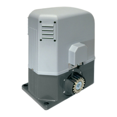
ThenameREVidentifiesaseriesofelectromechanicaloperatorsforslidinggateswithdifferentfeaturesastomotorandcontrol
boardpowersupplyvoltage,capacity,mechanicaladjustmentofforce,electronicclutchandbuilt-inlimitswitch.Allautomatedmo-
delsinvolvetheuseofadvancedcontrolunits(NETseries)equippedwithanti-crushingsensor,built-in433MHzradioreceiver,speed
controlandslowdowninopeningandclosing.TheREVmodelsareintendedprimarilyforresidential/condominiumandSemi-
intensive/intensiveusedependingonthedutycycleforeseenfortheautomation.
REViscompletedbyasetofaccessorieslistedinthe“PRODUCTACCESSORIES”table(page114).
REViscomposedofamechanicalgearmotorwhichrotatesthedrivinggear;Thisgear,coupledtotherackproperlyinstalledonthe
gate,convertsthecircularmotionofthegearmotorintorectilinearmotionthusallowingthemovementofthegateonitsownguide.
Inspectthe“ContentsofthePackage”(Pic.1)andcompareitwithyourproductforusefulconsultationduringassembly.
Transport
REVisalwaysdeliveredpackedinboxesthatprovideadequateprotectiontotheproduct,however,payattentiontoallinforma-
tionthatmaybeprovidedonthesameboxforstorageandhandling.
3 TECHNICAL DATA
REV220 - REV220/M -
REV220/IB
REV220/RF - REV220/RFM -
REV220/RF/IB
REV24/F - REV24/M -
REV24/IB
Motor power supply voltage (V) 230V~±10%(50/60Hz) 24V
Absorbed power (W) 500 250
Max Thrust (N) 900 1200 450
Work cycle
(leaf L=8m)
up to 1000 Kg 27cycles/hour 36cycles/hour
up to 1400 Kg 22cycles/hour 31cycles/hour
Maximum n° of opera-
tions in 24 hour
(leaf L=8m)
up to 1000 Kg 270 300 300
up to 1400 Kg 220 250 250
Built-in capacitor (µF) 18 -
Operating temperature range (°C) -20÷50°C
Motor thermal protection (°C) 150°C -
Opening speed (m/min) 10 12
Weight of product with package (Kg) 18
Protection degree IPX4
OPERATOR
CONTROL BOARD
NET24N
Power supply (V) 230V~±10%(50/60Hz)
Rated power transformer (VA) 250VA(230/22V)
Fuse F2 (A) (transformer) 2A
Batteries 2x12V1,3A
Fuse F1 (A) (batteries input) 15A
24V operators outputs 1x10A
Warning:Theabovevaluesarecalculatedbytakingthemaximumpower
suppliedbytherespectiveprocessors.Inabsoluteterms,themaximumcurrent
fromeachoutputmustnotexceed10A.
Auxiliaries power supply output +24V max200mA
“Warning” output +24V max15W
Electric lock output 24V max5Wormax1
art.110
Flashing light output 24V max15W
Operating temperature range (°C) -20÷50°C
Receiver frequency 433,92MHz
Transmitters type of coding HCSfix-code-HCSrollingcode
-Dip-switch
Max remote controllers managed 100
NET230N
Power supply (V) 230V~±10%(50/60Hz)
Fuse F2 (A) 5A
Fuse F1 (A) 160mA
230V operators outputs 2x600W
Auxiliaries power supply output 24V~max200mA
“Warning” output 230V~max150W
Electric lock output max1art.110or24V
outputmax5Wconfigurable
230V Flashing light output 230V~max40W
24V Flashing light output
24V max100mA(forled
flashinglight)art.LED24AIor
opengatewarninglight/courtesy
light
Operating temperature range (°C) -20÷50°C
Receiver frequency 433,92MHz
Transmitters type of coding HCSfix-code-HCSrollingcode
-Dip-switch
Max remote controllers managed 100

21
4 INSTALLATION AND ASSEMBLY
4.1 For a satisfactory installation of the product is important to:
• Ensurethatthefacilitycomplieswithcurrentregulationsandthendefinethefullprojectoftheautomaticopening;
• Ensurethatthroughoutthecourseofthegate,whileopeningandclosing,therearenofrictionpoints;
• Ensurethatthereisnodangerofderailmentandthattherearenotrisksthatitgoesoutoftheguides;
• Makesurethegateisinequilibrium:itmustnotmoveifitstaysinanyposition;
• Ensurethatthemountingareaofthemotorallowsthereleaseandamanualoperationeasierandsafer;
• Ensurethatthemountingpositionsofthevariousdevicesareprotectedfromimpactsandthesurfacesaresufficientlyrobust;
• Donotallowtheautomationpartsareimmersedinwaterorotherliquids.
4.2 Defined and satisfied these prerequisites, proceed to the assembly:
If the supporting plane is already available, the fixing of the motor must be done directly on the surface using, for example
screw anchors or chemical means.
Alternatively, proceed as follows:
• MakeaholeappropriatetothetypeoflandbyusingasareferencethemeasurementsshowninFig3;
• Provideanadequatenumberofchannelsforthepassageofelectricalcables;
• Placethebaseofthefoundation;
• Startcastingofconcreteand,beforeyoustarttaking,bringingthebaseplatetothedimensionsshowninFigure4,makingsure
thatisparalleltothegatewingandperfectlylevel.Waitforthecompletesettingoftheconcrete;
• Removethenutsfromtheplate,thenputthemotoronthebasisoffoundation.
If the rack is already present, place the pinion at a distance of 1-2 mm in order to avoid that the weight of the wing could
burden on the gear motor. To do this, adjust the height of the REV with the grains (Fig. 5) and then tighten the nuts in a robust
way.
Alternatively, proceed as follows:
• Unlockthemotorandfullyopenthedoor;
• Placethefirstsectionoftherackonthewing,makingsurethatthestartoftherackcorrespondstothetopofthewing.Then
attachtheracktotheleafkeepingagameof1-2mmfromthepinion(Fig.6);
• Cutofftheexcesspartoftherack;
• Finally,movethedoormanuallyseveraltimesandverifythatthealignmentandthedistanceof1-2mmbetweentherackand
pinionisrespectedthroughoutthelength;
• TightenthelocknutsofREVinarobustway(Fig.7)andcoverwithplasticcaps.
4.3 How to unlock the operator
Onceyouopenthelockonthehandle(protectedbyaplasticcover),thelevermustbeturnedinthedirectionshowninFig8,at
thispointtheoperatorisunlockedandthegate,intheabsenceofotherobstaclesisfreeinhismovements.Thereverseprocess,turn
theleveruntilitstopsandclosingofthelock(remembertoprotectthelockwiththepropercover),keepsREVinworkingcondition.
4.4 Limit-switches
Adjustment of the limit-switches
SomeREVmodelsprovidesalimit-switchwhoseinterventionmustbeadjustedforeachinstallation.DEASystemprovidestwolimit
switchescams(Fig.9)thatareinstalledontherackofthegateandsubsequentlyregulatedinsuchawayastoensurethefunctio-
nalityandsafetydistancesinopeningandclosingofthegate.
Keepinmindthatwhenthelimitswitchestrigger,thedoorwillmovetoanother2-3cm,andit’sthereforesuggestedtofixtheend
ofstrokebracketsatasufficientdistancefromthemechanicalstops.
Adjustment of the magnetic limit switch
AttachthemountingbracketstothemagnetsasshowninFigure11,making sure to mount the LIGHT BLUE magnet at the closing limit
switch, the GREEN magnet at the end of the opening limit switch(Fig.12).Connect the cable of the magnetic sensor which is colored
BROWN at the FCC 1 input (Closing Limit Switch 1) and the BLACK one at FCA 1 input (Opening Limit Switch 1)(Fig.13);
WARNINGRefertocontrolboardinstructionstocorrectlyidentifythelimitswitchinputs.
WARNINGIncorrectinstallationofthemagnetscanbedangeroustopeopleorthings;observetheconditionsprescribedinthesein-
structions.
MountthemagneticsensorasshowninFig.10.Thesensormustprotrudefromthebracketforsupportingatleast30mm,inthiswaywill
avoidanyinterference.
Adjustthemagnetssupportbracketssoastomaintainadistancefromthesensorbetween10and20mm;
4.5 Non self locking models
Nonselflockingmodelsallowthegatetomovemanually,withouthavingtouseareleasekeywhenthepowerfails.Nonself
lockingversionsareequippedwithaholdingbrakewhenopening/closing,Thismeansthegatewillbeselflockinginnormalope-
ration.
Refertotheattachedsheetforthecorrectprocedureofcleaning/maintenanceoftheelectro-brake.DEASystemremindsthat
theoperationsmustbeperformedbyqualifiedpersonnel.

22
5.1 ELECTRICAL CONNECTIONS FOR 24V MODELS
Execute the wiring following the directions of “Table 1” and diagrams on page 23.
WARNINGToensureanappropriatelevelofelectricalsafetyalwayskeepthe230Vpowersupplycablesapart(minimum4mm
intheopenor1mmthroughinsulation)fromlowvoltagecables(motorspowersupply,controls,electriclocks,aerialandauxiliary
circuitspowersupply),andfastenthelatterwithappropriateclampsneartheterminalboards.
WARNINGConnecttothepowersupply230V~±10%50Hzthroughamultipoleswitchoradifferentdevicethatcanensure
multipoledisconnectionfromthepowersupply,withacontactopeningof3mm.
WARNING Toconnecttheencodertothecontrolpanel,useonlyadedicatedcable3x0,22mm2.
Table 1 “terminal board connections”
1-2 +24V powersupplyoutputforauxiliarydevices200mA
3-4 22V~transformerpowersupplyinput
5-6 24V batterypowersupplyorphotovoltaicaccumulatorGreenEnergyinput(followcarefullypolarity
indications).
7-8 Operator1output
9Connectionofmotorsmetallicparts
10-11 Operator2output(ifpresent)
12-13 24V max15Woutputforopengatefix/flashingwarninglight(ifP052=0/1)orcourtesylight(ifP052>1)
14-15
14 (-) “Boost”outputforelectric-lock,max1xart.110(ifP062=0),24Vpulseoutput,max5W(ifP062=1),
step by step (if P062=2), electro-brake output for not self-locking operators (if P062=3), output for
electric-lockpowersupplyviaexternalrelay(ifP062=4),outputforelectro-magnetspowersupplyfor
barriers(ifP062=5)ortemporizedoutput(ifP062>5).
15 (+)
16-17 24V Flashinglightoutputmax15Wart.Lumy/24A/S
18-19 18 - N.C. Input6FCC1.IfitintervenesitstopsM1closing.If unused, short circuit.
Iftheinstallationrequiresdifferentcomman-
dsand/oradditionaltothestandard,you
can configure each input to the required
rate.
Refer to Chapter
“Advanced Programming”.
19 - Com
20-21 20 - N.C. Input5FCA1.IfitintervenesitstopsM1opening.If unused, short circuit.
21 - Com
22-23
22 - N.C. Input4PHOTO1.Whenenabled(seeparameterP050 in the table), activation of
PHOTO1provokes:aninversionofdirection(duringclosing),thearrestofthemo-
vement(duringopening),preventthestart(gateclosed).If unused, short circuit.
23 - Com
24-25 24 - N.C. Input3SAFETY.Ifactivated,itcausestheinversion.SeeP055andP056onthepara-
meterstable.If unused, short circuit.
25 - Com
26-27 26 - N.O. Input2PED.Ifactivated,itopensmotornr.1only.
27 - Com
28-29 28 - N.O. Input1START.Incaseofinterventionitprovokes:theoperatoropeningorclosing.It
mayoperateas“inversion”mode(P049=0)or“stepbystep”mode(P049=1).
29 - Com
30 Aerialsignalinput
31 Groundaerialinput
32-33 32 (+) DE@NETmainsinput(unusedatthemoment)
33 (-)
CON 1 230V~±10%(50/60Hz)powersupplyinput
J5 J9 EncoderselectionJumper:
•Aposition=operatorswithencoder(remindtosetP029=0)
•Bposition=operatorswithoutencoder(remindtosetP029=1)
AB AB

23
WIRING DIAGRAM FOR 24V
7 98 10 11 12 13 14 15 16 17
18
19
20
21
22
23
24
25
26
27
28
29
31 3033 32
2
1
4
3
6
5
ABAB
FLASHWARNING
J5 J9
F2
INTERNAL WIRING SET BY THE FACTORY
EXTERNAL WIRING SET BY THE INSTALLER
N.O.
N.O.
PED
N.C.
FCA1
N.C.
RG58
N.C.
START
FCC1
TX RX
PHOTO 1
OPEN GATE WARNING LIGHT
24V 15w
FLASH
LUMY/24A/S
max 15W
COM
N.O.
COM
N.O.
COM
N.C.
COM
N.C.
COM
N.C.
COM
N.C.
2 x 1 mm2
2 x 0,5 mm2
2 x 0,5 mm2
2 x 0,5 mm2
2 x 0,5 mm2
2 x 0,5 mm2
2 x 0,5 mm2
2 x 0,5 mm2
2 x 0,5 mm2
COM
N.C.
N.O.
CON1
230V 22V
FN
TRANSFORMER
230V/22V
POWER SUPPLY
230V~ 50Hz ±10%
F1
SAFETY (Only if needed)
RED
BLUE
Brown
Blue
Black
Blue

24
5.2 ELECTRICAL CONNECTIONS FOR 230V MODELS
Execute the wiring following the directions of “Table 2” and diagrams on page 25.
WARNINGToensureanappropriatelevelofelectricalsafetyalwayskeepthe230Vpowersupplycablesapart(minimum4mm
intheopenor1mmthroughinsulation)fromlowvoltagecables(motorspowersupply,controls,electriclocks,aerialandauxiliary
circuitspowersupply),andfastenthelatterwithappropriateclampsneartheterminalboards.
WARNINGConnecttothepowersupply230V~±10%50Hzthroughamultipoleswitchoradifferentdevicethatcanensure
multipoledisconnectionfromthepowersupply,withacontactopeningof3mm.
WARNING Toconnecttheencodertothecontrolpanel,useonlyadedicatedcable3x0,22mm2.
Tabella 2 “collegamento alle morsettiere”
1-2 230V~±10%(50/60Hz)powersupplyinput
3-4-5 Operator1output230V~max600W
6-7-8 Operator2output230V~max600W(ifpresent)
9-10 230V~max150Woutputforopengatewarninglight(ifP052=0)orcourtesylight(ifP052>1)
11-12 Flashinglightoutput230V~max40W
13-14
13 (-) “Boost”outputforelectric-lock,max1xart.110(ifP062=0),24Vpulseoutput,max5W(ifP062=1),
step by step (if P062=2), electro-brake output for not self-locking operators (if P062=3), output for
electric-lockpowersupplyviaexternalrelay(ifP062=4),outputforelectro-magnetspowersupplyfor
barriers(ifP062=5)ortemporizedoutput(ifP062>5).
14 (+)
15-16
Output24V max100mA;byselectingtheFL/WLjumper,youcanchoosethe230Flashoutputasa
24Voutput(ifthejumperissettoFL)orasaWarninglightoutput(ifjumpersettoWL).
Warning:theoutputcapacityallowstouseLEDflashinglightsonly
17-18 17 - N.C. Input6FCC1.IfitintervenesitstopsM1closing.If unused, short circuit.
Iftheinstallationrequiresdifferentcomman-
dsand/oradditionaltothestandard,you
can configure each input to the required
rate.
Refer to Chapter
“Advanced Programming”.
18 - Com
19-20 19 - N.C. Input5FCA1.IfitintervenesitstopsM1opening.If unused, short circuit.
20 - Com
21-22
21 - N.C. Input4PHOTO1.Whenenabled(seeparameterP050 in the table), activation of
PHOTO1provokes:aninversionofdirection(duringclosing),thearrestofthemo-
vement(duringopening),preventthestart(gateclosed).If unused, short circuit.
22 - Com
23-24 23 - N.C. Input3SAFETY.Ifactivated,itcausestheinversion.SeeP055andP056onthepara-
meterstable.If unused, short circuit.
24 - Com
25-26 25 - N.O. Input2PED.Ifactivated,itopensmotornr.1only.
26 - Com
27-28 27 - N.O. Input1START.Incaseofinterventionitprovokes:theoperatoropeningorclosing.It
mayoperateas“inversion”mode(P049=0)or“stepbystep”mode(P049=1).
28 - Com
29 Aerialsignalinput
30 Groundaerialinput
31-32 24V~powersupplyoutputforauxiliarydevices200mA
33-34 33 (+) DE@NETmainsinput(unusedatthemoment)
34 (-)

25
WIRING DIAGRAM FOR 230V
2
1
9 10 11 12 13 14 15 16
17
18
19
20
21
22
23
24
25
26
27
28
30 2932 31
3 4 5 6 7 8
WARNING LOCK
F2F1
FLASH
230V
MOT 1 MOT 2
34 33
WL/FL24V
FL / WL
INTERNAL WIRING SET BY THE FACTORY
EXTERNAL WIRING SET BY THE INSTALLER
N.O.
N.O.
PED
N.C.
FCA1
N.C.
RG58
N.C.
START
FCC1
TX RX
PHOTO 1
OPEN GATE WARNING LIGHT
230V max 150W
2 x 1 mm2
2 x 0,5 mm2
2 x 0,5 mm2
2 x 0,5 mm2
2 x 0,5 mm2
2 x 0,5 mm2
2 x 0,5 mm2
2 x 0,5 mm2
2 x 0,5 mm2
ENC
M1
F
N
BROWN
BLACK
GRAY
OMNIPOLAR CIRCUIT BRAKER
POWER SUPPLY
230V~ 50Hz ±10%
L
N
LUMY/A
max 40W
FLASH
230V
3 x 0,22 mm2
4 x 1,5 mm2
3 x 1,5 mm2
COM
N.C.
N.O.
SAFETY (Only if needed)
Brown
Blue
Black
Blue
COM
N.O.
COM
N.O.
COM
N.C.
COM
N.C.
COM
N.C.
COM
N.C.

26
6 STANDARD PROGRAMMING
1Power Supply
Givepowersupply,thedisplayshowsthefollowingsymbols“ ”,“ ”,“ ”andthen“----”.
*Ifthecontrolpanelhasalreadybeenprogrammedandthepowerfailsorisswitchedoff-oncepowerisreturnedandaSTART
commandisgiven,thepositionresetprocedureisperformed(see“rESP”inthetable“WORKINGSTATUSMESSAGES”onpage31.
2Visualisation of inputs and operations-counter status
1. Pressthe keyfor15seconds;
2. Thedisplaywillshowrespectively:
Inputsstatus(checkit’scorrect);
Totaloperationscounter(*seeP064):
i.g.: =3x100*=3000operationsperformed
Maintenanceoperations-counter(*seeP065):
i.g.: =5*x500=2500operationsremaining
beforethemaintenanceinterventionrequest( =
manoeuvres-counterdisabled)
3. Holddownthe keytodisplayacyclic3options,or
releasethe buttontoexittheparameter.
3Selection type of operators ! IMPORTANT !
1. Scrolldowntheparameterswith and keysuntilyouvi-
sualiseP028;
2. Accesstheparameterbypressingthe key;
3. Verifythatthevaluecorrespondstod007(REV),otherwise,you
mustselectitbypressing and keys;
4. Confirmyour choice bypressingthe key (displayreturns
againtoP028).

27
4Selection of direction of motion
1. Scrolldowntheparameterswith and keys
untilyouvisualiseP063;
2. Accesstheparameterbypressingthe key;
3. Actingon and keys,set:
-d000=motorinstandardposition(ontheleftof
thegap);
-d001=motorininvertedposition(ontherightof
thegap);
4. Confirmyourchoicebypressingthe key(di-
splayreturnsagaintoP063).
Warning: The parameter automatically reverses
the motors output open/close and any limit switch
input open/close.
5How to adjust the limit switche
1. Scroll down the parameters untill you visualize
P001;
2. confirmbypressingthe key;
3. bypressing (open)and (close),movethe
leafintheopeningpositionandadjustthelimit
switch cam so that it pushes the microswitch in
thatpoint;
Repeatadjustingtheclosinglimitswitch.
4. Confirm by pressing the key (display shows
againP001).
6 Motor stroke learning
1. Makesureyouhaveproperlyadjustedtheopening/closinglimitswitchescams;
2. Scrolldowntheparameterswith and keysuntilyouvisualiseP003;
3. Accesstheparameterbypressingthe key;
4. When“ ”flashes,continuepressingthe key;
5. Releasethe keywhen“ ”stopsflashing;Startthelearningprocedurewithoperator1opening;
6. Waitforthedoorsearchesandstopsontheopeningstopandthenontheclosingstop.
7. Oncetheprocedureisended,thedisplaywillshow“----“.
7Transmitters learning
7.1 Transmitters coding selection
1. Scrolldowntheparameterswith and keysuntilyouvisualise
P027;
2. Confirmbypressingonthe key;
3. Selectthetypeoftransmitterbyscrolling and keys:
-d000=fixrolling-code(suggested);
-d001=completerolling-code;
-d002=dip-switch;
4. Confirmbypressingonthe key(displayshowsagainP027).
Warning: If you need to vary the type of encoding, and only if other
remotes with different encoding are memorized, you need to erase
memory (P004) AFTER you have set the new encoding.

28
9.2 Learning
1. Scrolldowntheparameterswith and
keysuntilyouvisualiseP005;
2. Confirmbypressingonthe key;
3. When the symbol “ ” appears, press
on any key of the transmitter you want to
memorize;
4. The display visualizes the number of the
transmitterjustmemorizedandthen“ ”;
5. Memorizeallnecessarytransmittersrepeat-
ingthisprocedurefromstep3;
6. Wait10secondsbeforequittingthememo-
rizationmode,displayshowsnow“----“.
Warning: In the case of rolling code remotes,
the receiver can be put into learning mode
by pressing the hidden button on a remote
control previously learned.
8Adjustment of operating parameters
Ifyouneedtomodifytheoperatingparameters(force,speedness
etc..):
1. Scrolldowntheparametersuntilyouvisualizethedesirepa-
rameter(i.g.P032);
2. Confirmbypressingonthe key;
3. Bypressingon and ,setupthedesiredvalue;
4. Confirmbypressingonthe key(displayshowstheparam-
eterspreviouslyselected).
For the complete list of the “Operating Parameters” See
the table on page. 34.
9Programming complete
WARNINGAttheendoftheprogrammingprocedure,usethebuttons and untiltheappearanceofthesymbol“----”,the
operatorisnowreadyagainfornewmanoeuvres.
To perform any “Advanced Programming” operations (cancellation of the remotes, configuration inputs, etc. ..),
see on page 29.

29
7 ADVANCED PROGRAMMING
Herearesomeaddedprogrammingproceduresrelatingtoremotesmemorymanagementandadvancedconfigurationofthe
controlinputs.
1Deletion of memorized transmitters
1.1 Deletion of all transmitters
1. ScrolldowntheparametersuntilyouvisualizeP004;
2. Confirmbypressingonthe key;
3. When “ ” is flashing, press the key for a few
seconds;
4. Releasethe keyassoonas“ ”stopsflashing;
5. Allmemorizedtransmittershave beendeleted(display
showsagainP004).
1.2 How to search and delete a transmitter
1. ScrolldowntheparametersuntilyouvisualizeP006;
2. Confirmbypressingonthe key;
3. Bypressingon and ,keys,selectthetransmitter
youwanttodelete(eg. );
4. When“ ”flashes,confirmthedeletionbypressing
the keyforafewseconds;
5. Releasethe keywhenappears“ ”;
6. Theselectedtransmitterisdeleted(displayshowsagain
P006).
2Resetting of default parameters
1. ScrolldowntheparametersuntilyouvisualizeP007;
2. Confirmbypressingonthe key;
3. When“ ”flashes,pressthe key;
4. Releasethe keyassoonas“ ”stopsflashing;
Defaultparametersfortheconfigurationcurrentlyin
usearerestored;
5. AttheendoftheoperationdisplayreturnstoP007.
Warning: Afteryourestorethedefaultparameters,you
must program the control panel again and adjust all
operatingparameters,inparticular,remembertopro-
perlysettheconfigurationofparameters(P028-P029
-P030–operatorconfiguration).
3Locking-Unlocking access to programming
Byusinga“dip-switch”remote(regardlessofthetypeofremotesalreadymemorized)it’spossibletolock-unlockaccesstothepro-
grammingofthecontrolpaneltoavoidtampering.Theremotesettingisthelocking-unlockingcodeverifiedbythecontrolboard.
3.1 Locking access to programming
1. Scrollthroughtheparameterswiththebuttons
and untilthedisplayshowsP008;
2. Accesstheparameterbypressingthebutton ;
3. The display shows alternately the writing
toindicatethatthecontrolboard
iswaitingforthetransmissionoftheblockcode;
4. Within10secondspressCH1onthe“TXMas-
ter”, the display shows before
returningtothelistofparameters;
5. Accesstoprogrammingislocked.

30
3.2 Unlocking access to programming
1. Scrollthroughtheparameterswiththebuttons
and untilthedisplayshowsP008;
2. Accesstheparameterbypressingthebutton ;
3. The display shows alternately the writing
toindicatethatthecontrolboard
iswaitingforthetransmissionoftheunlocking
code;
4. Within10sec.presstheCH1ofthe“TXMas-
ter”, the display shows before
returningtothelistofparameters;
5. Accesstoprogrammingisunlocked.
3.3 Unlocking access to programming and global reset
WARNING! This procedure involves the loss of all
stored settings.
Theprocedureallowstheunlockingofthecontrolpanelwithout
havingtoknowitsunlockingcode.
Following this release, you must program the control panel
againandadjustalloperatingparameters,in particular, re-
member to properly set the configuration of parame-
ters (P028 - P029 - P030 – operator configuration). You
will also need to repeat the measurement of impact forces to
ensure the installation compliance to standards.
1. Scrollthroughthe parameters with the buttons and
untilthedisplayshowsP008;
2. Accesstheparameterbypressingthebutton ;
3. Thedisplayshowsalternatelythewriting ;
4. Press the button , the display shows the flashing writing
;
5. Pressthebuttonagainandholdfor5seconds(releasingit
before,theprocedureisterminated):Thedisplayshowsthe
fixedwriting followedby ,beforereturningtothe
listofparameters;
6. Accesstoprogrammingisunlocked.
4Inputs configuration
Wheretheinstallationrequiresdifferentcommandsand/oradditionalto
thestandardonesdescribedbyplan,youcanconfigureeachinputforthe
operationdesired(egSTART,PHOTOS,STOP,etc...).
1. Scrolldowntheparameterswiththe and toseethatcorrespond-
ingtothedesiredone:
●P017=forINPUT1;
●P018=forINPUT2;
●P019=forINPUT3;
●P020=forINPUT4;
●P021=forINPUT5;
●P022=forINPUT6;
2. Confirmbypressingonthe keytogetaccesstotheparameter(eg.
P018);
3. Scrolldownwiththe and ,keystosetthevaluecorrespondingto
thedesiredoperation(refertotable“InputConfigurationparameters”
on page 33);
4. Confirmbypressingonthe key(displayshowsagainP018).
5. Executethenewconnectiontotheinputjustreconfigured.
5Programming complete
WARNINGAttheendoftheprogrammingprocedure,usethebuttons and untiltheappearanceofthesymbol“----”,the
operatorisnowreadyagainfornewmanoeuvres.

31
8 MESSAGES SHOWN ON THE DISPLAY
WORKING STATUS MESSAGES
Mess. Description
Gateisclosed
Gateisopened
Openingunderway
Closingunderway
Whileinstep-by-stepmode,thecontrolboardawaitsfurtherinstructionsafterastartcommand
Stopcommandreceived
Resetcurrentposition:Thecontrolunithasjustbeenturnedonafterapowerfailure,orthegatehasexceededthemaximumnumber(80)
ofinversionsallowedwithoutevergettingtotheclosingstroke,orthemaximumnumber(3)ofconsecutiveoperationsallowedoftheanti-
crushingdevice.
Oncethecontrolunithasbeenresetandopencommandgiventhegatewillstartmovingatslowspeed,untilitreachesendoftravel.
ERROR MESSAGES
Mess. Description Possible solutions
Errorposition:Theresetpositionprocedureisnotsuc-
cessful.Thecontrolpanelisawaitingcommands.
-Makesuretherearenospecificfrictionsand/orobstaclesduringtherun;
-Giveastartpulsetoinitiateapositionresetprocedure;
-Verifythattheoperationiscompletedsuccessfully,manuallyhelpingtherun,if
necessary;
-Adjustpowerandspeedsettingsifnecessary.
Externalphotocellsand/orsafetydevicesareactivat-
edoroutoforder. -Makesurethatallsafetydevicesand/orphotocellsinstalledareworkingproperly.
Possiblefailuretothecontrolboardpowercircuit. -Disconnectandconnectpowersupply.Giveastartimpulse,ifthiserrorappears
again,replacethecontrolboard.
Time-outoperatorsrun: The engine/sexceeded the
maximum operating time (5min) without ever stop-
ping.
-Giveastartpulsetostartthepositionresetprocedure;
-Ensurethatthisoperationissuccessful.
Time-outobstacledetection:Withanti-crushingsen-
sordisabled,wasstilldetectedthepresenceofanob-
staclethatpreventsmovementoftheleafforaperiod
of10secondsmore.
-Makesuretherearenospecificfrictionsand/orobstaclesduringtherun;
-Giveastartpulsetoinitiateapositionresetprocedure;
-Verifythattheoperationiscompletedsuccessfully.
Operatorsmouvementnotdetected.
-Makesurethatoperatorsandencodersconnectionsarewelldone.
-CheckthatjumpersJ5andJ9arewellpositionedasshownontheelectricwiring
(for24Vonly).
-Ifthiserrorappearsagain,replacethecontrolpanel.
9 START-UP
Thestart-upphaseisveryimportanttoensuremaximumsecurityandcompliancetoregulations,includingalltherequirementsof
EN12445standardwhichestablishesthetestmethodsfortestingtheautomationforgates.
DEASystemremindsthatallinstallation,maintenance,cleaningorrepairoperationsonanypartofthesystemmustbeperformed
exclusivelybyqualifiedpersonnelwhomustberesponsibleofalltextsrequiebytheeventualrisk;
9.1 Installation test
Thetestingoperationisessentialinordertoverifythecorrectinstallationofthesystem.DEASystemwantstosummarizethe
propertestingofalltheautomationin4easysteps:
• Makesurethatyoucomplystrictlyasdescribedinparagraph2“WARNINGSSUMMARY”;
• Testtheopeningandclosingmakingsurethatthemovementoftheleafmatchasexpected.Wesuggestinthisregardtoperform
variousteststoassessthesmoothnessofthegateanddefectsinassemblyoradjustment;
• Ensurethatallsafetydevicesconnectedworkproperly;
• Performthemeasurementofimpactforcesinaccordancewiththestandard12445tofindthesettingthatensurescompliance
withthelimitssetbythestandardEN12453.
WARNING UsingsparepartsnotindicatedbyDEASystemand/orincorrectre-assemblycancreatearisktopeople,animals
andpropertyandalsodamagetheproduct.Forthisreason,alwaysuseonlythepartsindicatedbyDEASystemandscrupulously
followallassemblyinstructions.
9.2 Unlocking and Manual operation
Intheeventofmalfunctionsorsimplepowerfailure,releasethemotor(Pic.8)andperformtheoperationmanually.
Theknowledgeoftheunlockingoperationisveryimportant,becauseintimesofemergencythelackoftimelinessinactingon
suchadevicecanbedangerous.
WARNINGTheefficancyandsafetyofmanualoperationoftheautomationisguaranteedbyDEASystemonlyiftheinstallation
hasbeeninstalledcorrectlyandwithoriginalaccessories.

32
10 MAINTENANCE
Goodpreventivemaintenanceandregularinspectionensure
longworkinglife.Inthetablebelowyouwillfindalistofinspec-
tions/maintenanceoperations tobeprogrammedandexecuted
periodically.
ConsulttheTROUBLE-SHOOTING”tablewheneveranoma-
liesareobservedinordertofindthesolutiontotheproblemand
contactDEASystemdirectlywheneverthesolutionrequiredisnot
provided.
INTERVENTION TYPE PERIODICITY
cleaning of external surfaces 6 months
checking of screw tightening 6 months
checking of release mechanism operation 6 months
electric brake cleaning 6 months
TROUBLE-SHOOTING
Description Possible solutions
When the opening or closing command is activated the
gate leaf fails to move and the operator’s electric mo-
tor fails to start.
Theoperatorisnotreceivingcorrectpowersupply.Checkallconnections,fuses,andthe
powersupplycableconditionsandreplaceorrepairifnecessary.Ifthegatedoesnotclose
checkthecorrectfunctioningofphotocells.
When the opening command is activated, the motor
starts but the gate leafs fail to move.
Checkthattheunlockingsystemisclosed(seePic.8).
Checktheelectronicforceadjustmentdeviceandthemechanicalclutch.
Makesurethatthemotordoesnotpushintheoppositedirection,thelimitswitchelectri-
calconnectionsmightbereversed.
The gate moves by fits and starts, it is noisy, it stops at
half run or it does not start.
Makesurethatnothinghindersthegatewheelsmovementandtheslideinwhichtheyroll.
Therealwaysmustbebacklashbetweenrackandpinion;makesuretherackisaccura-
telypositioned.
Thepowerofthegearmotormaybeinsufficientforthecharacteristicsofthegate’swing;
checkthechoiceofmodelwheneverrequiredh.
Iftheoperatorattachmenttothegatebendsorisbadlyfastened,repairand/orbuttress
it.
11 PRODUCT DISPOSAL
REVconsistsofmaterialsofvarioustypes,someofwhichcanberecycled(electricalcables,plastic,aluminum,etc...)whileothers
mustbedisposedof(electronicboardsandcomponents).
Proceedasfollows:
1. Disconnectthepowersupply;
2. Disconnectanddisassemblealltheaccessoriesconnected.Followtheinstructionsinreversetothatdescribedinthesection“Instal-
lation”;
3. Removetheelectroniccomponents;
4. Sortinganddisposingofthematerialsexactlyaspertheregulationsinthecountryofsale.
WARNINGInlinewithEUDirective2002/96/ECforwasteelectricalandelectronicequipment(WEEE),thiselectricalproduct
mustnotbedisposedofasunsortedmunicipalwaste.Pleasedisposeofthisproductbyreturningittoyourlocalmunicipalcol-
lectionpointforrecycling.

33
PAR. PROCEDURE SETTABLE VALUES
PROGRAMMING PROCEDURES
Positioningofoperator1
Positioningofoperator2
Memorizationofthemotors’stroke
Deletionoftransmitters
Transmittersmemorizing
Searchanddeletionofatransmitter
Loadingofstandardparameters:thelistisupdatedwithfactorysettings
Lockaccesstoprogramming
HowtolearnconnectedDE@NETdevices(unusedatthemoment)
Unusedparameter
Unusedparameter
Unusedparameter
Unusedparameter
Unusedparameter
Unusedparameter
PAR. PARAMETER DESCRIPTION SETTABLE VALUES
DEFAULT VALUES
(fordifferentstandardsofinstallation)
sliding gate 24V sliding gate 230V
INPUTS CONFIGURATION PARAMETERS
INPUT_3selectioninginputtype •000:IN3type=freecontact
•001:IN3type=constantresistance8K2 (freecontact) (freecontact)
INPUT_1operatingselection •000:NONE(unusedparameter)
•001:START(start)
•002:PED.(pedestrian)
•003:OPEN(separatedopen)
•004:CLOSE(separatedclose)
•005:OPEN_PM(manpresentopen)
•006:CLOSE_PM(manpresentclose)
•007:ELOCK-IN(electric-lockactivation.SeeP062)
•008:PHOTO1(photocell1)
•009:PHOTO2(photocell2)
•010:SAFETY1(safetyrib1)
•011:STOP(lock)
•012:FCA1(openinglimitswitchesMot1)
•013:FCA2(openinglimitswitchtesMot2)
•014:FCC1(closinglimitswitchesMot1)
•015:FCC2(closinglimitswitchesMot2)
•016:SAFETY2(safetyrib2)
IN1 (START) (START)
INPUT_2operatingselection IN2 (PEDESTRIAN) (PEDESTRIAN)
INPUT_3operatingselection IN3 (SAFETY) (SAFETY)
INPUT_4operatingselection IN4 (PHOTO1) (PHOTO1)
INPUT_5operatingselection IN5 (FCA1) (FCA1)
INPUT_6operatingselection IN6 (FCC1) (FCC1)
AllocationofCHANNEL1ofremotes •000:NONE(unusedparameter)
•001:START(start)
•002:PEDESTRIAN(pedestrian)
•003:OPEN(separatedopen)
•004:CLOSED(separatedclose)
•005:OPEN_PM(manpresentopen)
•006:CLOSED_PM(manpresentclose)
•007:ELOCK-IN(electric-lockactivation.SeeP062)
CH1 (START) (START)
AllocationofCHANNEL2ofremotes CH2 (NONE) (NONE)
AllocationofCHANNEL3ofremotes CH3 (NONE) (NONE)
AllocationofCHANNEL4ofremotes CH4 (NONE) (NONE)
Selectionoftypeofremotes •000:HCSfix-code
•001:HCSrolling-code
•002:Dip-switch

34
sliding gate 24V sliding gate 230V
OPERATORS
CONFIGURATION
PARAMETERS
Selectiontypeofoperators •005:LIVI5/24
•006:LIVI8/24
•007:GULLIVER/REV
Unusedparameter
Unusedparameter
OPERATING PARAMETERS
Operatorsspeedadjustmentduringslow-downwhileopening
Warning (230V only): For operators without
encoder,speedduringopening/closingcycles(100%)
and slow down speed during opening/closing cycles
(30%)arefixedindependentlyfromsetvalues.
15%tot........................100%tot
Operatorsspeedadjustmentduringthestrokewhileopening 15%tot........................100%tot
Operatorsspeedadjustmentduringthestrokewhileclosing 15%tot........................100%tot
Operatorsspeedadjustmentduringslow-downwhileclosing 15%tot........................100%tot
Slowdowndurationadjustmentwhileopening 5%tot............................80%to
Slowdowndurationadjustmentwhileclosing 5%tot............................80%tot
Operator1forceadjustmentwhileopening
(if=100%obstacledetectiondeactivated)
15%tot…...........................100%tot
Operatorn.1forceadjustmentwhileclosing
(if=100%obstacledetectiondeactivated)
15%tot…...........................100%tot
Unusedparameter
Unusedparameter
Automaticclosingtimesadjustment
(if=0automaticclosingdeactivated)
0sec...................................255sec
Pedestrianautomaticclosingtimeadjustment
(se=0pedestrianautomaticclosingdeactivated)
0sec...................................255sec
Pedestrianstrokedurationadjustment 5%tot…...........................100%tot
Pre-flashingtimeadjustment 0sec…….10sec
Unusedparameter
Unusedparameter
Collectivityfunction:ifitisactivateditdeactivatesbothopeningandclosinginputsforthewholedurationofautomaticopeningandclosing •000:“collectivityfunction”deactivated
•001:“collectivityfunction”activated
Ramblowfunction:itpushesthemotorsclosedforonesecondbeforeeachopeningmovement,soastoeasetheelectric-lockrelease •000:“ramblow”deactivated
•001:“ramblowfunction”activated
“Reversal”modeselection(duringthemanoeuvreacommandimpulsereversethemouvement)or“stepbystep”(duringthemanoeuvrea
commandimpulsestopsthemouvement).Anextimpulserestarttheoperatortotheoppositedirection.
•000:“reversalfunction”
•001:“stepbystepfunction”
PHOTO1 PHOTOinputfunctioning:If=0:photocellenabledwhileclosingandstartingwhenthegateisstopped;if=1photocellsare
alwaysenabled;if=2photocellsareenabledwhileclosingonly.Whenenabled,itsactivationprovokes:theinversion(while
closing),thestop(whileopening)andpreventthestarting(whengateisclosed).
If=3-4-5,theoperationisthesameasthevalues0-1-2butwith“closeimmediately”enabled:inanycase,duringtheopening
and/orthepausetime,removalofapossibleobstaclecausesthegateautomaticallyclosesafterafixeddelayof5sec.
•000:photocellenabledwhileclosingandwhengateisstopped
•001:photocellsalwaysenabled
•002:photocellsenabledonlywhileclosing
•003:as000butwith“closeimmediately”enabled
•004:as001butwith“closeimmediately”enabled
•005:as002butwith“closeimmediately”enabled
PHOTO2

35
sliding gate 24V sliding gate 230V
OPERATING PARAMETERS
Operationmodeselectionofthewarninglightoutput:
If=0“warninglight”(outputalwaysONwhenthegateisopen,OFFafteraclosingoperation),
If=1“flashingwarninglight”(slowintermittentoutputduringopeningandfastwhileclosing,alwaysONatgateopened,alwaysOFFatthe
endofaclosingoperationonly),
If>1“courtesylight”(outputONduringeachmovement,OFFwhenthemotorstops,afterthesettingdelay)
•000:“fixwarninglight”
•001:“flashingwarninglight”(only for 24V)
•>001:“courtesylight”offdelay
(1sec………………255sec)
Unusedparameter
“softstart”function:motorsaccelerategraduallyuntiltheyreachthesetspeed,avoidingsuddendepartures.
Warning (230V only):Foroperatorswithoutencoder,theparameterwillbeingnored.
•000:“softstart”deactivated
•001:“softstart”activated
•002:“longsoftstart”activated
Adjusttheinversiononobstacleperiod(detectedbyinternalanti-crushingsensororbythesafetyinputwhenactivated):If=0itmakesa
completeinversion,if>0indicatestheduration(inseconds)oftherun,afterinversionresultingfrom detection of an obstacleduringthe
opening.
•000:inversionecompletasuostacolo
•>000:duratadell’inversionesuostacolo
(1sec……………..10sec)
Adjusttheinversiononobstacleperiod(detectedbyinternalanti-crushingsensororbythesafetyinputwhenactivated):If=0itmakesa
completeinversion,if>0indicatestheduration(inseconds)oftherun,afterinversionresultingfromdetectionofanobstacleduringtheclosing.
•000:completereversalonobstacle
•>000:durationofreversalonobstacle
(1sec……………..10sec)
Facilitationmanualrelease:If≠0,afterdetectingthelockingstop,theenginereversesforabrieftimetoreleasethepressureonit,andthus
facilitatethemanualrelease.Thesetvalueshowsthelengthoftheinversion.If=0functiondisabled
•000:facilitatingreleasedisabled
•>000:facilitationactivatedwithreleasetimeequalto:
(1x25ms……….................40x25ms)
Unusedparameter
Unusedparameter
Unusedparameter
“Energysaving”mode:If=1after10secofinactivity,thecontrolpanelturnsthe24Voutputsandthedisplayoffthatwillbeturnedonatfirst
commandreceived(userecommendedbattery-poweredand/orsolarpanel).
•000:“Energysaving”notactive
•001:“Energysaving”active
Electric-lockoutputoperating:If=0“boost”outputforelectric-lockart.110powersupply,If=124VoutputcontrolledbytheELOCK_INinputas
pulsedmode,If=224VoutputcontrolledbytheELOCK_INinputasstep-by-stepmode,If=3electro-brakeoutputfornotself-lockingoperators,
If=424Voutputforelectric-lockpowersupplyviaanexternalrelay,If=524Voutputforelectro-magnetspowersupplyforbarriers,If>524V
outputcontrolledbytheELOCK_INinputastemporizedmode(thesetvalueindicatestheswitch-offdelayinseconds).
•000:“Boost”outputforelectric-lockart.110powersupply
•001:“24V pulseoutputmax5W
•002:“24V step-by-stepoutputmax5W
•003:“Electric-lockoutputfornotself-lockingoperators
•004:“Outputforelectric-lockpowersupplyviaanexternalrelay
•005:“outputforelectro-magnetspowersupplyforbarriers
•>005:“24V temporizedoutputmax5W
(5sec………………255sec)
Rundirectioninversion:If=1automaticallyreversestheoutputsopen/closeoftheoperatorsandanyopening/closinglimitswitchesinputs,
avoidinghavingtomanualchangethewiringwheninstallingtheoperatorinaninvertedposition.
•000:“Standardinstallation”
•001:“Invertedinstallation”
Multiplieroperations-counter:Multiplythenumberofoperationsafterwhichthetotaloperations-counterwillbeupdated.
Toviewthevalues,refertothesection“Visualisationofinputsandoperations-counterstatus”.
•000:“x100
•001:“x1000
•002:“x10000
•003:“x100000
MaintenanceOperations-counter:if=0resetthecounteranddisablestheinterventionrequest,if>0indicatesthenumberofoperations(x
500)tobemadebeforethecontrolpanelexecutesa4secondadditionalpre-flashtoindicatetheneedofmaintenance.
i.g.:IfP064=050,operationsnumber=50x500=25000operations
Warning:Beforeyousetanewvalueofthecounter-manoeuvresmaintenance,thesamemustberesetbysettingP065=0andonlylater
P065=“newvalue”.
•000:“RequestMaintenancedisabled
•>000:“Numberofoperations(x500)forrequiredmaintenance
(1...................................255)
Selectionofoperatingflashinglightoutput:If=0intermittentflashinglightoutput;
If=1Fixedflashinglightoutput(forflashinglightswithintermittentinteriorcircuits).
•000:“intermittentflashinglightoutput
•001:“fixedflashinglightoutput

36
sliding gate 24V sliding gate 230V
OPERATING PARAMETERS
SAFETY1 OperationoftheSFTinput:if=0safetyedgealwaysenabled,if=1safetyedgeenabledonlywhileclosing,if=2safetyedge
enabledonlywhileclosingandbeforeanymovement,if=3safetyedgeenabledonlywhenopening,if=4safetyedgeenabled
onlywhileopeningandbeforeanymovement;asfortheobstacledetectionwithinternalanti-crushingsensor,alsotheactivation
oftheinputsSFT1andSFT2causesthecompleteorpartialreversalassetbyP055(durationofinversiononobstacleswhile
opening,andP056(durationofreversalonobstaclewhileclosing)
•000:“safetyedgealwaysenabled
•001:“safetyedgeenabledonlywhileclosing
•002:“safetyedgeenabledonlywhileclosingandbeforeanymovement
•003:“safetyedgeenabledonlywhenopening
•004:“safetyedgeenabledonlywhileopeningandbeforeanymovement
SAFETY2
Delayonlimitswitchdetection:theoperationisstoppedafter1,5secfromlimitswitchdetection.Whenduringthisdelayastopisdetected,
theoperatorissuddenlystopped
•000:“limitswitchdelaydisabled
•001:“limitswitchdelayenabled
Adjustmentofaccelerationdurability
Warning:ifsoftstartisactivated,theaccelerationisdeactivatedindipendentlyfromP070value.
• 000: “acceleration deactivated (it runs an acceleration of minimum durability,
almostimperceptible)
•00X:“adjuststheaccelerationdurabilityat1,5sec(X*6ms)
Unusedparameter
Unusedparameter
Unusedparameter
Unusedparameter
Unusedparameter

Other manuals for REV Series
1
Table of contents
Other Dea Garage Door Opener manuals
Popular Garage Door Opener manuals by other brands

Topens
Topens MultiRuta CASAR 800 user manual

Nice
Nice THOR Instructions and warnings for the fitter

Superlift
Superlift SDO-3DC Installation instructions and user guide

Ribind
Ribind K800 manual

Overhead door
Overhead door RapidSlat 611 Operational & maintenance manual

Stagnoli
Stagnoli ACHILLES-1200 230V instructions