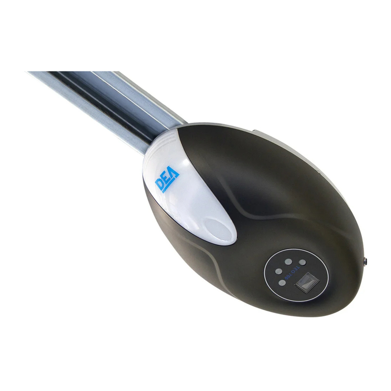
Dea TEO 700 Product manual

TEO 700
Operatore elettromeccanico per porte sezionali
Istruzioni d’uso ed avvertenze
Sectional door electromechanical operator
Operating instructions and warnings
Moto-reducteur pour portes sectionnelles
Notice d’emploi et avertissements
Elektromechanischer Antrieb für Sektionaltore
Bedienungsanleitung und Hinweise
Operador electromecánico para puertas seccionales
Instrucciones de uso y advertencias
Operador electromecânico para portas seccionais
Instruções para utilização e advertências
Urządzenie elektromechaniczne do bram segmentowych
Instrukcja montażu i użytkowania
Электро-механический привод для секционных ворот
Инструкции и предупреждения
I63602X Rev. 04 (25-09-18)

La Dichiarazione di Incorporazione può essere consultata sul sito
The Declaration of Incorporation may be consulted by entering
La Déclaration d’Incorporation peut être vérifié à l’adresse
Die Einbauerklärung kann abgerufen werden auf der Homepage
La Declaracion de Incorporación puede ser consultada en la dirección de internet
A Declaração de Incorporação pode ser consultada em
Deklarację Zgodności można skonsul tować wchodząc na st ronę
Декларация о регистрации можно ознакомиться, введя
http://www.deasystem.com
Nome ed indirizzo della persona autorizzata a costituire la
Documentazione Tecnica pertinente:
DEA SYSTEM S.p.A.
Via Della Tecnica, 6
36013 PIOVENE ROCCHETTE (VI) - ITALY
LIEVORE TIZIANO
Amministratore

9
TEO 700
Sectional door electromechanical operator
Operating instructions and warnings
Index
1Warnings Summary 97Start-up 14
2Product Description 10 7.1 Installation Test 14
3Technical data 10 7.2 Unlocking and manual operation 14
4Installation and Assembly 10 8Maintenance 14
5Electrical Connections 11 9Product Disposal 15
6Programming 12
Product Conformity
DEA System guarantees the conformity of the product to European Directives 2006/42/CE regarding “machinery safety”, 2014/30/
EU “electromagnetic compatibility” and 2014/35/EU “low voltage electrical equipment”. See Declaration of Incorporation.
1 WARNINGS SUMMARY
Read these warnings carefully; failure to respect the following warnings may cause risk situations.
WARNING Using this product under unusual conditions not foreseen by the manufacturer can create situations of danger, and for this
reason all the conditions prescribed in these instructions must be respected.
WARNING DEA System reminds all users that the selection, positioning and installation of all materials and devices which make up
the complete automation system, must comply with the European Directives 2006/42/CE (Machinery Directive), 2014/30/EU (electro-
magnetic compatibility), 2014/35/EU (low voltage electrical equipment). In order to ensure a suitable level of safety, besides complying
with local regulations, it is advisable to comply also with the above mentioned Directives in all extra European countries.
WARNING Under no circumstances must the product be used in explosive atmospheres or surroundings that may prove corrosive and
damage parts of the product.
WARNING To ensure an appropriate level of electrical safety always keep the 230V power supply cables apart (minimum 4mm in
the open or 1 mm through insulation) from low voltage cables (motors power supply, controls, electric locks, aerial and auxiliary circuits
power supply), and fasten the latter with appropriate clamps near the terminal boards.
WARNING All installation, maintenance, cleaning or repair operations on any part of the system must be performed exclusively by
qualied personnel with the power supply disconnected working in strict compliance with the electrical standards and regulations in
force in the nation of installation.
WARNING Using spare parts not indicated by DEA System and/or incorrect re-assembly can create risk to people, animals and
property and also damage the product. For this reason, always use only the parts indicated by DEA System and scrupulously follow all
assembly instructions.
WARNING Incorrect assessment of the impact forces can cause serious damage to people, animals or things. DEA System reminds
the installer must verify that the impact forces, measured as indicated by the standard EN 12445, are actually below the limits set by
the standard EN12453.
WARNING Any external security devices used for compliance with the limits of impact forces must be conform to standard EN12978.
WARNING In compliance with EU Directive 2012/19/EU on waste electrical and electronic equipment (WEEE), this electrical prod-
uct should not be treated as municipal mixed waste. Please dispose of the product and bring it to the collection for an appropriate
local municipal recycling.

10
2 PRODUCT DESCRIPTION
Models and contents of the package
Under the name TEO 700 is identied a family of 24V electromechanical operators with built-in control board for adjusting the forces
while opening/closing and for managing optional features such as photocells, automatic closing, etc. .. Functions OPEN - CLOSE - STOP
operated by a single key, change of direction when an obstacle is detected in closing, led courtesy light in opening and closing with auto-
off after 3 minutes, protective functions for inputs in low and high voltage, short circuit, etc. .
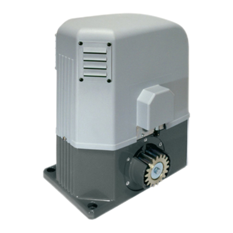
TEO 700 is an electromechanical operator for the automation of sectional, overhead counterweight and spring doors. It is basically
made up of a mechanical operator rotating the draft gear that, through a chain, transmits the movement directly to the door draft system
thus moving it.
Inspect the “Content of the package” (Pic. 1) and compare it with your product for useful consultation during assembly.
Transport
TEO 700 is always delivered packed in boxes that provide adequate protection to the product, however, pay attention to all informa-
tion that may be provided on the same box for storage and handling.
3 TECHNICAL DATA
TEO 700
CONTROL BOARD OPERATOR
Power supply (V) 230 V ~ ±10% (50/60 Hz) Motor power supply voltage (V) 24 V
Rated power transformer (VA) 100 VA (230/22V) Absorbed power (W) 100
Fuse F2 (A) (transformer) 2,5A 250V Max Thrust (N) 1000
Auxiliaries power supply output +24 V max 200mA Work cycle (cycles/hour) 15
Flashing light output 24 V max 15W Maximum n° of operations in 24 hour 35
Receiver frequency 433,92 MHz Operating temperature range (°C) -20÷50
Transmitters type of coding HCS rolling code Opening speed (m/min) 9
Max remote controllers managed 20 Weight of product with package (Kg) 4,3
Protection degree IP30
4 INSTALLATION AND ASSEMBLY
4.1 For a satisfactory installation of the product is important to:
• Ensure the door frame is solid and suitable to be driven;
• Make sure that during its movement it doesn’t present friction points;
• Check it is well balanced. If required adjust the balancing mechanisms;
• Foresee an adequately protected 230V socket near the automation.
4.2 Dened and satised these prerequisites, proceed to the assembly:
• Assemble the track (2) to the main unit (1) by inserting the motor pin inside the pinion (Picture 3);
• Fix the track to the main unit by using the two supports (3);
• Mount the angular support bracket (4) and x it with the xing support (we suggest to keep it as close as possible to the main unit);
Warning: bigger is the distance of the angular support from the main unit, smaller is the part of track available.
• Combine the angular support with the two ceiling xing brackets (5) (adjust the brackets so that the track, once xed, is perfectly horizontal);
• Fix the front bracket (6) to the track fork;
• Mount the release blade (8) on the release base (7) positioned on the track and x it with the 4 screws provided (Picture 4);
• Secure the track to the door frame (if possible) or to the wall with screws or bolts suitable to the material respecting a distance of at least
40mm. from the maximum door stroke;
• Lift the main unit and x it to the ceiling by using proper tools for the material/surface (Picture 5);
• Combine the straight lever (9) with the curved one (10) and x them to the release blade;
• Combine the connecting bracket (11) to the curved lever and then secure them on the top side of the door to be moved by using proper
tools for the material/surface;
Warning: Once the connecting bracket is mounted on the door, the curved lever must be horizontally positioned;
• If the chain get loose, tighten the nut on the front side and adjust tension without overdoing (Picture 6);
4.3 How to unlock the operator
All TEO 700 models are equipped with a release device that is activated by pulling down on the handle shown in Pic. 7, now if no
obstructions hinder its movement, the door can now move freely. The door will be locked again automatically with the rst travel thus
returning the operator to its normal working conditions.

11
5 ELECTRICAL CONNECTIONS
Execute the wiring following the directions of the diagrams.
WARNING To ensure an appropriate level of electrical safety always keep the 230V power supply cables apart (minimum 4mm in the
open or 1 mm through insulation) from low voltage cables (motors power supply, controls, electric locks, aerial and auxiliary circuits
power supply), and fasten the latter with appropriate clamps near the terminal boards.
WARNING Connect to the power supply 230 V ~± 10% 50 Hz through a multi pole switch or a different device that can ensure multi pole
disconnection from the power supply, with a contact opening of 3 mm.
WARNING To connect the encoder to the control panel, use only a dedicated cable 3x0,22mm2.
Wiring Diagram
START FLASH 24V
PE
PB
Flash
+24V
GND
AC/24V
ROSSO
RED
ROUGE
ROT
ROJO
VERMELHO
CZERWONY
КРАСНЫЙ
NERO
BLACK
NOIRE
SCHWARZ
NEGRO
PRETO
CZARNY
ЧЁРНЫЙ
MOTOR
uscita lampeggiante intermittente
intermittent flashing light output
sortie clignotant intermittente
Ausgang blinkend für Blinklampe
salida destellante intermitente
saída de luz intermitente
wyjście lampy ostrzegawczej świecenie przerywane
выход прерывистого проблескового фонаря
TX
RX COM
N.C.
N.O.
PHOTO 1

12
6 PROGRAMMING
1Power Supply
Turn on the power supply, the courtesy light ashes for a few seconds and the display shows numbers “ ” to “ ” followed by the standby
symbol “- -”.
8
8
-
7
7
-
6
6
-
5
5
-
4
4
-
3
3
-
2
2
2 Motor stroke learning
1. Press on the key until the display shows
P1;
2. Conrm by pressing the key;
3. When “ ” is shown, press the keys /
so the door opens (“ ” ashes);
Conrm the opening position by pressing the
key;
4. When “ ”, appears, press the keys /
so the door closes (“ ” ashes);
Conrm the closing position by pressing the
key;
5. The door automatically opens and closes loo-
king for the opening/closing positions;
6. The display will show “- -“, programming com-
plete.
3Deletion of memorized transmitters
1. Press and hold the key (display shows “ ”) for 8 sec. until
you see “ ” on the display;
All remotes previously memorized will be deleted;
Warning: After 20 memorized codes (upper limit), the display shows
“”.
4Transmitters learning
1. Press and hold the key until the display shows “ ”;
2. Press the remote key you want to learn, then release it and press
a second time (the display shows “ ” ashing);
3. The display will show “- -”, learning complete;
4. Repeat this procedure to learn other remotes up to a maximum
of 20 codes;
Warning: After 20 memorized codes (upper limit), the display shows
“”.

13
5Force adjustment
5.1 Force adjustment while closing
1. Press and hold the key until the display shows P1;
2. Scroll down the parameters with /keys until the di-
splay shows P2;
3. Conrm by pressing the key;
4. Pressing the / keys, set the desired value;
5. Conrm by pressing the key;
6. After completing this operation the display shows “- -“.
Warning: After adjustments, check the force set on the door to
secure the installation.
5.2 Force adjustment while opening
1. Press and hold the key until the display shows P1;
2. Scroll down the parameters with /keys until the di-
splay shows P5;
3. Conrm by pressing the key;
4. Pressing the / keys, set the desired value;
5. Conrm by pressing the key;
6. After completing this operation the display shows “- -“.
Warning: After adjustments, check the force set on the door to
secure the installation.
6Photocells
1. Press and hold the key until the display shows P1;
2. Scroll down the parameters with /keys until the di-
splay shows P3;
3. Conrm by pressing the key;
4. Pressing the / keys, set:
- H0=photocells deactivated;
- H1=photocells activated;
5. Conrm by pressing the key;
6. After completing this operation the display shows “- -“.
Warning: If photocells are not used, set P3=H0.
7Automatic closing
1. Press and hold the key until the display shows P1;
2. Scroll down the parameters with /keys until the di-
splay shows P4;
3. Conrm by pressing the key;
4. Pressing the / keys, set the desired value;
Each increment of the parameter value, increases of 1 minute
the delay in closing up to a maximum of 9 minutes.
5. Conrm by pressing the key;
6. After completing this operation the display shows “- -“.
Warning: The default value is P4=b0 (deactivated). If this function is
active, it starts once the door opening position is reached.

14
7 START-UP
The start-up phase is very important to ensure maximum security and compliance to regulations, including all the requirements of EN
12445 standard which establishes the test methods for testing the automation for gates.
DEA System reminds that all installation, maintenance, cleaning or repair operations on any part of the system must be performed
exclusively by qualied personnel who must be responsible of all texts requie by the eventual risk;
7.1 Installation test
The testing operation is essential in order to verify the correct installation of the system. DEA System wants to summarize the proper
testing of all the automation in 4 easy steps:
• Make sure that you comply strictly as described in paragraph 2 “WARNINGS SUMMARY”;
• Test the opening and closing making sure that the movement of the leaf match as expected. We suggest in this regard to perform
various tests to assess the smoothness of the gate and defects in assembly or adjustment;
• Ensure that all safety devices connected work properly;
• Perform the measurement of impact forces in accordance with the standard 12445 to nd the setting that ensures compliance with
the limits set by the standard EN12453.
WARNING Using spare parts not indicated by DEA System and/or incorrect re-assembly can create a risk to people, animals and
property and also damage the product. For this reason, always use only the parts indicated by DEA System and scrupulously follow all
assembly instructions.
7.2 Unlocking and Manual operation
In the event of malfunctions or simple power failure, release the motor (Pic. 7) and perform the operation manually.
The knowledge of the unlocking operation is very important, because in times of emergency the lack of timeliness in acting on such
a device can be dangerous.
WARNING The efcancy and safety of manual operation of the automation is guaranteed by DEA System only if the installation has
been installed correctly and with original accessories.
8 MAINTENANCE
Good preventive maintenance and regular inspection ensure
long working life. In the table below you will nd a listo f inspections/
maintenance operations to be programmed and executed periodi-
cally.
Consult the TROUBLE-SHOOTING” table whenever anomalies are
observed in order to nd the solution to the problem and contact
DEA System directly whenever the solution required is not provided.
INTERVENTION TYPE PERIODICITY
Chain and rotating joints lubrication 6 months
Check screws screwdown 6 months
Check chain tension 6 months
TROUBLE-SHOOTING
Description Causes Possible solutions
The chain is noisy. Chain is not sufciently in tension. Properly adjust the tension of the chain by
tightening the M8 nut (Pic. 6).
The operator does not start. The power plug is not properly inserted or
the fuse is damaged.
Check the correct insertion of the power
plug or replace the fuse.
After learning the opening/closing position
the operator does not start.
The track xing screws are not properly
tightened or some errors occurred during
the learning procedure.
Tighten the track xing screws or repeat the
operator learning procedure of the stroke.
Door doesn’t close. The “photocell” function is activated. Deactivate the “photocell” function.
Push-button works properly, while the remo-
te does not.
The remote has not been learnt or battery
is low. Learn the remote or replace the battery.
Transmission distance is too short. The remote battery is low. Replace the remote battery.

15
9 PRODUCT DISPOSAL
TEO 700 consists of materials of various types, some of which can be recycled (electrical cables, plastic, aluminum, etc. ..) while others
must be disposed of (electronic boards and components).
Proceed as follows:
1. Disconnect the power supply;
2. Disconnect and disassemble all the accessories connected. Follow the instructions in reverse to that described in the section “Installa-
tion”;
3. Remove the electronic components;
4. Sorting and disposing of the materials exactly as per the regulations in the country of sale.
WARNING In line with EU Directive 2012/19/EU for waste electrical and electronic equipment (WEEE), this electrical product must
not be disposed of as unsorted municipal waste. Please dispose of this product by returning it to your local municipal collection
point for recycling.

65
Esempio di installazion tipica - Example of typical installation - Exemple d’installation typique - Installationsbeispiel - Ejemplo de insta-
lación típica - Exemplo de instalação típica - Przyład standardowego systemu automatyzacji - Пример типового монтажа
Pos. Descrizione - Description - Description - Beschreibung - Descripción - Descrição - Opis - Описание
1Selettore a chiave antiscasso KYO - Anti lock-picking key switch KYO - Sélecteur à clé anti-intrusion KYO - Einbruchfester Schlüsselschalter KYO - Selector a llave antisabotaje
KYO - Interruptor de chave burglar KYO - Przełącznik kluczowy wandaloodporny KYO - Замковый выключатель KYO
2Radiocomando - Remote-control - Radiocommande - Funksteuerung - Radiocomando - Comando via rádio - Nadajnik - Пульт ДУ
3Fotocellule 104 Lux - 104 Lux photocells - Photocellules 104 Lux - Fotozellen 104 Lux - Fotocélulas 104 Lux - Fotocélulas 104 Lux - Fotokomórki 104 Lux - 104 Lux фотоэлементы
4Pulsantiera PULSY - Push-button Keypad PULSY - Clavier a boutons PULSY - Wandtaster PULSY - Botonera PULSY - Botoneira PULSY - Przyciski sterujący PULSY - Кнопочный
выключатель PULSY
5TEO 700
6Lampeggiante Lumy - Lumy ashing light - Clignotant Lumy - Blinker Lumy - Lámpara dest.Lumy - Intermitente Lumy - Lampa Ostrzegawcza Lumy - Сигнальная лампа
A
B
2 x 0,5 mm² - RG58
4 x 0,5 mm²
2 x 0,5 mm²
2 x 0,5 mm²
Collegarsi alla rete 230 V ± 10% 50-60 Hz tramite un interruttore onnipolare o altro dispositivo che assicuri la onnipolare disinserzione della rete, con una
distanza di apertura dei contatti ≥ 3 mm - Make the 230V ± 10% 50-60 Hz mains connection using an omnipolar switch or any other device that guaran-
tees the omnipolar disconnection of the mains network with a contact opening distance of 3 mm - Connectez-vous au réseau 230 V ± 10% 50-60 Hz au
moyen d’un interrupteur omnipolaire ou d’un autre dispositif qui assure le débranchement omnipolaire du réseau, avec un écartement des contacts égal à
3 mm. - Den Anschluss an das 230 V ~ ± 10% 50-60 Hz Netz mit einem Allpolschalter oder einer anderen Vorrichtung vornehmen, durch die eine allpolige
Netzunterbrechung bei einem Öffnungsabstand der Kontakte von ≥ 3 mm gewährleistet wird. - Efectuar la conexión a una línea eléctrica 230 V ± 10%
50-60 Hz a través de un interruptor omnipolar u otro dispositivo que asegure la omnipolar desconexión de la línea, con 3 mm de distancia de abertura de
los contactos. - Ligue na rede de 230 V. ± 10% 50-60 Hz mediante um interruptor omnipolar ou outro dispositivo que assegure que se desliga de maneira
omnipolar da rede, com abertura dos contactos de pelo menos 3 mm. de distância - Podłączyć się do sieci 230 V ± 10% 50-60 Hz poprzez przełącznik
jednobiegunowy lub inne urządzenie które zapewni brak zakłóceń w sieci, przy odległości między stykami ≥ 3 mm. - Подключайтесь к сети 230V ± 10%
50-60 Гц с помощью многополюсного выключателя или используйте любое другое устройство, которое гарантирует многополюсное отключение
питающей сети с расстоянием между контактами от ≥ 3 мм и больше.
Collegare a terra tutte le masse metalliche - All metal parts must be grounded - Connectez toutes les masses métalliques à la terre - Alle Metallteile erden
- Conectar con la tierra todas las masas metálicas - Realize ligação à terra de todas as massas metálicas - Uziemić wszystkie elementy metalowe. - Все
металлические части должны быть заземлены.
DEA System fornisce queste indicazioni che si possono ritenere valide per un im-
pianto tipo ma che non possono essere complete. Per ogni automatismo, infatti,
l’installatore deve valutare attentamente le reali condizioni del posto ed i requisiti
dell’installazione in termini di prestazioni e di sicurezza; sarà in base a queste
considerazioni che redigerà l’analisi dei rischi e progetterà nel dettaglio l’auto-
matismo. - DEA System provides the following instructions which are valid for a
typical system but obviously not complete for every system. For each automatism
the installer must carefully evaluate the real conditions existing at the site. The
installation requisites in terms of both performance and safety must be based
upon such considerations, which will also form the basis for the risk analysis and
the detailed design of the automatism. - DEA System fournit ces indications que
vous pouvez considérer comme valables pour une installation-type, même si elles
ne peuvent pas être complètes. En effet, pour chaque automatisation, l’installa-
teur doit évaluer attentivement les conditions réelles du site et les pré-requis de
l’installation au point de vue performances et sécurité ; c’est sur la base de ces
considérations qu’il rédigera l’analyse des risques et qu’il concevra l’automatisa-
tion d’une manière détaillée. - Diese Angaben von DEA System können als gül-
tig für eine Standardanlage angesehen werden, können aber nicht erschöpfend
sein. So muss der Installationsfachmann für jedes Automatiksystem sorgfältig die
Voraussetzungen des Installationsortes sowie die Leistungs- und Sicherheitsan-
forderungen an die Installation abwägen; aufgrund dieser Überlegungen muss er
die Risikobewertung erstellen und genau das Automatiksystem entwickeln. - DEA
System facilita estas indicaciones que pueden considerarse válidas para una
instalación tipo pero que no pueden considerarse completas. El instalador, en
efecto, tiene que evaluar atentamente para cada automatismo las reales condi-
ciones del sitio y los requisitos de la instalación por lo que se reere a presta-
ciones y seguridad; en función de estas consideraciones redactará el análisis de
riesgos y efectuará el proyecto detallado del automatismo. - DEA System fornece
estas indicações que podem ser consideradas válidas para o equipamento pa-
drão, mas que podem não ser completas. Para cada automatismo praticamente
o técnico de instalação deverá avaliar com atenção as condições reais do sítio
e os requisitos da instalação em termos de performance e de segurança; será
em função destas considerações que realizará uma análise dos riscos e projec-
tará. - DEA System dostarcza wskazówek, do wykorzystania w typowej instalacji
ale nie będą one nigdy kompletne. Dla każdego typu automatyki, instalator musi
sam oszacować realne warunki miejsca montażu i wymogi instalacyjne mając na
uwadze przepisy dotyczące bezpieczeństwa. Na podstawie zebranych informacji
będzie w stanie przeanalizować zagrożenia mogące wystąpić i zaprojektować w
szczegółach automatyzację. - DEA System предлагает рекомендации , которые
действительны для типовой системы , но , очевидно, не обязательны для каждой
конкретной установки. Для каждого конкретного случая установщик должен
тщательно оценить реальные условия. Устройства для установки оцениваются
с точки зрения производительности и безопасности, которые необходимы для
анализа рисков и детального проектирования системы автоматизации.

66
218
121 U max 365
4080
T
165
L= U max T
3200 2620 3320
3600 3020 3720
1Unità principale - Main Unit - Unité principale - Haupteinheit - Cabezal - Cabeça do motor
- Zespół główny - Основной блок
2Binario - Track - Rail - Deckenschiene - Caña - Guia - Szyna - Рейка
3Omega di ssaggio - Fixing support - Oméga de xation - Befestigungsbügel - Fijación
omega - Suporte de xação - Uchwyt montażowy - Поддерживающий кронштейн
4
Angolare di supporto - Angular support bracket - Support angulaire - Tragwinkel -
Escuadra de jación - Suporte de apoio angular - Wspornik kątowy - Угловой опорный
кронштейн
5
Staffe per attacco al softto - Ceiling xing brackets - Plaques de xation au plafond -
Distanzwinkel für Deckenabhängung - Soportes para la jación en el techo - Suportes
de xação ao tecto - Uchwyty do mocowania na sucie - Потолочные крепежные скобы
6Staffa anteriore - Front bracket - Support antérieur - Vorderer Befestigungsansch -
Soporte anterior - suporte frontal - Uchwyt przedni - Передняя скоба

67
~3100
max 430
≥ 40
Deve essere orizzontale - It
must be horizontal - Il doit être
horizontale - Muss Horizontal
liegen - Debe ser horizontal -
Deve ficar na horizontal - Musi
znajdować się w pozycji
poziomej - Должен быть
горизонтальной
7
Base di sblocco - Release base - Base de déverrouillage
- Basis Notentriegelung - Base de desbloqueo - Base
do carrinho - Podstawa odblokowania - Система
разблокировки
8Pattino - Blade - Patin - Oberteil Notentriegelung - Patín
- Lâmina - Wózek jezdny - тележка
9
Leva dritta - Straight lever - Levier droit - gerade
Schubstange - Palanca recta - Alavanca direita -
Dźwignia prosta - Прямая тяга
10
Leva curva - Curved lever - Levier courbe - gebogene
Schubstange - Palanca curva - Alavanca Curva -
Dźwignia zakrzywiona - Изогнутая тяга
11
Staffa di collegamento - Connecting bracket - Plaque
de connection - Torblattbefestigung - Ángulo de
conexión - Suporte de ligação - Wspornik łączeniowy -
Соединительные пластины

68
ATTENZIONE: Al fine di prevenire rotture del supporto,
non tendere eccessivamente la catena.
WARNING: do not tighten the chain to avoid the
support get broken.
ATTENTION: Afin d’éviter la rupture du support, ne pas
trop tendre la chaîne.
ACHTUNG: Um die Antriebswelle nicht zusätzlich zu
Belasten darf die Kette nicht zu stark gespannt
werden.
ADVERTENCIA: Para evitar la rotura del soporte, no
tender demasiado la cadena.
ADVERTÊNCIA: Para evitar que se parta o suporte, não
aperte demasiado a corrente.
UWAGA: Aby zapobiec pękaniu uchwytu, nie należy
dokręcać zbyt mocno łańcucha.
ВНИМАНИЕ: Не перетягивайте цепь, чтобы избежать
поломки.

INSTRUCTIONS FOR THE FINAL USER
This guide has been prepared for the nal users of the automatism; the installer is required to deliver this gui-
de and illustrate its contents to the person in charge of the system. The latter must then provide similar instruc-
tion to all the other users. These instructions must be carefully conserved and easily available for consultation
when required.
Good preventive maintenance and frequent inspection ensures the long working life of the product. Contact
the installer regularly for routine maintenance and in event of anomaly.
SAFETY RULES
1. Always keep a safe distance from the automatism during operation and never touch any moving part.
2. Prevent children from playing near the automatism.
3. Perform the control and inspection operations prescribed in the maintenance schedule and immediately stop
using the automatism whenever signs of malfunction are noted.
4. Never disassemble parts of the product! All maintenance and repair operations must be performed only by
qualied personnel.
5. The release operation must sometimes be performed in emergencies! All users must be instructed on the use
of the release mechanism and the location of the release keys.
TEO 700 RELEASE MECHANISM
WARNING Cut out the power supply of the control panel before manually releasing the door. If for some
reason it is not possible to cut out the power supply, it will be necessary to bring the door and lock it in
the same position where it has been released.
All TEO 700 models have a release device that is activated by pulling the handle indicated in Fig. 7 downwards;
at this point, the door is free to move if there are no other obstructions present. To restore the motor work condi-
tion, move the handle upwards and move the door manually until the release runner is blocked again.
WARNING: During this operation gate may present uncontrolled movement: operate with extra care so to
avoid any risk.
CLEANING AND INSPECTIONS
The only operation the user can and must do is to remove any obstacle hindering the door or TEO 700 operator
travel range. Warning! Always disconnect the power supply whenever performing operations on the gate!
DEA SYSTEM S.p.A. - Via Della Tecnica, 6 - ITALY
36013 PIOVENE ROCCHETTE (VI)
tel. +39 0445 550789 - fax +39 0445 550265


DEA SYSTEM S.p.A.
Via Della Tecnica, 6 - 36013 PIOVENE ROCCHETTE (VI) - ITALY
tel: +39 0445 550789 - fax: +39 0445 550265
Internet: http:\\www.deasystem.com - E-mail: deasystem@deasystem.com
Other manuals for TEO 700
2
Table of contents
Other Dea Garage Door Opener manuals
Popular Garage Door Opener manuals by other brands

Craftsman
Craftsman 139.53800SRT owner's manual

SOMFY
SOMFY Dexxo RTS Pro installation instructions
Merlin
Merlin MT5580P Installation and operating instructions
Heras
Heras F400 Installation instruction
Real Carriage Door & Sliding Hardware
Real Carriage Door & Sliding Hardware Frankling Autoswing installation guide
True Value
True Value Security+ G630TV owner's manual

